174037260 earthing system ppt
TRANSCRIPT
Earthing system
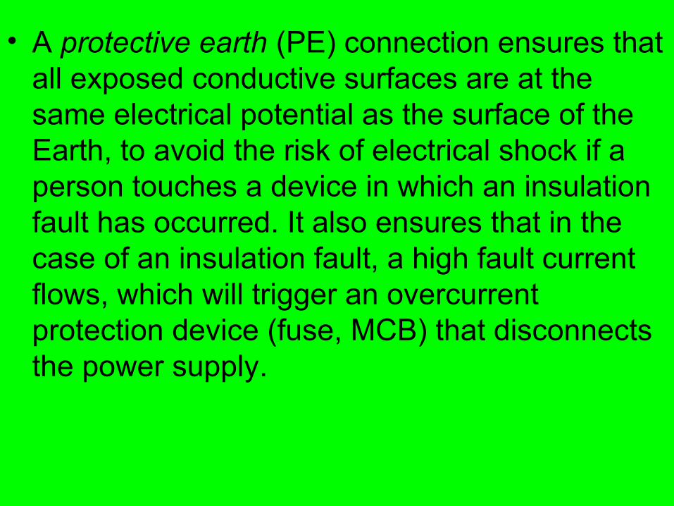
• A protective earth (PE) connection ensures that all exposed conductive surfaces are at the same electrical potential as the surface of the Earth, to avoid the risk of electrical shock if a person touches a device in which an insulation fault has occurred. It also ensures that in the case of an insulation fault, a high fault current flows, which will trigger an overcurrent protection device (fuse, MCB) that disconnects the power supply.
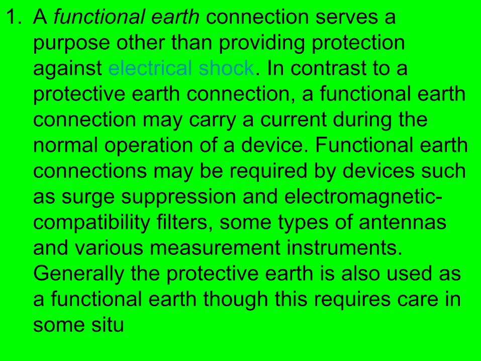
1. A functional earth connection serves a purpose other than providing protection against electrical shock. In contrast to a protective earth connection, a functional earth connection may carry a current during the normal operation of a device. Functional earth connections may be required by devices such as surge suppression and electromagnetic-compatibility filters, some types of antennas and various measurement instruments. Generally the protective earth is also used as a functional earth though this requires care in some situ
IEC nomenclature
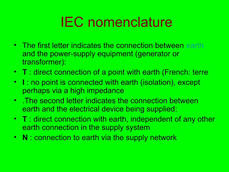
• The first letter indicates the connection between earth and the power-supply equipment (generator or transformer):
• T : direct connection of a point with earth (French: terre• I : no point is connected with earth (isolation), except
perhaps via a high impedance• .The second letter indicates the connection between
earth and the electrical device being supplied:• T : direct connection with earth, independent of any other
earth connection in the supply system• N : connection to earth via the supply network
TN network
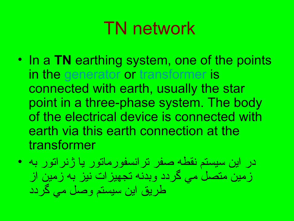
• In a TN earthing system, one of the points in the generator or transformer is connected with earth, usually the star point in a three-phase system. The body of the electrical device is connected with earth via this earth connection at the transformer
• در اين سيستم نقطه صفر ترانسفورماتور يا ژنراتور به زمين متصل مي گردد وبدنه تجهيزات نيز به زمين از طريق اين سيستم وصل مي گردد
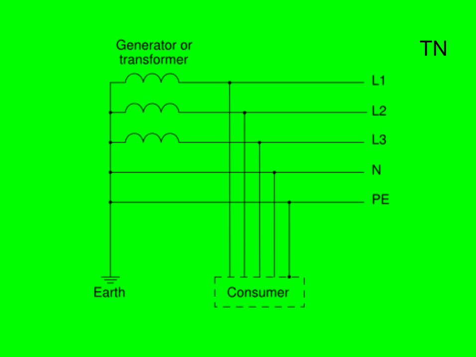
• The conductor that connects the exposed metallic parts of the consumer is called protective earth PE
• . The conductor that connects to the star point in a three-phase system, or that carries the return current in a single-phase system is called neutral N
• . Three variants of TN systems are distinguished:
• TN S‑ : PE and N are separate conductors that are only connected near the power source
• .TN C‑ : A combined PEN conductor fulfills the functions of both a PE and an N conductor
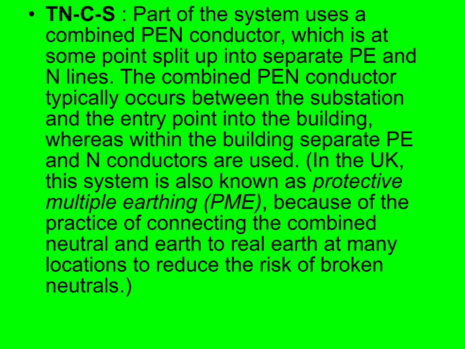
• TN C S‑ ‑ : Part of the system uses a combined PEN conductor, which is at some point split up into separate PE and N lines. The combined PEN conductor typically occurs between the substation and the entry point into the building, whereas within the building separate PE and N conductors are used. (In the UK, this system is also known as protective multiple earthing (PME), because of the practice of connecting the combined neutral and earth to real earth at many locations to reduce the risk of broken neutrals.)
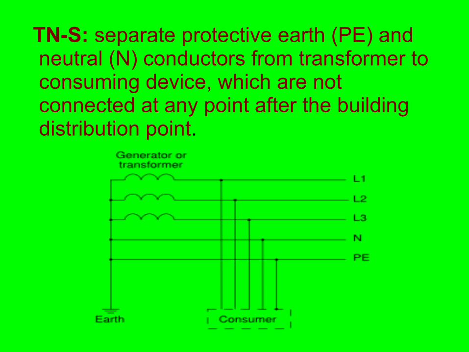
TN-S: separate protective earth (PE) and neutral (N) conductors from transformer to consuming device, which are not connected at any point after the building distribution point.
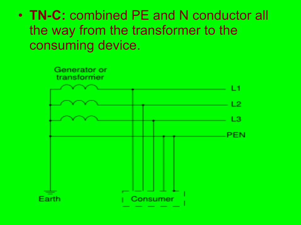
• TN-C: combined PE and N conductor all the way from the transformer to the consuming device.
.

• TN-C-S earthing system: combined PEN conductor from transformer to building distribution point, but separate PE and N conductors in fixed indoor wiring and flexible power cords.
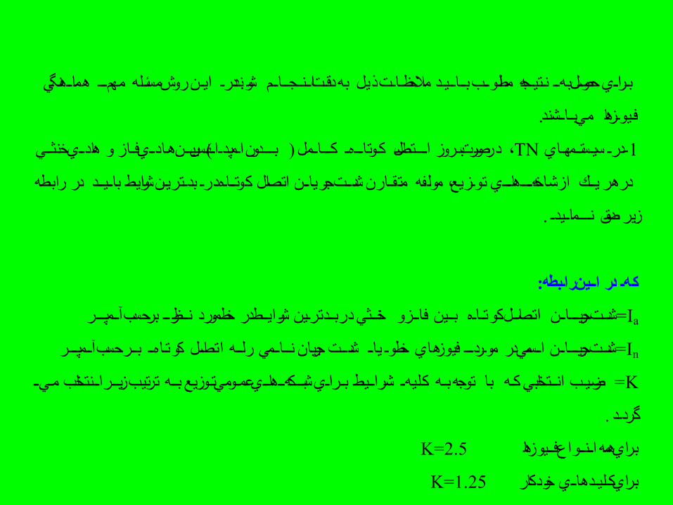
هماااهنگي مهمااا مسئاله روش ايان شوند. درا به دقات اااناجااااام ذيل باااااياد ملظحظااات مطلوااب باراااي ظحصوال بهاا ناتياجه
مي بااااشند. فايوازها
بياان هاادااي فااز و هادااي خنثااي TN-درا سياستاامهااي 1 بااادون اامپدااااناس) ) كاااااامل كاوتااااهاا درصورت باروز اااااتصال ،
كوتااااه اتصال جريااان متقاارن شداات مولفه توازيع، از شاخههااااهااااي در رابطه در هر يااك درا بداتريان شرايط بااايااد
. نااامااايدا صدق زير
كها در اااين راابطه:
Ia= آاامپااار شرايااط در خط مورد نااظراا برظحسب خنااثي در باادتراين فاااز و بااين اتصااال كوتاااه جرياااااان شدات
In= آاامپااار باار ظحسب كوتااهاا جريان نااااامي رلااه اتصااال شداات خط وا يااا مواردااا فيوزهاي جرياااااان اااسمي در شدات
K= زياار ااانتخاب ماياا بااه ترتيب ههااهاااي عماومي تاوزيع شبااك شرااايط بارااي كليهاا توجه باه با انااتخابي كاه ضراياب
. گرداد
K=2.5براي همه ااانااواع فاايوزها
خودكار K=1.25براي كاليادهاااي
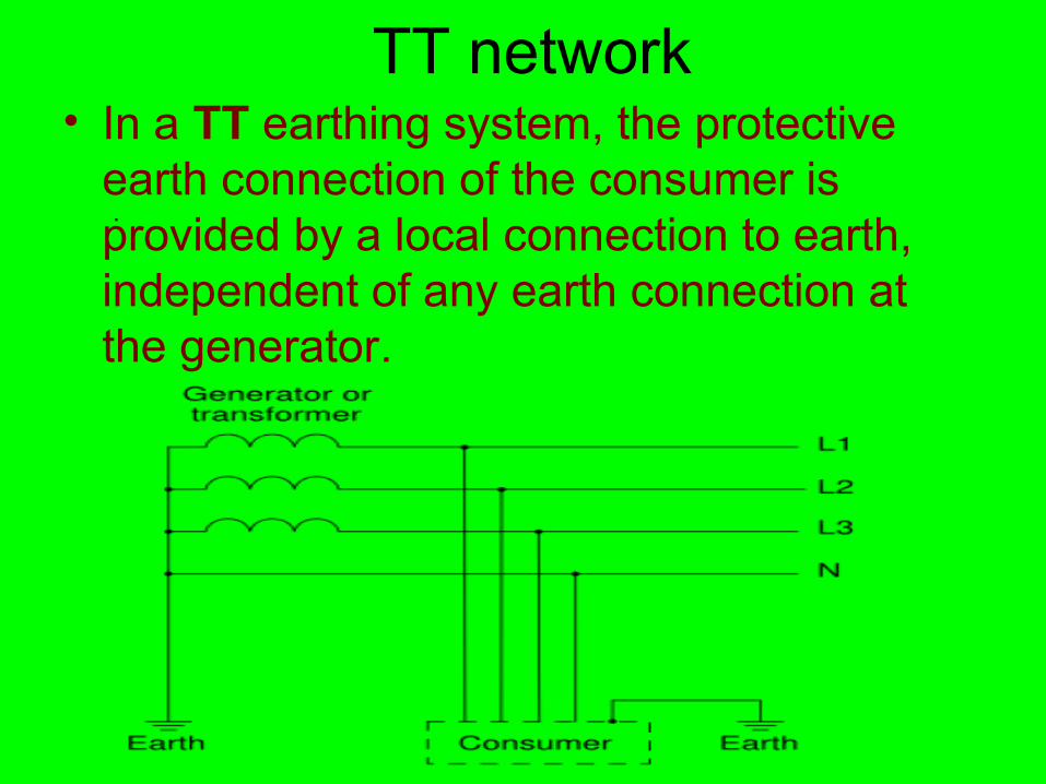
TT network • In a TT earthing system, the protective
earth connection of the consumer is provided by a local connection to earth, independent of any earth connection at the generator.
.
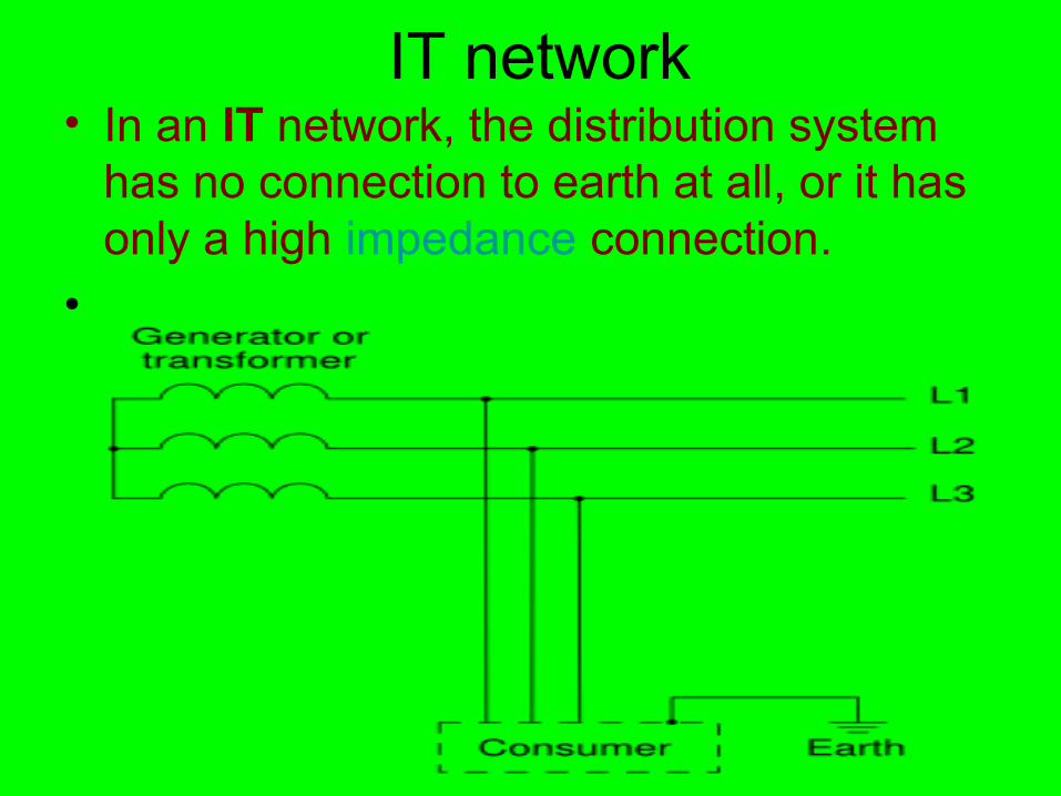
IT network • In an IT network, the distribution system
has no connection to earth at all, or it has only a high impedance connection.
•
: Ο ΗϪϮ
) ΪΟέΩ ΎΘ Ύή ΩΎ ήΑϝϭ ̫ ϟϭϲϧϴϣ ϳ Ϙϣϱ ˰1 .Ωθ Θή ήψ έΩ ΪόΑήΗ ΎΑέΪ Ϯ ϣϪϓ ϧ ϱ Ϙϣϴ ̳ ϻ (ˬ
Θδ γ Ωε έϢϴ ϡˬϭ ϭTT
ΘδγϢ ϴ)ε έ έΩϭ ϦϳTTί Θδ ήΘ ΕΎδγΎΗΎ ΑΎΗΩΎ Ύ ΪΑϱ ϱ (
.Ϊ η λ ί ΑΘδ γ ί Ύμ ΗϧϮϲϣϞ ϭϦϴϣϪϢ ϴϦϴϣϝ
Ύ ΘδγέΩϱ ϫϢϴTTγ ήσί ήΘ Ε ΰ ΠΗ ΩΎ Ύ ΪΑϪϠϭϚϳϖϳ Ϫϛ Ϝϳ Ϝϟ Ϭ ϱ ϫϱ ϫϪϧϪϠϛϴ ϲ ϴ ϴ μΘ ΪΣ ίΩ ήΘ Α ΘχΎΣ ΎΩΎ γ ΑΪΎΑΪη ΖχΎ ΣϞ ϣ ϭϦϴϣϭ ϜϟϚϳϪϲ ϔϱ Ϭϳ ϫϪϠϴϮ ϳ ϧϮϲϣ ϔ
Ϊ ή έή ΩΎΘγΩέ ήγέ σ Α ΘχΎΣ γ Ϊ ΎϦϳˬ ϧϴ̳ ϗϩ ϔ Ϯϣϱ Ϯ Ϫϲ ϔϪϠϴϭ Ϩ̩Ϫ̪ϧ Ϩ̩ .Ϊ ηϧϮΖχΎ Σ γ ήσί ΩΎ Ύ ΪΑί ήή Ωέ έΩΪ ΎΑ ΎϔϪϠϭϚϳϖϳ Ϫϛϱ ϫϱ ϫϪϧ ϩϭ ϫ Ϯϣ ϳ ϥϮϧ ϗϴ ̳
.ΩΩή ΕΎϋή Ω η̳ ϣϮ ϲϣΘδγέΩϢ ϴ ˰TT .ΪηΎΑέ ή ήΑ Θδ ΎΑή ί ς ήηϗ ϲ ϳ ϳ ϳ
: έΩϥ Ϫϛ
ΘχΎΣ ΩΎ ίΩ ήΘ Ζ Ύω Πϲ ϔϱ ϫϭϦϴϣϭ Ϝϟ ϣϭϘϣϮϤϣ :( ΐ δΣήΑϢϫ )
IaΘχΎΣ γ ΗΎΗΩή ϋΐΒγ Ζγ ΎήΟϲ ϔϪϠϴϭϚϴϣϮ ϜϠϤ Ϫϛ ϲϧ ϳ :(ή ΐ δΣήΑ̢ϣ )
.ΩΩή̳ ϲϣΩη ΩΎΘγΪ Ύ ΎΑΎήΟ ΘχΎΣ Ύγί ΎϮ ϣϩ ϔ ϩϧϣ ϗ ϥ ϳ ϔϞϳ ϭ Ϫϛ ϣ Ϩϫˬ ϲ ϲ ϲ ϲ ̴Ia ΎΑΎήΟϲϗ ϥ ϳ
ό ΎΘγΩΩή ϋ ήΑ Ύ Ϊ ΎϲϨϳϩ ̴ ϜϠϤϱ ϲϣϧϩ ϧϣ .ΪηΎΑϲϣΩέ ί ΪηΎΑΎήΟ Ύο ΘχΎΣ γ ΘχΎΣ γ ΘϮϣ Ϝϳ ϥ ϳ Ϫϓ ϔϪϠϭϚϳ ϔϪϠϭϪϛ ϗϭϲ ˬ ϲ ϴ ˬϲ ϴ ϲ
.ΩΩή ήΟΪ ΎΑή ί̳ ϳ ϳ α ό Ύί μΨθ Τ ΎΑ γ ί ΩΎΘγΕέ λέΩϮϜ ϣ ϧϣϪ ϣ Ϩ Ϩϣϱ ϪϠϭ ϩ ϔ Ϯˬ ϲ ϲ ϴ
ΎήΟϥ ϳIaΩ ΪΣέΩ Ωή ϋΚϋΎΑ Ζγ ΎήΟϭ ϥ ϜϠϤ Ϫϛ ϲϧ ϳ 5 .ΩΩή ΎΛ̳ ϲϣϪϴϧ ΎήΟ ϊτ μΨθ Τ ΎΑ γ ί ΩΎΘγΕέ λέΩϥ ϳ ˬϲϧ ϗϪ ϣϲϨ ϨϣϪϠϴϭϚϳ ϩ ϔ Ϯ Ia
. ΩΩή γ ϊ τ ΚϋΎΑ Ζγ ΎήΟ ΪΣ̳ ϲϣϪϠϴϭϥ ϲϧ ϗ Ϫϛ ϲϧ ϳ ϞϗΑ ΎμΗϪϝ ) ί Ύγ δ ΎΘ ί Ϊ ΎΑΪηΎΒήΟ ΑΎ ς ήη ΎϲϜϤϛ Ϟϴ ϧ̡ Ϣϫ ϳ ϧ Ϟ ϗϕϮϓ ϳ Ϫ̪ϧϨ̩
.Ωή ΩΎΘγϛϩ ϔ ( ΑΎΗ Α Ωΰ Ϊη ί ΰ Ύ ί ΎγϮϠ ϪϚϳ ϧϩ Ϧ ϣϱ Ϡϓϱ ϫϩϴ
ί ΘδγΙ ΪΣ ΤϦϴϣϢ ϴ ϩϮ ϧ
ΩέΩΩΟ ΘΨ Ύη έ ί ΎμΗ ΎΖ Ύ Α Ϊγέ ήΑϪϛ Ϯ ϭ ϔϠϣϱ Ϭϭ Ϧ ϣϝ Ϧ ϣ ϭ ϘϣϚϳϪϥ ϱϲ ˬ ϴ ϴ ̡ ϴ
Ι ΪΣ Ύη έ ήΗΞέίϱ Ϭ ϭ Ϧϳ ϳ ϲϜϳ .ΖγΪηΡήτ Ύγέ Ύηέΰ έΩϩ ϣϲϟ ϱ Ϭ ̳
ΎΑ Ω ΩΎΠ ΎΑ ί Ύ έ τΑϝ Ϯ̳ Ϛϳ ϳ Ϧϴϣϩ ̩ ϲϠϛϮ .Ζγ « ί ΎϦϴϣϩ ̩ » Ύ ί Θδγϥ ϤϫˬϦϴϣϢ ϴ
έή Ω ήΘ ϋέΩ Ω η Θή ήψ έΩή Θήτ ϋϗϭ ϜϟϚϳϥ ϖϤ Ϫϛ Ϯ ϲϣϪϓ̳ ϧ ϴϐϣ ϗϭϖϤ
έή Ύ ΗέΩϗϩ ̩ Ϫ ( δ Τ λϲ ϣϪ ϔ )Ω ήΘ ί ΎΙΪΣ ήΑϭ ϜϟϚϳ ˬϦϴϣϩ ̩ ϱ .Ωήϴ̳ϲϣ
Ζ ΎΨο Α ΪΣ ήσέΩ Θήϣ ϪϞϗ ˬϥϑ ϭϪϓ̳20ΎΫέΩ ήσή ίήΘ ΘΎγϝ Ϗ Ϯ̡ϑ ϫ Ϥϴϧ
ΎΑΎΘβ γϭϨϣ ̢ .Ωη Ϊ Α ΘΨέ ΰϮ ϣϩ ϮϛϭϪ ϳ ϡ ϫϲ ϴ ϴ5ΪηΪ ήγ ΩήΧ γϭϩ ϧ ϭ ϚϤϧ̲ Ϩ Ϫϳϻ5
Ζ ΎΨο Α ή ΎΫέΩϣ ϪϚϳ ϫˬ ϝ Ϗ Ϯ̡Ϫϳϻ15ΎϪϜϨϳϳϭ ) ΘΨέ Ύ ΧΩέΩήΘΘΎγϪ ϳ ϩ Ϟ Ϥ ϧ̩ ϴ
ΖΒδ Αέ ΎΧϧϪ ϙ / ΎΫϝ Ϗ / ρ ΨϚϤϧ ϮϠϣ1/5/0/10ωΎΗέΎΗ Ω ΩΎΠϔ ϭϩϮϤϧ ϳ 5/1
Properties • TN networks save the cost of a low-impedance
earth connection at the site of each consumer. Such a connection (a buried metal structure) is required to provide protective earth in IT and TT systems.
• TN-C networks save the cost of an additional conductor needed for separate N and PE connections. However to mitigate the risk of broken neutrals, special cable types and lots of connections to earth are needed.
• TT networks require RCD protection and often an expensive time delay type is needed to provide discrimination with an RCD downstream
Safety
• In TN an insulation fault is very likely to lead to a high short-circuit current that will trigger an overcurrent circuit-breaker or fuse and disconnect the L conductors.
• In the majority of TT systems the earth fault loop impedance will be too high to do this and so an RCD must be employed
• In TN-S and TT systems (and in TN-C-S beyond the point of the split), a residual-current device can be used as an additional protection. In the absence of any insulation fault in the consumer device, the equation IL1+IL2+IL3+IN = 0 holds, and an RCD can disconnect the supply as soon as this sum reaches a threshold (typically 10-500 mA). An insulation fault between either L or N and PE will trigger an RCD with high probability
• In IT and TN-C networks, residual current devices are far less likely to detect an insulation fault.
• In a TN-C system they would also be very vulnerable to unwanted triggering from contact between earths of circuits on different RCDs or with real ground thus making their use impractical. Also RCDs usually isolate the neutral core which is dangerous in a TN-C system.
• In single-ended single-phase systems where the Earth and neutral are combined (TN-C and the part of TN-C-S systems which uses a combined neutral and earth core) if there is a contact problem in the PEN conductor, then all parts of the earthing system beyond the break will raise to the potential of the L conductor. In an unbalanced multi phase system the potential of the earthing system will move towards that of the most loaded live conductor. Therefore, TN-C connections must not go across plug/socket connections or flexible cables, where there is a higher probability of contact problems than with fixed wiring. There is also a risk if a cable is damaged which can be mitigated by the use of concentric cable construction and/or multiple earth electrodes. Due to the (small) risks of the lost neutral, use of TN-C-S supplies is banned for caravans and boats in the UK and it is often recommended to make outdoor wiring TT with a separate earth electrode
• In IT systems, a single insulation fault is unlikely to cause dangerous currents to flow through a human body in contact with earth, because no low-impedance circuit exists for such a current to flow. However, a first insulation fault can effectively turn an IT system into a TN system, and then a second insulation fault can lead to dangerous body currents. Worse, in a multi-phase system if one of the lives made contact with earth it would cause the other phase cores to rise to the phase-phase voltage relative to earth rather than the phase-neutral voltage. IT systems also experience larger transient overvoltages than other systems
• In TN-C and TN-C-S systems any connection between the combined neutral and earth core and the body of the earth could end up carrying significant current under normal conditions and could carry even more under a broken neutral situation.
• Therefore main equipotential bonding conductors must be sized with this in mind and use of TN-C-S is inadvisable in situations like petrol stations where there is a combination of lots of buried metalwork and explosive gases.
• In TN-C and TN-C-S systems any break in the combined neutral and earth core which didn't also affect the live conductor could theoretically result in exposed metalwork rising to near "live" potential
Electromagnetic compatibility • In TN-S and TT systems, the consumer has a
low-noise connection to earth, which does not suffer from the voltage that appears on the N conductor as a result of the return currents and the impedance of that conductor. This is of particular importance with some types of telecommunication and measurement equipment.
• In TT systems, each consumer has its own high-quality connection with earth, and will not notice any currents that may be caused by other consumers on a shared PE line.
Regulations • In most residential installations in the U. S. and Canada,
the feed from the distribution transformer uses a combined neutral and grounding conductor (two phase and one neutral, for three wires total), but within the residence separated neutral and protective earth conductors are used (TN-C-S). The neutral must only be connected to earth ground on the supply side of the customer's disconnecting switch. Additional connections of neutral to ground within the customer's wiring are prohibited.
• For wiring less than 1000 V, the United States National Electrical Code and Canadian electrical code forbid the use of systems that combine the grounding conductor and neutral beyond the customer's disconnecting switch.
• In Argentina and France the customer must provide its own ground connection (TT).
Application examples • Most modern homes in Europe have a TN-C-S
earthing system. The combined neutral and earth occurs between the nearest transformer substation and the service cut out (the fuse before the meter). After this separate earth and neutral cores are used in all the internal wiring.
• Older urban and suburban homes in the UK tend to have TN-S supplies with the earth delivered through the lead sheath of the underground lead and paper cable.
• Some older homes, especially those built before the invention of residual-current circuit breakers and wired home area networks, use an in-house TN-C arrangement. This is no longer recommended practice
• Laboratory rooms, medical facilities, construction sites, repair workshops, and other environments where there is an increased risk of insulation faults often use an IT earthing arrangement supplied from an isolation transformer. To mitigate the two fault issues with IT systems the isolation transformers should only supply a small number of loads each and/or should be protected with special monitoring gear (generally only medical IT systems are done with such gear because of the cost).
• In remote areas, where the cost of an additional PE conductor outweighs the cost of a local earth connection, TT networks are commonly used in some countries especially in older properties.
• TT supplies to individual properties are also seen in mostly TN-C-S systems where an individual property is considered unsuitable for TN-C-S supply. (e.g. petrol stations).