16qam symbol timing recovery in the upstream transmission of docsis standard
TRANSCRIPT
IEEE TRANSACTIONS ON BROADCASTING, VOL. 49, NO. 2, JUNE 2003 211
16QAM Symbol Timing Recovery in the UpstreamTransmission of DOCSIS Standard
Jianxin Wang and Joachim Speidel
Abstract—This paper investigates the performance of the digitalsymbol timing recovery schemes for 16QAM upstream transmis-sion of DOCSIS Standard. Two forms of nonlinearity are consid-ered: the magnitude square operation and the delay multiplicationoperation, both of which generate the output signal that containsthe symbol timing information. The detailed analysis for the mag-nitude square timing recovery is given in digital domain, and con-sequently the symbol timing estimate can be directly obtained bydiscrete Fourier transform. The simulation results show that themagnitude square timing recovery and delay multiplication timingrecovery algorithms suffer from the same problem that the esti-mation error is reduced slowly at high signal-to-noise ratios due tothe effect of self-noise. To this end, the third scheme, which is themagnitude square timing recovery with prefilter, is examined. Thisscheme shows a superior performance and a comparison with theresults of the other two schemes is made.
Index Terms—Bit synchronization, digital demodulation,DOCSIS, symbol timing, upstream transmission.
I. INTRODUCTION
T HE DOCSIS (data over cable service interface specifi-cation) documents describe the network interface for a
system that allows bidirectional transfer of IP traffic over HFC(hybrid fiber-coax) networks. The upstream transmission (fromthe cable modem or set-top-box to the headend) modulationformat can be QPSK or 16QAM [1], [2]. DOCSIS 2.0 also sup-ports 8, 32 and 64 QAM. The digital realization of the receiverat the headend is of growing interest with the availability ofhigh speed DSP (digital signal processor). The symbol timingrecovery or bit synchronization is essential to any demodula-tion for QPSK or QAM.
A digital nondecision-aided timing recovery algorithmfor QPSK is presented in [3] where only two samples persymbol are employed. But the pattern noise is introduced ifthis algorithm is extended to the QAM timing recovery. Someimproved algorithms were proposed to mitigate the problem[4]–[6]. These solutions, however, only generate the timingerror signal used to control the clock phase of A/D converter.Because of the advantages of DSP implementation, we havethe target to run the A/D converter at a fixed clock frequencyand all further processing should be done digitally. Thus, no
Manuscript received March 22, 2001; revised March 20, 2003.J. Wang was with the Institute of Telecommunications, University of
Stuttgart and is now with the Department of Electronic Engineering, NanjingUniversity of Science and Technology, 210094 Nanjing, P. R. China (e-mail:[email protected]; [email protected]).
J. Speidel is with the Institute of Telecommunications, Universityof Stuttgart, Pfaffenwaldring 47, 70569 Stuttgart, Germany (e-mail:[email protected]).
Digital Object Identifier 10.1109/TBC.2003.813647
feedback of signals to the sampling clock generator is required[7]–[10]. In [7] and [8] the input signal is oversampled andthe symbol timing estimation is performed by choosing fromthe possible sampling points the one that corresponds to themaximum average opening of the eye-pattern. The timingaccuracy depends on the oversampling rate or the number ofthe samples per symbol. In some situations, however, we wouldlike to decrease the number of the samples per symbol as muchas possible in order to save the computational complexity orimplementation complexity. The methods for this purpose arecomposed of passing the incoming signal through a nonlineardevice [11], [12] and then directly estimating the symbol timing[10], which are investigated in this paper for the symbol timingrecovery in the upstream transmission of DOCSIS Standard.Two forms of nonlinearity are considered: the magnitudesquare operation and the delay multiplication operation. Thedetailed analysis for the magnitude square timing recovery isgiven in digital domain. The magnitude square timing recoverywith prefilter is examined, to combat the self-noise caused bythe square law rectifier [13].
This paper is organized as follows: The magnitude squaretiming recovery algorithm is described in Section II, and the de-tailed analysis is made in the digital domain. Section III givesthe result of the delay multiplication timing recovery. The ap-proach to mitigating the self-noise is discussed in Section IV,and a comparison is made for the three timing recovery algo-rithms. Finally, conclusions are provided in Section V.
II. THE MAGNITUDE SQUARE TIMING RECOVERY
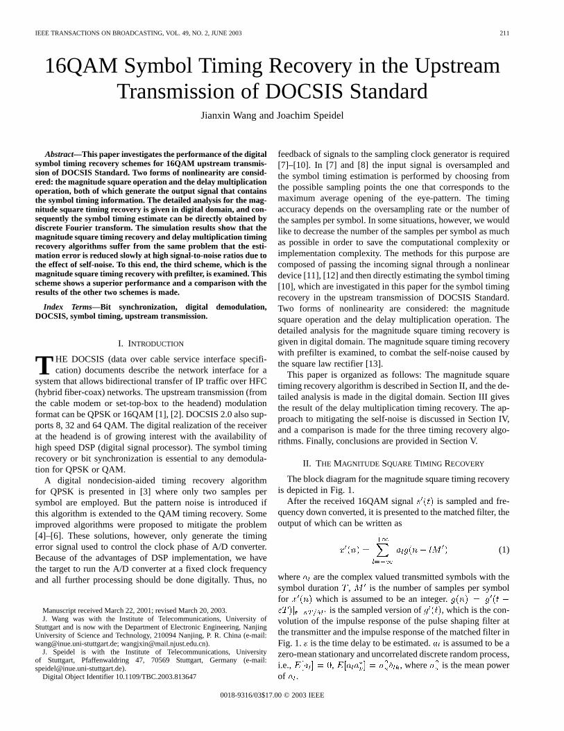
The block diagram for the magnitude square timing recoveryis depicted in Fig. 1.
After the received 16QAM signal is sampled and fre-quency down converted, it is presented to the matched filter, theoutput of which can be written as
(1)
where are the complex valued transmitted symbols with thesymbol duration , is the number of samples per symbolfor which is assumed to be an integer.
is the sampled version of , which is the con-volution of the impulse response of the pulse shaping filter atthe transmitter and the impulse response of the matched filter inFig. 1. is the time delay to be estimated.is assumed to be azero-mean stationary and uncorrelated discrete random process,i.e., , , where is the mean powerof .
0018-9316/03$17.00 © 2003 IEEE
212 IEEE TRANSACTIONS ON BROADCASTING, VOL. 49, NO. 2, JUNE 2003
Fig. 1. Block diagram of the magnitude square timing recovery.
The filtered output sequence is decimated by a factorof , generating
(2)
Let denote the number of samples per symbol forwhich is assumed to be an integer, i.e., , and thenthe sampling rate of is .
Squaring (2) produces
(3)
Equation (3) can be expressed as the sum of a mean value anda self-noise term [12], i.e.,
(4)
where
(5)
(6)
is a zero-mean cyclostationary self-noise.is the mean value with period , and thus contains
the desired frequency component at (or in the analogdomain). can be represented in the form of discrete Fourierseries
(7)
where
for even (8)
and because of the real
for (9)
Substituting (5) into (8), we obtain
for (10)
where is the Fouriertransform of and is the normalizedfrequency.
If the sampling rate for is such that theNyquist sampling theorem is satisfied for sampling of ,we have
for (11)
where is the Fourier transform of , and.
According to the convolution property of Fourier transform,can be written as
(12)
where is the Fourier transform of , and is a raisedcosine function.
By using (10)–(12), is given as follows
for (13)
Due to the bandwidth limitation for , only two termswith in (13) are nonzero. Evaluating the integral of(13) for the raised cosine function with roll-off andmagnitude 1, yields
(14)
(15)
According to (9), we have
(16)
Thus, (7) can be written as the sum of a dc component and asinusoidal signal
(17)
WANG AND SPEIDEL: 16QAM SYMBOL TIMING RECOVERY 213
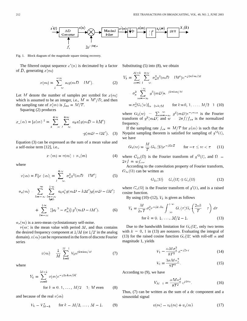
Fig. 2. The spectrum of the output signalx (m) of the magnitude squareoperation.
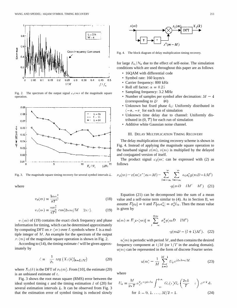
Fig. 3. The magnitude square timing recovery for several symbol intervalsL.
where
(18)
(19)
of (19) contains the exact clock frequency and phaseinformation for timing, which can be determined approximatelyby computing DFT on over symbols where is a mul-tiple integer of . An example for the spectrum of the output
of the magnitude square operation is shown in Fig. 2.According to (14), the timing estimatewill be given approx-
imately by
(20)
where is the DFT of . From [10], the estimate (20)is an unbiased estimate of.
Fig. 3 shows the root mean square (RMS) error between theideal symbol timing and the timing estimation of (20) forseveral estimation intervals. It can be observed from Fig. 3that the estimation error of symbol timing is reduced slowly
Fig. 4. The block diagram of delay multiplication timing recovery.
for large due to the effect of self-noise. The simulationconditions which are used throughout this paper are as follows
• 16QAM with differential code• Symbol rate: 160 ksym/s• Carrier frequency: 800 kHz• Roll off factor:• Sampling frequency: 3.2 MHz• Number of samples per symbol after decimation:
(corresponding to )• Unknown but fixed phase : Uniformly distributed in
for each run of simulation• Unknown time delay due to channel: Uniformly dis-
tributed in (0, ] for each run of simulation• Additive white Gaussian noise channel.
III. D ELAY MULTIPLICATION TIMING RECOVERY
The delay multiplication timing recovery scheme is shown inFig. 4. Instead of applying the magnitude square operation tothe baseband signal , is multiplied by the delayedand conjugated version of itself.
The product signal can be expressed with (2) asfollows
(21)
Equation (21) can be decomposed into the sum of a meanvalue and a self-noise term similar to (4). As in Section II, weassume and . Then the mean valueis given by
(22)
is periodic with period , and then contains the desiredfrequency component at (or in the analog domain).
can be represented in the form of discrete Fourier series
(23)
where
for (24)
214 IEEE TRANSACTIONS ON BROADCASTING, VOL. 49, NO. 2, JUNE 2003
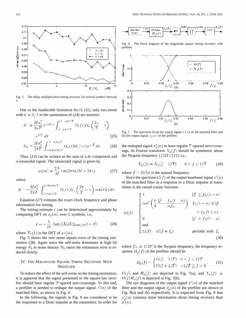
Fig. 5. The delay multiplication timing recovery for several symbol intervalsL.
Due to the bandwidth limitation for , only two termswith in the summation of (24) are nonzero
(25)
(26)
Thus, (23) can be written as the sum of a dc component anda sinusoidal signal. The sinusoidal signal is given by
(27)
where
Equation (27) contains the exact clock frequency and phaseinformation for timing.
The timing estimate can be determined approximately bycomputing DFT on over symbols, i.e.,
(28)
where is the DFT of .Fig. 5 shows the root mean square error of the timing esti-
mation (28). Again since the self-noise dominates at high bitenergy to noise density ratios the estimation error is re-duced slowly.
IV. THE MAGNITUDE SQUARE TIMING RECOVERY WITH
PREFILTER
To reduce the effect of the self-noise on the timing estimation,it is apparent that the signal presented to the square-law recti-fier should have regular -spaced zero-crossings. To this end,a prefilter is needed to reshape the output signal of thematched filter, as shown in Fig. 6.
In the following, the signals in Fig. 6 are considered to bethe responses to a Dirac impulse at the transmitter. In order for
Fig. 6. The block diagram of the magnitude square timing recovery withprefilter.
Fig. 7. The spectrum of (a) the output signalx (n) of the matched filter and(b) the output signalx (n) of the prefilter.
the reshaped signal to have regular -spaced zero-cross-ings, its Fourier transform should be symmetric aboutthe Nyquist frequency [11], i.e.,
(29)
where is the natural frequency.Since the spectrum of the output baseband signal
of the matched filter as a response to a Dirac impulse at trans-mitter is the raised cosine function,
and
periodic with
(30)
where is the Nyquist frequency, the frequency re-sponse of the prefilter should be
(31)
and are depicted in Fig. 7(a), andis depicted in Fig. 7(b).
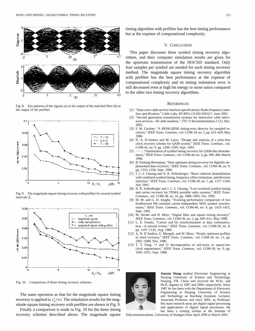
The eye diagrams of the output signal of the matchedfilter and the output signal of the prefilter are shown inFig. 8(a) and (b) respectively. It is expected from Fig. 8 that
contains more information about timing recovery than.
WANG AND SPEIDEL: 16QAM SYMBOL TIMING RECOVERY 215
Fig. 8. Eye patterns of the signals (a) at the output of the matched filter (b) atthe output of the prefilter.
Fig. 9. The magnitude square timing recovery with prefilter for several symbolintervalsL.
Fig. 10. Comparison of three timing recovery schemes.
The same operation as that for the magnitude square timingrecovery is applied to . The simulation results for the mag-nitude square timing recovery with prefilter are shown in Fig. 9.
Finally a comparison is made in Fig. 10 for the three timingrecovery schemes described above. The magnitude square
timing algorithm with prefilter has the best timing performancebut at the expense of computational complexity.
V. CONCLUSION
This paper discusses three symbol timing recovery algo-rithms, and their computer simulation results are given forthe upstream transmission of the DOCSIS standard. Onlyfour samples per symbol are needed for each timing recoverymethod. The magnitude square timing recovery algorithmwith prefilter has the best performance at the expense ofcomputational complexity and its timing estimation error isstill decreased even at high bit energy to noise ratios comparedto the other two timing recovery algorithms.
REFERENCES
[1] “Data-over-cable service interface specifications; Radio frequency inter-face specification,” Cable Labs, SP-RFIv.2.0-I02-020 617, June 2002.
[2] “Second generation transmission systems for interactive cable televi-sion services—IP cable modems,”, ITU-T Recommendation J.122, Dec.2002.
[3] F. M. Gardner, “A BPSK/QPSK timing-error detector for sampled re-ceivers,”IEEE Trans. Commun., vol. COM-34, no. 5, pp. 423–429, May1986.
[4] N. A. D’Andrea and M. Luise, “Design and analysis of a jitter-freeclock recovery scheme for QAM system,”IEEE Trans. Commun., vol.COM-41, no. 9, pp. 1296–1299, Sept. 1993.
[5] , “Optimization of symbol timing recovery for QAM data demodu-lators,”IEEE Trans. Commun., vol. COM-44, no. 3, pp. 399–406, March1996.
[6] B. Farhang-Boroujeny, “Near optimum timing recovery for digitally im-plemented data receivers,”IEEE Trans. Commun., vol. COM-38, no. 9,pp. 1333–1336, Sept. 1990.
[7] J. C.-I. Chuang and N. R. Sollenberger, “Burst coherent demodulationwith combined symbol timing, frequency offset estimation, and diversityselection,”IEEE Trans. Commun., vol. COM-39, no. 7, pp. 1157–1164,July 1991.
[8] N. R. Sollenberger and J. C.-I. Chuang, “Low-overhead symbol timingand carrier recovery for TDMA portable radio systems,”IEEE Trans.Commun., vol. COM-38, no. 10, pp. 1886–1892, Oct. 1990.
[9] M. M. and G. D. Jonghe, “Tracking performance comparison of twofeedforward ML-oriented carrier-independent NDA symbol synchro-nizers,” IEEE Trans. Commun., vol. COM-40, no. 9, pp. 1423–1425,Sept. 1992.
[10] M. Oerder and H. Meyr, “Digital filter and square timing recovery,”IEEE Trans. Commun., vol. COM-36, no. 5, pp. 605–611, May 1988.
[11] L. E. Franks, “Carrier and bit synchronization in data communica-tion—A tutorial review,” IEEE Trans. Commun., vol. COM-28, no. 8,pp. 1107–1120, Aug. 1980.
[12] A. N. D’Andrea, U. Mengali, and M. Moro, “Nearly optimum prefilterin clock recovery,”IEEE Trans. Commun., vol. COM-34, no. 11, pp.1081–1088, Nov. 1986.
[13] T. T. Fang, “I and Q decomposition of self-noise in square-lawclock regenerators,”IEEE Trans. Commun., vol. COM-36, no. 9, pp.1045–1051, Sept. 1988.
Jianxin Wang studied Electronic Engineering atNanjing University of Science and Technology,Nanjing, P.R. China and received the M.Sc. andPh.D. degrees in 1987 and 2000, respectively. Since1987 he has been with the Department of ElectronicEngineering at Nanjing University of Scienceand Technology as Teaching Assistant, Lecturer,Associate Professor and since 2001, as Professor.His main research areas are digital signal processingand applications of digital signal processors. Hehas been a visiting scholar at the Institute of
Telecommunications, University of Stuttgart from April 2000 to March 2001.
216 IEEE TRANSACTIONS ON BROADCASTING, VOL. 49, NO. 2, JUNE 2003
Joachim Speidel studied Electrical Engineeringand Information Technology at the University ofStuttgart, Germany, and received his Dipl.-Ing. andDr.-Ing. degrees in 1975 and 1980, respectively,all summa cum laude. From 1980 to 1992 heworked for Philips Communications (today LucentTechnologies Bell Labs Innovations, Germany) inthe field of digital communications, ISDN and videocommunications. During his industry career he hasheld various positions in R&D, as a member oftechnical staff, laboratory head and finally as Vice
President. Since autumn 1992 he has been Full Professor at the Universityof Stuttgart and Head of the Institute of Telecommunications. His researchareas are digital multimedia communications in mobile, optical and electricalnetworks with emphasis on modulation, source and channel coding.