14-specific system cellular-part-2 - ku ittc · – length of preamble = 128 chips ... • both...
TRANSCRIPT
#14 1
Victor S. FrostDan F. Servey Distinguished Professor
Electrical Engineering and Computer ScienceUniversity of Kansas2335 Irving Hill Dr.
Lawrence, Kansas 66045Phone: (785) 864-4833 FAX:(785) 864-7789
e-mail: [email protected]://www.ittc.ku.edu/
Specific Systems:
Cellular#14
Part 2: EV-DO
All material copyright 2006Victor S. Frost, All Rights Reserved
#14 2
Outline
• Part 1– Basic components– 3G – Overview of W-CDMA/UMTS– HSPDA
• Part 2– EV-DO overview (Slides provided by Soshant
Bali, Ph.D. EE, University of Kansas, 2007)– Case study: Mitigating scheduler-induced
starvation in 3G wireless networks
Slides provided by Soshant Bali, Ph.D, University of Kansas, 2007
#14 3
EV-DO overview-Outline• Introduction• Network Architecture• Simplified Protocol Stack• Air Interface Protocol Layers• Forward Link
– MAC Layer – PHY Layer
• Reverse Link– MAC Layer– PHY Layer
• Some Interesting Features– Radio Link Protocol– Adaptive modulation and coding– Hybrid ARQ
#14 4
Introduction• 1xEV-DO: 1x Evolution for Data Optimized
– 3G data rates: up to 2.45Mbps downlink, 153.6Kbps uplink– Natural evolution from IS-95, IS-2000– Evolution: leverage existing network elements– Optimized for data transfer
• IS-2000 needs 3.75MHz spectrum for 2.07 Mbps• EV-DO only 1.25MHz spectrum for 2.45 Mbps
• Data service characteristics– Rates asymmetric
• EV-DO: higher rate in forward link – Latency can be tolerated
• EV-DO: uses link layer ARQ• EV-DO: powerful error-correcting codes (e.g., turbo codes)
– Transmissions are in burst• EV-DO: uses time-division multiplexing
#14 5
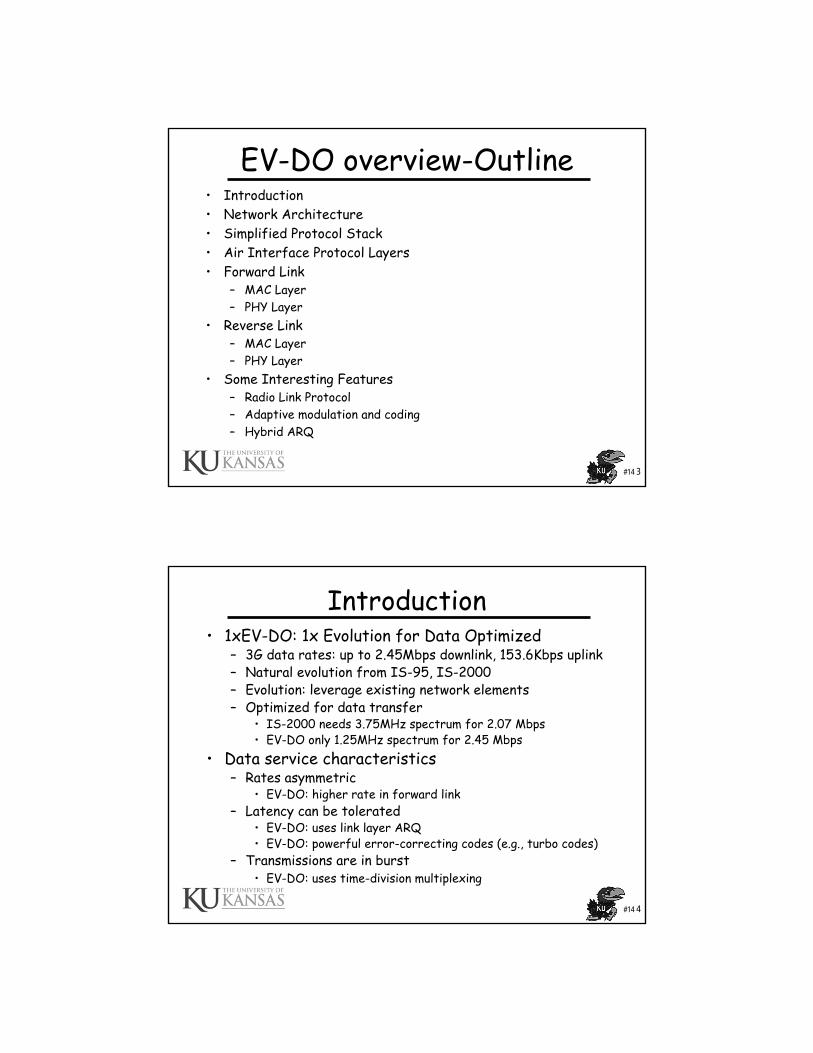
EV-DO network architecture
AT
AT
AT = Access Terminal
BTS
BTS
BTS
Router RNC
PCF PDSNInternet
AN: Access Network1 per major area, e.g. city
Although Router shown above is nota part of the standard, typical implementationsof EV-DO use Juniper or Cisco routers as aggregation router.
~50 BTS per AN
PCF = Packet Control Function
#14 6
Network architecture• Base Transceiver Station (BTS)
– RF components for transmitting/receiving signals– Software/hardware for digital communications/DSP– Connected to RNC with backhaul links
• Radio Network Controller (RNC)– Session establishment and release– Frame selection– Radio Link Protocol (RLP) processing
• Access Network (AN)– BTS and RNC form the AN
• Packet Control Function (PCF)– Allows RNC functions to interface with PDSN
• Packet Data Service Node (PDSN)– Interfaces with Internet– Home/Foreign agent for mobile IP– Terminates PPP connection with AT
#14 7
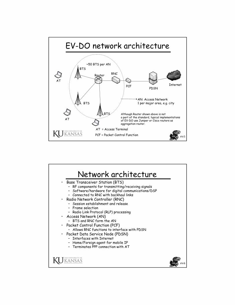
Simplified protocol stack
AT BTS RNC/PCF PDSN Internet Server
TCP/UDP
TCP/UDP
IP IP IP
L2
L1
L2
L1
PPP PPP
RLP RLP GREGRE
IP IP
L2/L1
L2/L1
MACMAC
PHY PHY
GRE= Generic Routing Encapsulation
#14 8
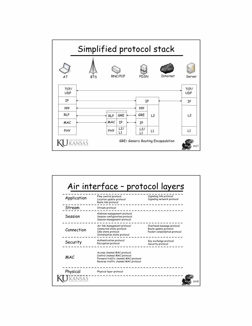
Air interface – protocol layers Application
Stream
Session
Connection
Security
MAC
Physical
Flow control protocolLocation update protocolRadio link protocol
Signaling link protocolSignaling network protocol
Stream protocol
Address management protocolSession configuration protocolSession management protocol
Air link management protocolConnected state protocolIdle state protocolInitialization state protocol
Overhead message protocolRoute update protocolPacket consolidation protocol
Authentication protocolEncryption protocol
Key exchange protocolSecurity protocol
Access channel MAC protocolControl channel MAC protocolForward traffic channel MAC protocolReverse traffic channel MAC protocol
Physical layer protocol
#14 9
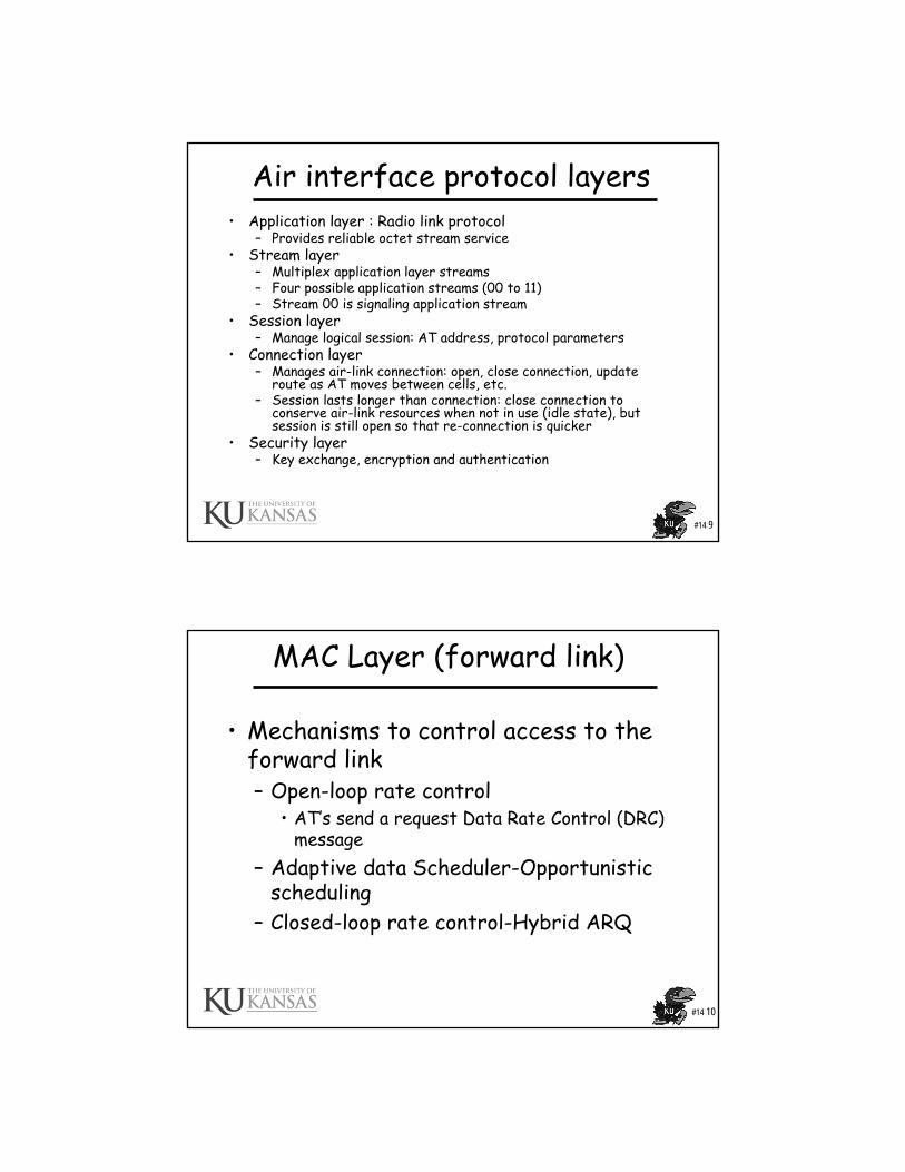
Air interface protocol layers• Application layer : Radio link protocol
– Provides reliable octet stream service• Stream layer
– Multiplex application layer streams– Four possible application streams (00 to 11)– Stream 00 is signaling application stream
• Session layer– Manage logical session: AT address, protocol parameters
• Connection layer– Manages air-link connection: open, close connection, update
route as AT moves between cells, etc.– Session lasts longer than connection: close connection to
conserve air-link resources when not in use (idle state), but session is still open so that re-connection is quicker
• Security layer– Key exchange, encryption and authentication
#14 10
MAC Layer (forward link)
• Mechanisms to control access to the forward link– Open-loop rate control
• AT’s send a request Data Rate Control (DRC) message
– Adaptive data Scheduler-Opportunistic scheduling
– Closed-loop rate control-Hybrid ARQ
#14 11
MAC Layer (forward link)• Forward traffic channel MAC
– TDM on the downlink– Control rate of transmission
• Each AT measures SINR• Reports to AN on data rate control (DRC) channel• AN sends at the requested rate• AN chooses appropriate modulation/coding for SINR
• Control channel MAC – Generates control channel MAC packets– Sent on shared control channel– ATs identified using AT identifier record in header– All ATs read identifier– If packet destined to that AT then read rest of packet
#14 12
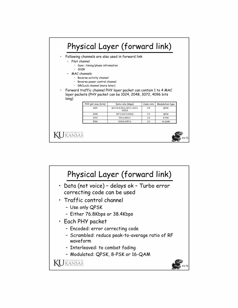
Downlink Slot Structure
Modified From: Naga Bhushan, Chris Lott, Peter Black, Rashid Attar, Yu-Cheun Jou, Mingxi Fan, Donna Ghosh, andJean Au, “CDMA2000 1xEV-DO Revision A: A Physical Layer and MAC Layer Overview,”IEEE Communications Magazine, February 2006
1.666ms
#14 13
Physical Layer (forward link)• Following channels are also used in forward link
– Pilot channel • Sync- timing/phase infromation• SNIR
– MAC channels• Reverse activity channel• Reverse power control channel• DRCLock channel (more later)
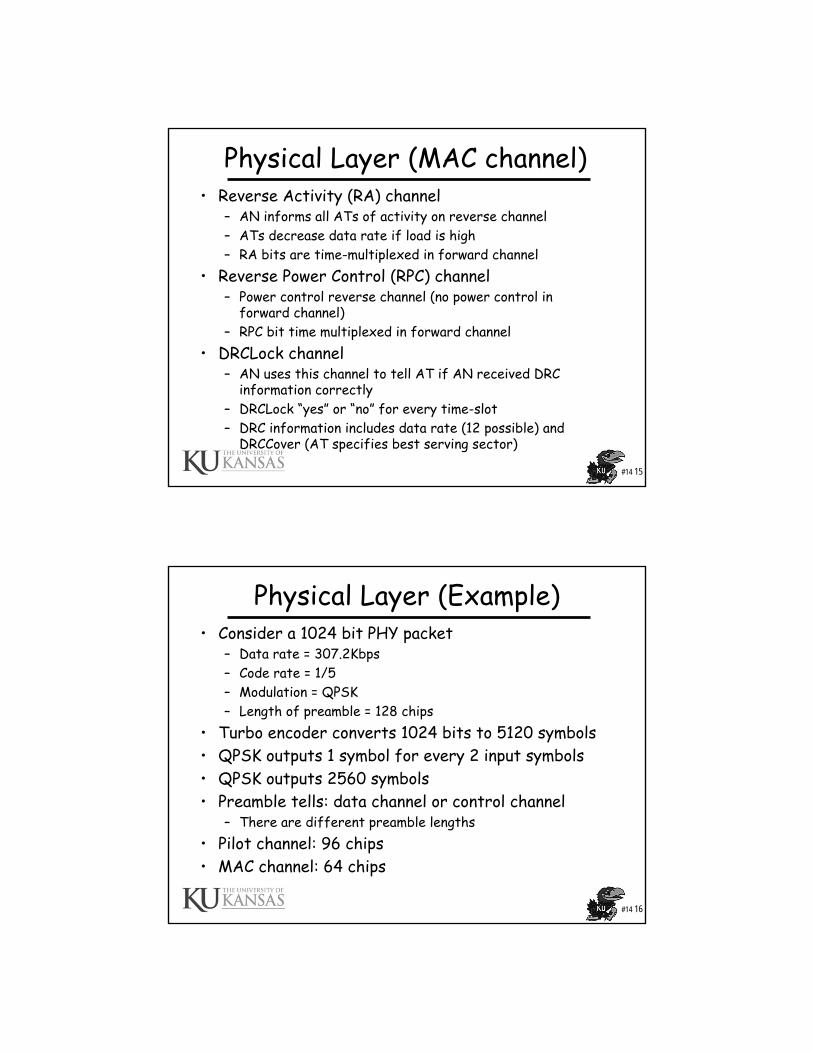
• Forward traffic channel PHY layer packet can contain 1 to 4 MAC layer packets (PHY packet can be 1024, 2048, 3072, 4096 bits long)
16-QAM1/31228.8,2457.64096
8-PSK1/3912.6,1843.23072
QPSK1/3307.2,614.4,1228.82048
QPSK1/538.4,76.8,153.6,307.2, 614.4, 1228.8
1024
Modulation typeCode rateData rate (kbps)PHY pkt size (bits)
#14 14
Physical Layer (forward link)• Data (not voice) – delays ok – Turbo error
correcting code can be used• Traffic control channel
– Use only QPSK– Either 76.8Kbps or 38.4Kbps
• Each PHY packet– Encoded: error correcting code– Scrambled: reduce peak-to-average ratio of RF
waveform– Interleaved: to combat fading– Modulated: QPSK, 8-PSK or 16-QAM
#14 15
Physical Layer (MAC channel)• Reverse Activity (RA) channel
– AN informs all ATs of activity on reverse channel– ATs decrease data rate if load is high– RA bits are time-multiplexed in forward channel
• Reverse Power Control (RPC) channel– Power control reverse channel (no power control in
forward channel)– RPC bit time multiplexed in forward channel
• DRCLock channel– AN uses this channel to tell AT if AN received DRC
information correctly– DRCLock “yes” or “no” for every time-slot– DRC information includes data rate (12 possible) and
DRCCover (AT specifies best serving sector)
#14 16
Physical Layer (Example)• Consider a 1024 bit PHY packet
– Data rate = 307.2Kbps– Code rate = 1/5– Modulation = QPSK– Length of preamble = 128 chips
• Turbo encoder converts 1024 bits to 5120 symbols• QPSK outputs 1 symbol for every 2 input symbols• QPSK outputs 2560 symbols• Preamble tells: data channel or control channel
– There are different preamble lengths• Pilot channel: 96 chips• MAC channel: 64 chips
#14 17
MAC Layer (reverse link)• Reverse link rate from 9.6 to 153.6 Kbps• Power control on reverse link• Soft handoff on reverse link• Reverse link CDMA (not TDMA)• Reverse traffic channel MAC determines rate
– AT computes MaxRate based on several parameters– AN sends RateLimit to AT– AT’s Max. transmission rate minimum of MaxRate and
RateLimit• Access channel MAC manages transmission and
reception of signaling messages– AT keeps sending access probes at increasing power levels
until it gets back acknowledgement from AN
#14 18
Physical Layer (reverse link)• Two PHY channels
– Access Channel• Pilot channel• Data channel
– Reverse Traffic Channel• Data channel• Pilot channel• Reverse rate indicator (RRI) channel• Data rate control (DRC) channel• ACK channel
• To conserve battery power: BPSK in reverse link (QPSK, 16QAM require high power)
• Similar to forward, reverse link– slot size 1.67ms – 2048 chips per slot (1.22Mc/s)
Used for first contact to the AN
#14 19
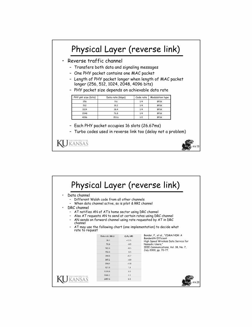
Physical Layer (reverse link)• Reverse traffic channel
– Transfers both data and signaling messages– One PHY packet contains one MAC packet– Length of PHY packet longer when length of MAC packet
longer (256, 512, 1024, 2048, 4096 bits)– PHY packet size depends on achievable data rate
– Each PHY packet occupies 16 slots (26.67ms)– Turbo codes used in reverse link too (delay not a problem)
BPSK1/476.82048
BPSK1/2153.64096
BPSK1/438.41024
BPSK1/419.2512
BPSK1/49.6256
Modulation typeCode rateData rate (kbps)PHY pkt size (bits)
#14 20
Physical Layer (reverse link)• Data channel
– Different Walsh code from all other channels– When data channel active, so is pilot & RRI channel
• DRC channel– AT notifies AN of AT’s home sector using DRC channel– Also AT requests AN to send at certain rates using DRC channel– AN sends on forward channel using rate requested by AT in DRC
channel– AT may use the following chart (one implementation) to decide what
rate to requestBender, P., et al., “CDMA/HDR: A Bandwidth EfficientHigh Speed Wireless Data Service for Nomadic Users,” IEEE Communications, Vol. 38, No. 7, July 2000, pp. 70-77.
#14 21
Physical Layer (reverse link)
• Reverse rate indicator channel– Tells AN of the rate at which packet are sent in reverse-
link data channel – 6 possible rates (including 0 Kbps)– Tell AN once every PHY packet (16 slots) so AN knows
what rate data is coming at• ACK channel
– ACK/NACK a forward channel PHY packet based on CRC check success/failure
• Access channel– Used by AT to first contact AN– Rate fixed at 9.6 Kbps (access packet always 256 bits)– Access probe carries PHY access packet
#14 22
Power control (reverse link)• On reverse link, pilot channel, data channel, DRC
channel and ACK channel are power controlled• Both open-loop and closed-loop power control used• Open-loop power control
– AT receives forward pilot channel– AT uses this to compute mean output power in reverse link– Lower the received power of forward channel pilot, higher
is the open-loop mean output power of reverse channels– Reverse link power also function of transmission rate
• AT needs higher power to transmit at 153.6 than at 9.6 Kbps• Closed-loop power control
– AT receives power control bits from AN on RPC channel– AT changes mean output power based on these bits– AN has Eb/N0 threshold
• If received power less than threshold, send “power up” to AT• If received power more than threshold, send “power down”• Threshold is computed dynamically at AN
#14 23
Adaptive modulation and coding• Channel is time-varying: mobility, fading, etc.• If adaptive modulation/coding not used then either
– Design modulation/coding conservatively for good link quality but then high data rates cannot be achieved
– Or design modulation/coding for high data rate but then link quality is low
• Adaptive: match transmission parameters to channel– Improves spectrum efficiency, system performance
• In EV-DO systems, AT reports DRC (based on SNR) in every time-slot (1.667 ms)
• AN uses this information to chose suitable modulation and coding for that time-slot (target packet error rate at less than 1%)
#14 24
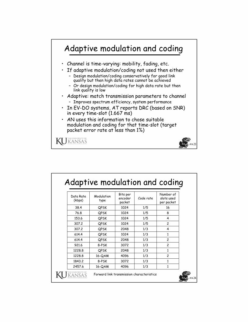
Adaptive modulation and coding
11/3409616-QAM2457.611/330728-PSK1843.221/3409616-QAM1228.811/32048QPSK1228.821/330728-PSK921.621/32048QPSK614.411/31024QPSK614.441/32048QPSK307.221/51024QPSK307.241/51024QPSK153.6 81/51024QPSK76.8161/51024QPSK38.4
Number of slots used per packet
Code rateBits per encoder packet
Modulation type
Data Rate (kbps)
Forward link transmission characteristics
#14 25
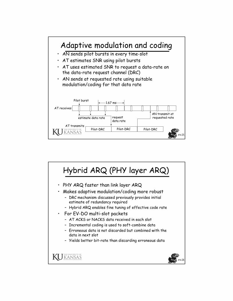
Adaptive modulation and coding• AN sends pilot bursts in every time-slot• AT estimates SNR using pilot bursts• AT uses estimated SNR to request a data-rate on
the data-rate request channel (DRC)• AN sends at requested rate using suitable
modulation/coding for that data rate
estimate data rate request data rate
AN transmit at requested rate
Pilot-DRC Pilot-DRC Pilot-DRC
Pilot burst1.67 ms
AT receives
AT transmits
#14 26
Hybrid ARQ (PHY layer ARQ)
• PHY ARQ faster than link layer ARQ• Makes adaptive modulation/coding more robust
– DRC mechanism discussed previously provides initial estimate of redundancy required
– Hybrid ARQ enables fine tuning of effective code rate• For EV-DO multi-slot packets
– AT ACKS or NACKS data received in each slot– Incremental coding is used to soft-combine data – Erroneous data is not discarded but combined with the
data in next slot– Yields better bit-rate than discarding erroneous data
#14 27
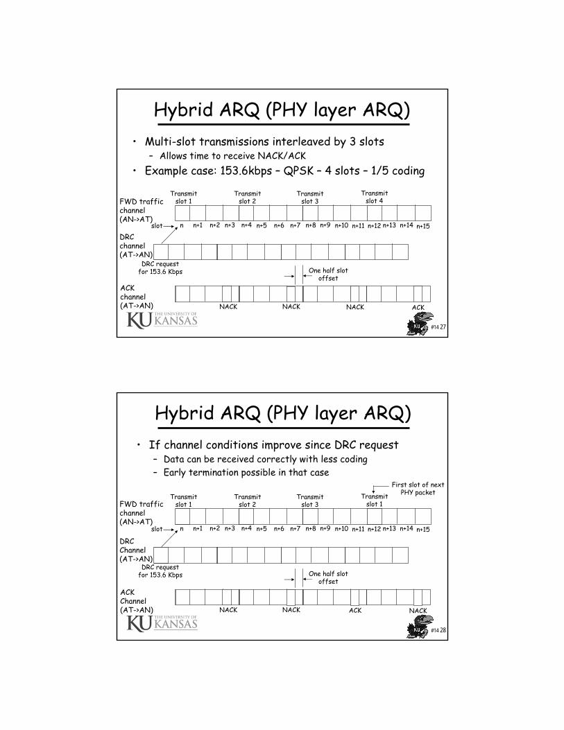
Hybrid ARQ (PHY layer ARQ)• Multi-slot transmissions interleaved by 3 slots
– Allows time to receive NACK/ACK• Example case: 153.6kbps – QPSK – 4 slots – 1/5 coding
FWD trafficchannel(AN->AT)
DRC channel(AT->AN)
ACKchannel(AT->AN)
n n+1 n+2 n+3 n+4 n+5 n+6 n+7 n+8 n+9 n+10 n+11 n+12 n+13 n+14 n+15slot
DRC requestfor 153.6 Kbps
Transmitslot 1
Transmitslot 2
Transmitslot 3
Transmitslot 4
One half slotoffset
NACK NACK NACK ACK
#14 28
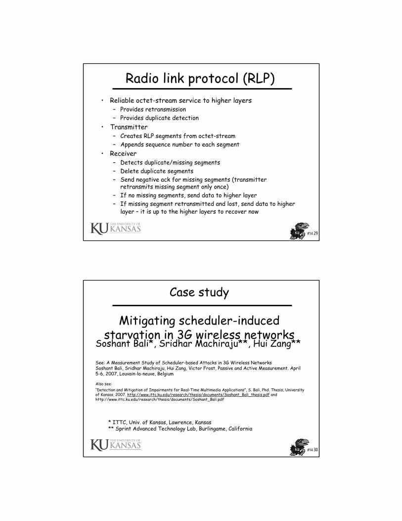
Hybrid ARQ (PHY layer ARQ)• If channel conditions improve since DRC request
– Data can be received correctly with less coding– Early termination possible in that case
FWD trafficchannel(AN->AT)
DRC Channel(AT->AN)
ACKChannel(AT->AN)
n n+1 n+2 n+3 n+4 n+5 n+6 n+7 n+8 n+9 n+10 n+11 n+12 n+13 n+14 n+15slot
DRC requestfor 153.6 Kbps
Transmitslot 1
Transmitslot 2
Transmitslot 3
Transmitslot 1
One half slotoffset
NACK NACK ACK NACK
First slot of nextPHY packet
#14 29
Radio link protocol (RLP)• Reliable octet-stream service to higher layers
– Provides retransmission – Provides duplicate detection
• Transmitter– Creates RLP segments from octet-stream– Appends sequence number to each segment
• Receiver– Detects duplicate/missing segments– Delete duplicate segments– Send negative ack for missing segments (transmitter
retransmits missing segment only once)– If no missing segments, send data to higher layer– If missing segment retransmitted and lost, send data to higher
layer – it is up to the higher layers to recover now
#14 30
Case study
Mitigating scheduler-induced starvation in 3G wireless networks
Soshant Bali*, Sridhar Machiraju**, Hui Zang**
See: A Measurement Study of Scheduler-based Attacks in 3G Wireless NetworksSoshant Bali, Sridhar Machiraju, Hui Zang, Victor Frost, Passive and Active Measurement. April 5-6, 2007, Louvain-la-neuve, Belgium
Also see:“Detection and Mitigation of Impairments for Real-Time Multimedia Applications”, S. Bali, Phd. Thesis, University of Kansas, 2007. http://www.ittc.ku.edu/research/thesis/documents/Soshant_Bali_thesis.pdf and http://www.ittc.ku.edu/research/thesis/documents/Soshant_Bali.pdf
* ITTC, Univ. of Kansas, Lawrence, Kansas** Sprint Advanced Technology Lab, Burlingame, California
#14 31
Outline
• Introduction• Problem: PF with on-off traffic
– High jitter– Throughput reduction– Increased flow completion time
• Solution– Parallel PF– Shrinking alpha
#14 32
Introduction• 3G-wireless widely deployed• Sprint and Verizon use 1xEV-DO
– 1x Evolution for Data Optimized– Up to 2.45Mbps downlink, 153.6Kbps uplink– Natural evolution from IS-95, IS-2000– Evolution: leverage existing network elements– Optimized for data transfer
• Data service characteristics– Rates asymmetric
• EV-DO: higher rate in forward link – Latency can be tolerated
• EV-DO: uses link layer ARQ• EV-DO: powerful error-correcting codes (e.g., turbo codes)• PHY packet error rate < 1%, ARQ on top of that = Reliable link
– Transmissions are in burst• EV-DO: uses time-division multiplexing
#14 33
Introduction• Scheduler
– Time divided into time-slots– Scheduling problem: Base station has to decide which
mobile it should send data to in next time slot– EV-DO and HSDPA use PF scheduler
• Channel-aware scheduler• Improves system throughput• Very well researched, shown to have very good performance• Widely deployed (all major vendors implement and
recommend using this algorithm)• Contribution
– PF scheduler can easily lead to starvation of mobiles• Deliberately (malicious user)• Accidentally (one mobile web browsing can cause
impairments to other mobile users) – Propose and evaluate starvation resistant scheduler
#14 34
EVDO: adaptive modulation/coding• Channel conditions are time-varying: mobility, fading, etc.• If adaptive modulation/coding not used then either
– Design modulation/coding conservatively for good link quality but then high data rates cannot be achieved
– Or design modulation/coding for high data rate but then link quality is low
• Adaptive: match transmission parameters to channel conditions– Improves spectrum efficiency, system performance
• AT measures SINR every time slot (1.67ms) and in determines suitable DRC (data rate control)
• AT reports DRC in every time-slot • AN uses this information to chose suitable modulation and
coding for that time-slot (target packet error rate is less than 1%)
#14 35
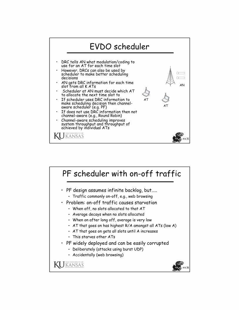
EVDO scheduler
• DRC tells AN what modulation/coding to use for an AT for each time slot
• However, DRCs can also be used by scheduler to make better scheduling decisions
• AN gets DRC information for each time slot from all K ATs
• Scheduler at AN must decide which AT to allocate the next time slot to
• If scheduler uses DRC information to make scheduling decision then channel-aware scheduler (e.g. PF)
• If does not use DRC information then not channel-aware (e.g., Round Robin)
• Channel-aware scheduling improves system throughput and throughput of achieved by individual ATs
AT
AT
AN
#14 36
PF scheduler with on-off traffic
• PF design assumes infinite backlog, but…..– Traffic commonly on-off, e.g., web browsing
• Problem: on-off traffic causes starvation– When off, no slots allocated to that AT– Average decays when no slots allocated– When on after long off, average is very low– AT that goes on has highest R/A amongst all ATs (low A)– AT that goes on gets all slots until A increases– This starves other ATs
• PF widely deployed and can be easily corrupted– Deliberately (attacks using burst UDP)– Accidentally (web browsing)
#14 37
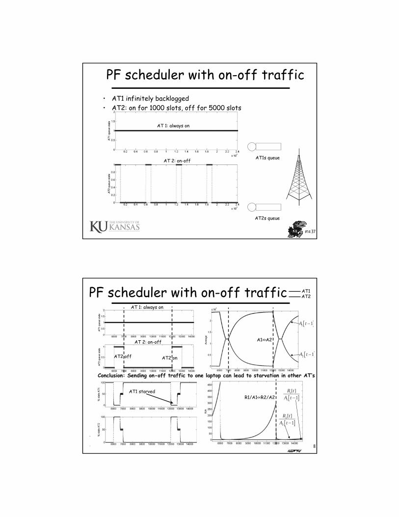
PF scheduler with on-off traffic• AT1 infinitely backlogged• AT2: on for 1000 slots, off for 5000 slots
AT1s queue
AT2s queue
AT 1: always on
AT 2: on-off
#14 38
PF scheduler with on-off traffic
AT1 starved
AT1AT2
AT 1: always on
AT 2: on-off
[ ]1 1A t −
[ ]2 1A t −
[ ]1
1
[ ]1
R tA t −
[ ]2
2
[ ]1
R tA t −
AT2 off AT2 on
A1>>A2
R1/A1<<R2/A2
Conclusion: Sending on-off traffic to one laptop can lead to starvation in other AT’s
#14 39
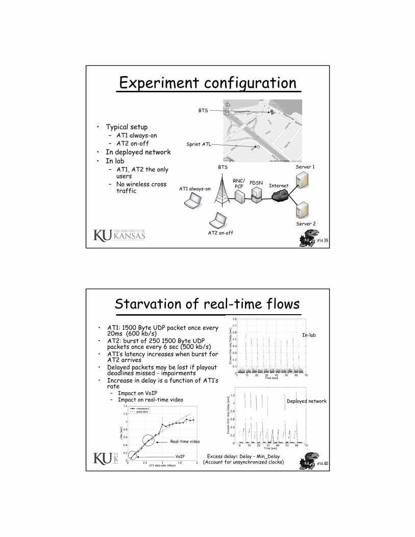
Experiment configuration
AT1 always-on
AT2 on-off
BTS
RNC/PCF
PDSN Internet
Server 1
Server 2
• Typical setup– AT1 always-on– AT2 on-off
• In deployed network• In lab
– AT1, AT2 the only users
– No wireless cross traffic
BTS
Sprint ATL
#14 40
Starvation of real-time flows• AT1: 1500 Byte UDP packet once every
20ms (600 kb/s)• AT2: burst of 250 1500 Byte UDP
packets once every 6 sec (500 kb/s)• AT1’s latency increases when burst for
AT2 arrives• Delayed packets may be lost if playout
deadlines missed - impairments• Increase in delay is a function of AT1’s
rate– Impact on VoIP– Impact on real-time video
In-lab
Deployed network
VoIP
Real-time video
Excess delay= Delay – Min_Delay(Account for unsynchronized clocks)
#14 41
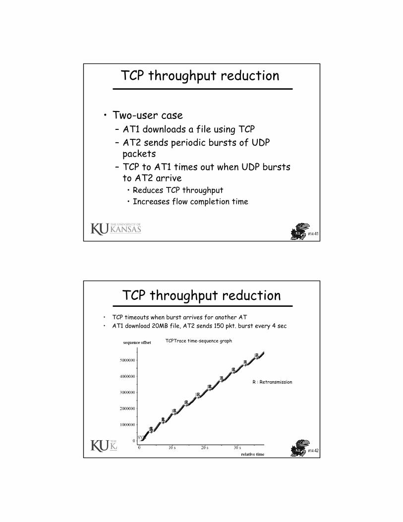
TCP throughput reduction
• Two-user case– AT1 downloads a file using TCP– AT2 sends periodic bursts of UDP
packets– TCP to AT1 times out when UDP bursts
to AT2 arrive• Reduces TCP throughput• Increases flow completion time
#14 42
TCP throughput reduction• TCP timeouts when burst arrives for another AT• AT1 download 20MB file, AT2 sends 150 pkt. burst every 4 sec
TCPTrace time-sequence graph
R : Retransmission

#14 43
TCP throughput reduction: long flows• AT1 downloads 20 MB file (using TCP), AT2 sends cbr or bursty
UDP traffic; burst size = 150 packets• Which inter-burst gap has maximum impact with minimal overhead?
#14 44
TCP throughput reduction: long flows• AT1 downloads 20 MB file, AT2 sends cbr or bursty UDP traffic;
burst size = variable, interval burst gap = 3 s• Which burst size has maximum impact with minimum overhead?
#14 45
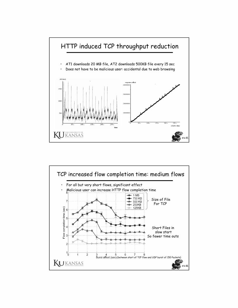
HTTP induced TCP throughput reduction
• AT1 downloads 20 MB file, AT2 downloads 500KB file every 15 sec• Does not have to be malicious user: accidental due to web browsing
#14 46
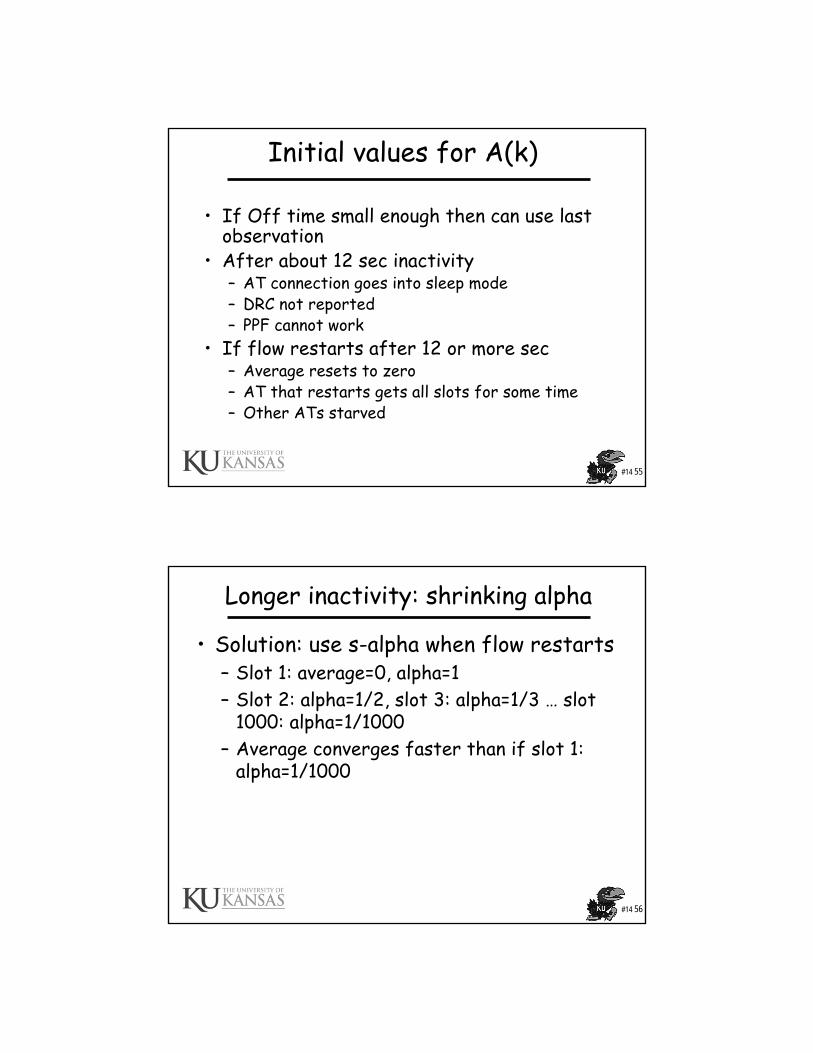
TCP increased flow completion time: medium flows
• For all but very short flows, significant effect• Malicious user can increase HTTP flow completion time
(between start of TCP flow and UDP burst of 150 Packets)
Size of FileFor TCP
Short Files in slow start
So fewer time outs
#14 47
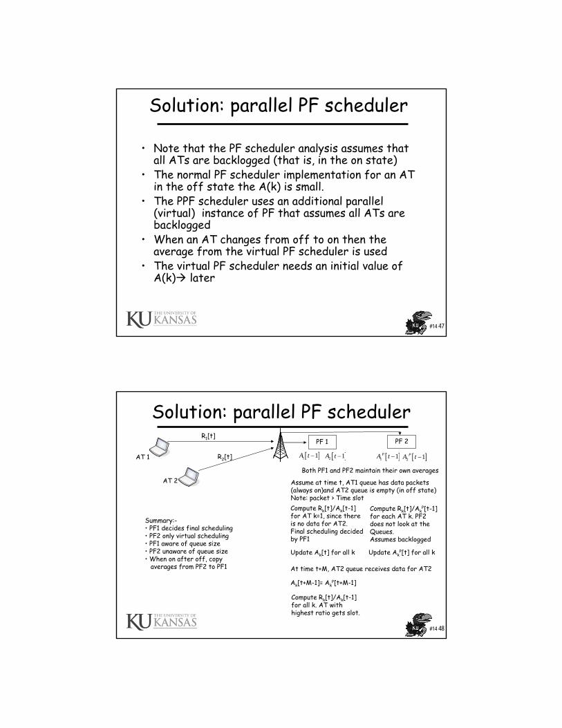
Solution: parallel PF scheduler
• Note that the PF scheduler analysis assumes that all ATs are backlogged (that is, in the on state)
• The normal PF scheduler implementation for an AT in the off state the A(k) is small.
• The PPF scheduler uses an additional parallel (virtual) instance of PF that assumes all ATs are backlogged
• When an AT changes from off to on then the average from the virtual PF scheduler is used
• The virtual PF scheduler needs an initial value of A(k) later
#14 48
Solution: parallel PF scheduler
AT 1
AT 2
PF 1 PF 2
[ ]1 1A t − [ ]2 1A t − [ ]1 1PA t − [ ]2 1PA t −
Both PF1 and PF2 maintain their own averages
R1[t]
R2[t]
Compute Rk[t]/Ak[t-1]for AT k=1, since thereis no data for AT2. Final scheduling decidedby PF1
Compute Rk[t]/AkP[t-1]
for each AT k. PF2does not look at the Queues. Assumes backlogged
Assume at time t, AT1 queue has data packets(always on)and AT2 queue is empty (in off state) Note: packet > Time slot
Update Ak[t] for all k Update AkP[t] for all k
At time t+M, AT2 queue receives data for AT2
Ak[t+M-1]= AkP[t+M-1]
Compute Rk[t]/Ak[t-1]for all k. AT with highest ratio gets slot.
Summary:-• PF1 decides final scheduling• PF2 only virtual scheduling• PF1 aware of queue size• PF2 unaware of queue size• When on after off, copy
averages from PF2 to PF1
#14 49
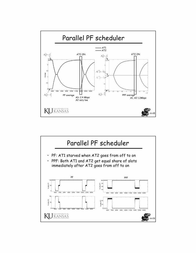
Parallel PF scheduler
PF average PPF average
AT1AT2
[ ]1 1A t −
[ ]2 1A t −
[ ]1 1A t −
[ ]2 1A t −
[ ]2 1PA t −
[ ]1 1PA t −
AT2 ON
A1= 2.4 MbpsA2 very low
AT2 ON
A1, A2 1.2Mbps
#14 50
Parallel PF scheduler
• PF: AT1 starved when AT2 goes from off to on• PPF: Both AT1 and AT2 get equal share of slots
immediately after AT2 goes from off to on
PF PPF
#14 51
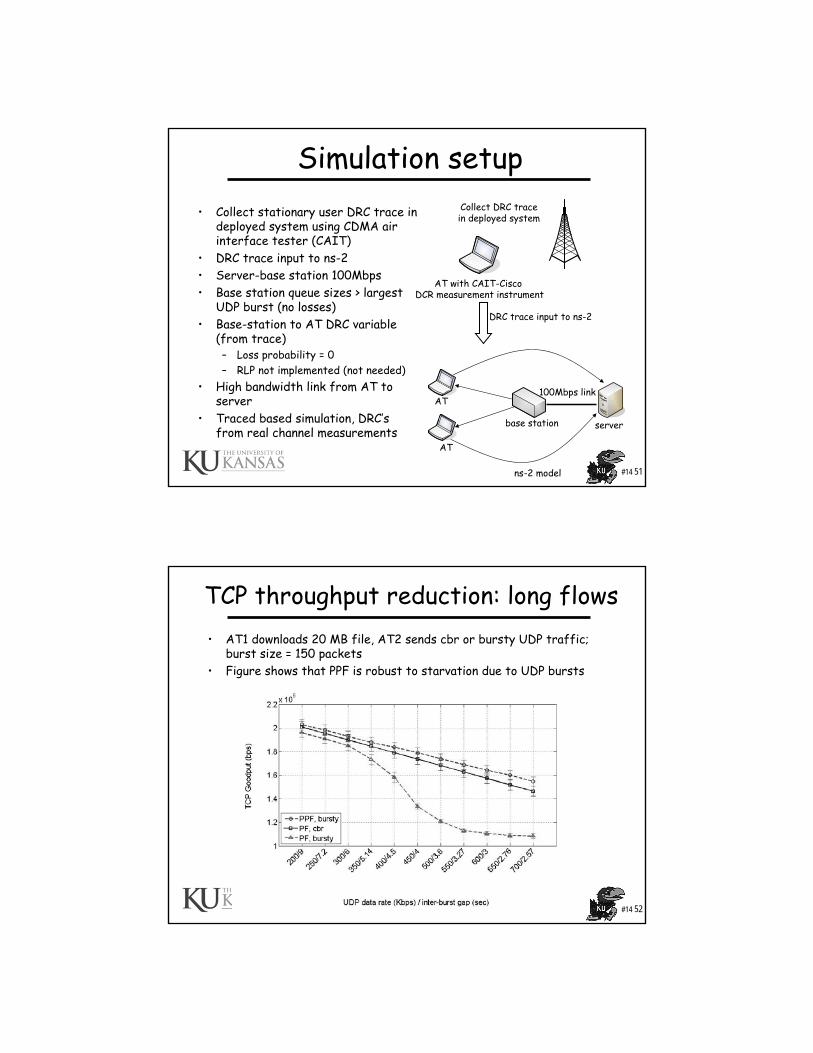
Simulation setup • Collect stationary user DRC trace in
deployed system using CDMA air interface tester (CAIT)
• DRC trace input to ns-2• Server-base station 100Mbps• Base station queue sizes > largest
UDP burst (no losses)• Base-station to AT DRC variable
(from trace)– Loss probability = 0– RLP not implemented (not needed)
• High bandwidth link from AT to server
• Traced based simulation, DRC’sfrom real channel measurements
base station server
AT
AT100Mbps link
AT with CAIT-Cisco DCR measurement instrument
Collect DRC tracein deployed system
DRC trace input to ns-2
ns-2 model
#14 52
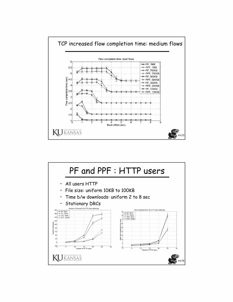
TCP throughput reduction: long flows• AT1 downloads 20 MB file, AT2 sends cbr or bursty UDP traffic;
burst size = 150 packets• Figure shows that PPF is robust to starvation due to UDP bursts
#14 53
TCP increased flow completion time: medium flows
#14 54
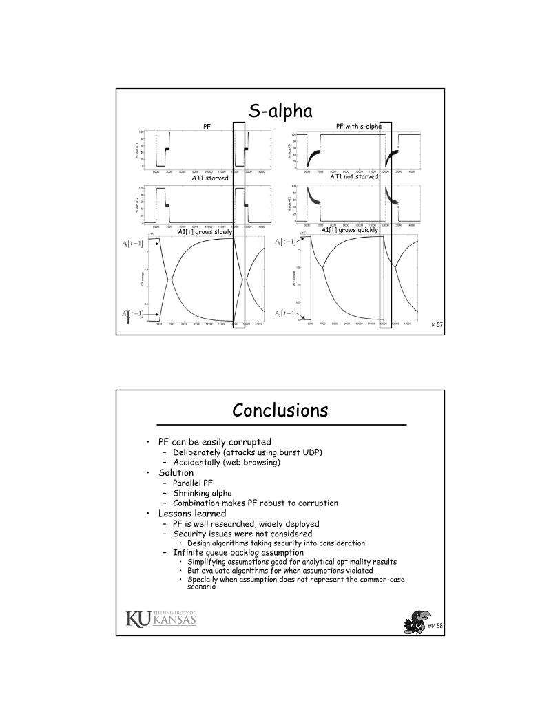
PF and PPF : HTTP users• All users HTTP• File size: uniform 10KB to 100KB• Time b/w downloads: uniform 2 to 8 sec• Stationary DRCs
#14 55
Initial values for A(k)
• If Off time small enough then can use last observation
• After about 12 sec inactivity– AT connection goes into sleep mode– DRC not reported– PPF cannot work
• If flow restarts after 12 or more sec– Average resets to zero– AT that restarts gets all slots for some time– Other ATs starved
#14 56
Longer inactivity: shrinking alpha
• Solution: use s-alpha when flow restarts– Slot 1: average=0, alpha=1– Slot 2: alpha=1/2, slot 3: alpha=1/3 … slot
1000: alpha=1/1000– Average converges faster than if slot 1:
alpha=1/1000
#14 57
S-alpha
[ ]1 1A t −
[ ]2 1A t −
[ ]1 1A t −
[ ]2 1A t −
PF PF with s-alpha
A1[t] grows slowly
AT1 starved
A1[t] grows quickly
AT1 not starved
#14 58
Conclusions• PF can be easily corrupted
– Deliberately (attacks using burst UDP)– Accidentally (web browsing)
• Solution– Parallel PF– Shrinking alpha – Combination makes PF robust to corruption
• Lessons learned– PF is well researched, widely deployed– Security issues were not considered
• Design algorithms taking security into consideration– Infinite queue backlog assumption
• Simplifying assumptions good for analytical optimality results• But evaluate algorithms for when assumptions violated• Specially when assumption does not represent the common-case
scenario
#14 59
References• TIA/EIA/IS-856, cdma2000 High Rate Packet Data Air Interface
Specification, Telecommunications Industry Association, January 2002.
• Samuel C. Yang, “3G CDMA 2000: Wireless System Engineering,” Artech House Inc.
• Kamran Etemad, “CDMA 2000 Evolution,” John Wiley and Sons Inc., 2004
• Mooi Choo Chuah and QinQing Zhnag, “Design and Performance of 3G Wireless Networks and Wireless LANs,” Springer Inc., 2006.
• Bender, P., et al., “CDMA/HDR: A Bandwidth Efficient High Speed Wireless Data Service for Nomadic Users,” IEEE Communications, Vol. 38, No. 7, July 2000, pp. 70-77.
• Soshant Bali, Sridhar Machiraju, Hui Zang, Victor Frost, “A Measurement Study of Scheduler-based Attacks in 3G Wireless Networks, Passive and Active Measurement,” April 5-6, 2007, Louvain-la-neuve, Belgium