132228833 seminar on steel plate shear wall
TRANSCRIPT
REPORT ON
STEEL PLATE SHEAR
WALL PRACTICAL DESIGN AND CONSTRUCTION
Guided by: Submitted by:
Prof.P.G.Patel Nilesh H. Saksena
EN.NO.:110280715004
Applied mechanics department
L.D.College of engineering
AHMEDABAD-15
Steel plate shear wall
2
INDEX
SR.NO. TITLE
1. INTRODUCTION
2. SYSTEMS OF STEEL PLATE SHEAR WALL
3. ADVANTAGED OF STEEL PLATE SHEAR
WALL
4. DISADVANTAGES OF STEEL PLATE
SHEAR WALL
5. USE OF STEEL PLATE SHEAR WALL AND
THEIR SESMIC BEHAVIOUR
6. ANALYSIS AND DESIGN APPROACH
7. CONSRUCTION CONSIDERATIONS
Steel plate shear wall
3
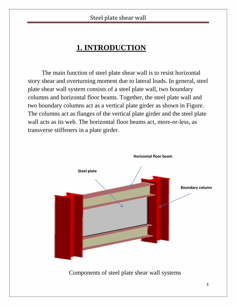
1. INTRODUCTION
The main function of steel plate shear wall is to resist horizontal
story shear and overturning moment due to lateral loads. In general, steel
plate shear wall system consists of a steel plate wall, two boundary
columns and horizontal floor beams. Together, the steel plate wall and
two boundary columns act as a vertical plate girder as shown in Figure.
The columns act as flanges of the vertical plate girder and the steel plate
wall acts as its web. The horizontal floor beams act, more-or-less, as
transverse stiffeners in a plate girder.
Components of steel plate shear wall systems
Steel plate
Horizontal floor beam
Boundary column
Steel plate shear wall
4
2.SYSTEMS OF STEEL PLATE SHEAR WALL:
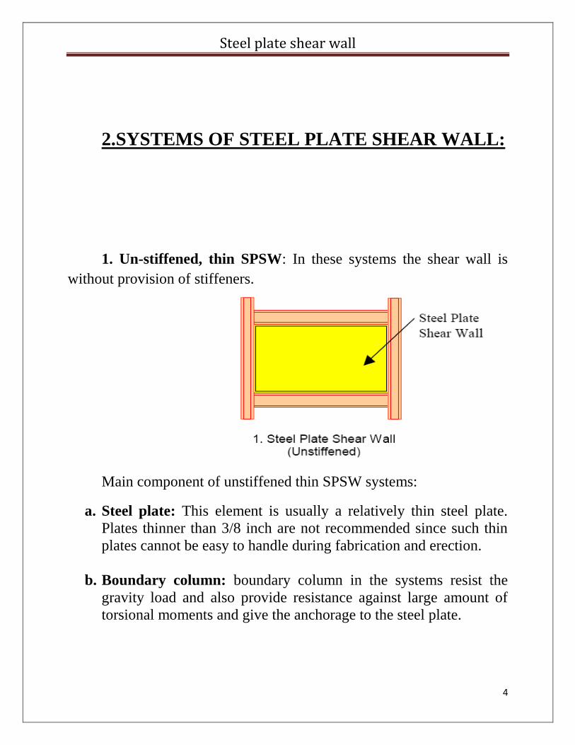
1. Un-stiffened, thin SPSW: In these systems the shear wall is
without provision of stiffeners.
Main component of unstiffened thin SPSW systems:
a. Steel plate: This element is usually a relatively thin steel plate.
Plates thinner than 3/8 inch are not recommended since such thin
plates cannot be easy to handle during fabrication and erection.
b. Boundary column: boundary column in the systems resist the
gravity load and also provide resistance against large amount of
torsional moments and give the anchorage to the steel plate.
Steel plate shear wall
5
c. Horizontal floor beams: The top and bottom beams in a shear
wall act as anchor for tension field action of the steel plate and also
provide support to the floor.
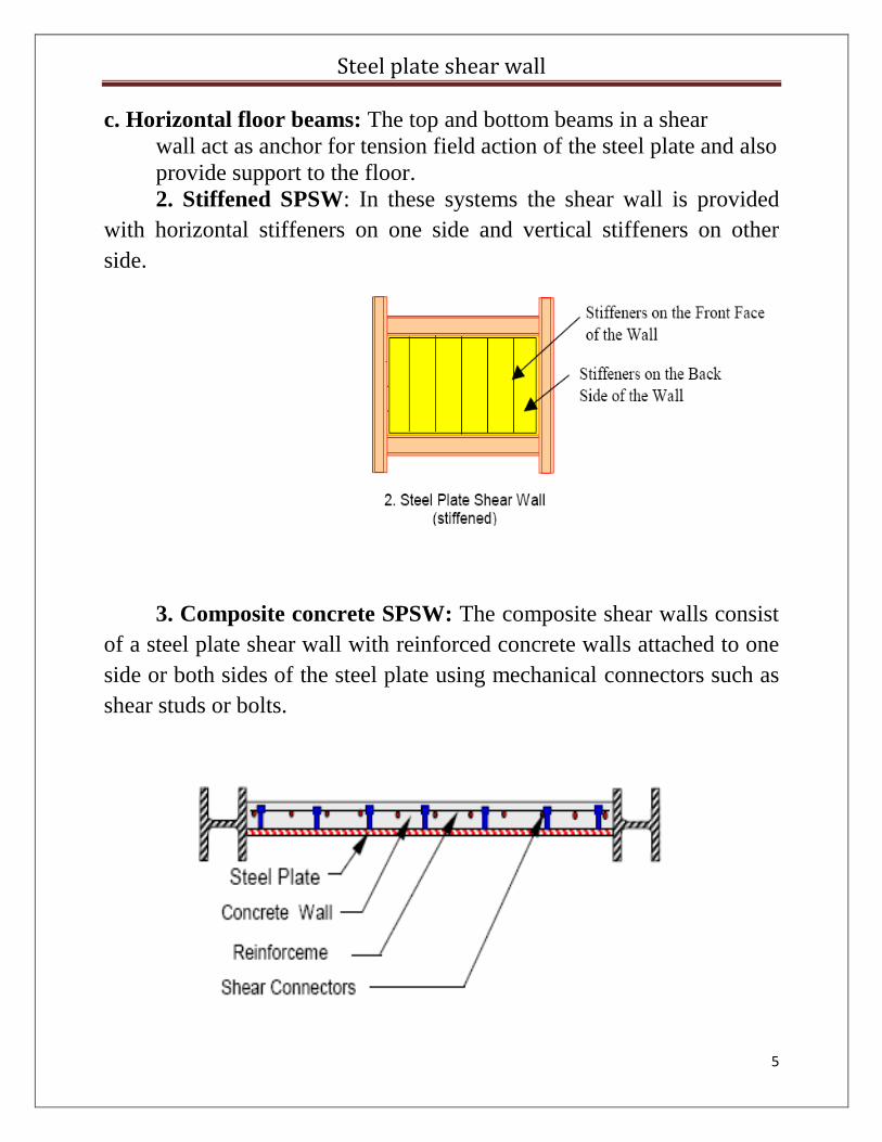
2. Stiffened SPSW: In these systems the shear wall is provided
with horizontal stiffeners on one side and vertical stiffeners on other
side.
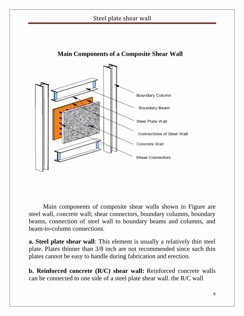
3. Composite concrete SPSW: The composite shear walls consist
of a steel plate shear wall with reinforced concrete walls attached to one
side or both sides of the steel plate using mechanical connectors such as
shear studs or bolts.
Steel plate shear wall
6
Main Components of a Composite Shear Wall
Main components of composite shear walls shown in Figure are
steel wall, concrete wall; shear connectors, boundary columns, boundary
beams, connection of steel wall to boundary beams and columns, and
beam-to-column connections.
a. Steel plate shear wall: This element is usually a relatively thin steel
plate. Plates thinner than 3/8 inch are not recommended since such thin
plates cannot be easy to handle during fabrication and erection.
b. Reinforced concrete (R/C) shear wall: Reinforced concrete walls
can be connected to one side of a steel plate shear wall. the R/C wall
Steel plate shear wall
7
provides shear strength and stiffness, through its compression field and
some ductility depending on the amount of reinforcement in the wall.
c. Shear connectors: Shear connectors are used to connect steel
elements of the composite wall to concrete. For cast-in-place concrete
usually welded shear studs are used. Of course other shear connectors
such as channels can also be used although they may not be as
economical as welded shear studs. For pre-cast concrete walls, bolts can
be used to connect the R/C walls to steel plate walls
d. Boundary columns: In addition to gravity loads, the columns on the
sides of a composite shear wall resist the bulk of overturning moments.
The columns also provide an anchor point for tension field action of
the steel plate and bearing element for compression diagonal element of
the concrete wall. In structures with relatively large columns, the
columns can also transfer a considerable amount of story shear.
e. Boundary beams: The top and bottom beams in a composite shear
wall act as anchor for tension field action of the steel plate and as
compression bearing element for compression diagonal of the concrete
wall.
f. Connections of shear wall to boundary members: The steel shear
wall should be connected to boundary columns and beams either by
bolts or welds. The main role of these connections is to transfer shear
and tension. The concrete wall can also be connected to the boundary
walls using mechanical connectors. These connections transfer shear that
is resisted by the reinforcement inside the wall.
g. Beam-to-column connections: These connections play a major role
in performance of the walls. In a dual system, where the steel frame is
the “back-up” system for the composite shear wall, the connections
should be moment connections
Steel plate shear wall
8
3. ADVANTAGES OF STEEL PLATE SHEAR
WALL:
1. Wall Thickness. SPSW allow for less structural wall thickness in
comparison to the thickness of concrete shear walls. Astudy performed
for The Century project indicated an average wall thickness, including
the furring, of 18” as opposed to a concrete shear wall thickness with an
average of 28”. This resulted in a savings of approximately
2% in gross square footage.
2. Building Weight. SPSW result in ales ser building weight in
comparison to buildings that use concrete shear walls. A study
performed for The Century project indicated that the total weight of the
building as designed using SPSW was approximately 18% less than that
of the building designed using a concrete shear wall core system, which
results in a reduction of foundation loads due to gravity and overall
building seismic loads.
3.Fast Construction. The use of a SPSW system reduces construction
time. Not only is it fast to erect, but there also is no curing period. A
scheduling study performed by a contractor for The Century project
indicated a one-month reduction in construction time. The steel erector
for the U.S. Federal Courthouse indicated that the erection of the SPSW
was much easier than that of the special concentrically braced frames.
4. Ductility. A relatively thin steel plate has excellent post-buckling
capacity. Research performed on the SPSW system indicates that the
system can survive up to 4% drift without experiencing significant
damage, even though most of the tests showed damage outside
the steel plate panel. There was some pinching and tearing close to the
corners of the panel due to bending. However, this tearing did not reduce
the plate capacity and stiffness.
Steel plate shear wall
9
5. Tested System. At least two buildings that use SPSW as their primary
lateral force resisting system have undergone significant earthquake
ground shaking. Both buildings survived with insignificant insignificant
structural damage (Astaneh & Zhao, 2002). The system also has been
tested since the 1970s. The system has been recognized in the National
Building Code of Canada (NBCC) since 1994 and will be included in
the American Institute of Steel Construction (AISC) Seismic Provisions
in 2005.
Steel plate shear wall
10
4.DISADVANTAGES OF STEEL PLATE
SHEAR WALL:
1. Stiffness. SPSW systems are usually more flexible in comparison
to concrete shear walls, primarily due to their flexural flexibility.
Therefore, when using SPSW in tall buildings, the engineer must
Provide additional flexural stiffness. In both The Century and the
U.S. Federal Courthouse projects, large composite concrete infill
steel pipe columns were used at all corners of the core wall to
improve the System’s flexural stiffness as well as its overturning
capacity.
2. Construction Sequence. Excessive initial compressive force in
the steel plate panel may delay the development of the tension-
field action. It is important that the construction sequence be
designed to avoid excessive compression in the panel. In the U.S.
Federal Courthouse project, the welding of the plate splice
connections was delayed until most of the dead load deformation
occurred in order to relieve the pre-compression within the steel
plate shear wall panel.
3.New System. Due to unfamiliarity with the system, a contractor
will typically estimate a relatively high erected cost. This may be
solved by engaging the contractor early in the design phase.
Steel plate shear wall
11
5. USE OF STEEL SHEAR WALLS AND THEIR SEISMIC BEHAVIOR
Steel plate shear walls (SPSW) have been used, to a limited
extent, as the primary lateral force resisting system in buildings for more
than three decades. There have been numerous SPSW research programs
in this timeframe in the United States, Canada, and Japan to help foster a
better understanding of the system’s behavior, particularly as it relates
to earthquake-resistant design. Some major building projects that
utilized SPSW as the primary lateral force resisting system include the
following:
➜ United States Federal Courthouse, Seattle, WA— 23-story building
(350’)
➜ Sylmar Hospital, Los Angeles, CA— six-story building
➜ Canam-Manac Headquarters Expansion, St. George, Quebec— six-
story building
➜ Hyatt Regency Hotel at Reunion, Dallas, TX— 50-story building
(562’)
➜ The Century, San Francisco, CA— 46- story building (465’; the
project was cancelled after the completion of
design and permit)
➜ Nippon Steel Building, Tokyo, Japan— 20-story building
➜ Shinjuku Nomura Building, Tokyo, Japan— 51-story building (693’)
➜ Kobe Office Building, Kobe, Japan— 35-story building (425’)
Steel plate shear wall
12
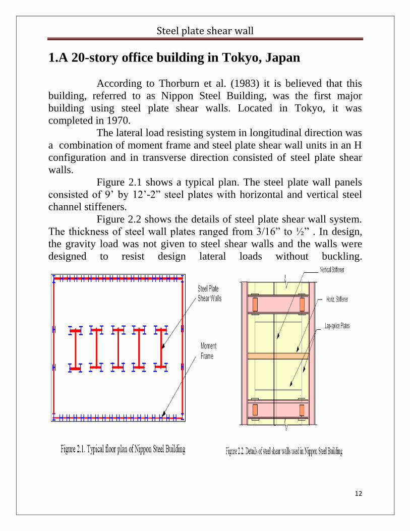
1.A 20-story office building in Tokyo, Japan
According to Thorburn et al. (1983) it is believed that this
building, referred to as Nippon Steel Building, was the first major
building using steel plate shear walls. Located in Tokyo, it was
completed in 1970.
The lateral load resisting system in longitudinal direction was
a combination of moment frame and steel plate shear wall units in an H
configuration and in transverse direction consisted of steel plate shear
walls.
Figure 2.1 shows a typical plan. The steel plate wall panels
consisted of 9’ by 12’-2” steel plates with horizontal and vertical steel
channel stiffeners.
Figure 2.2 shows the details of steel plate shear wall system.
The thickness of steel wall plates ranged from 3/16” to ½” . In design,
the gravity load was not given to steel shear walls and the walls were
designed to resist design lateral loads without buckling.
Steel plate shear wall
13
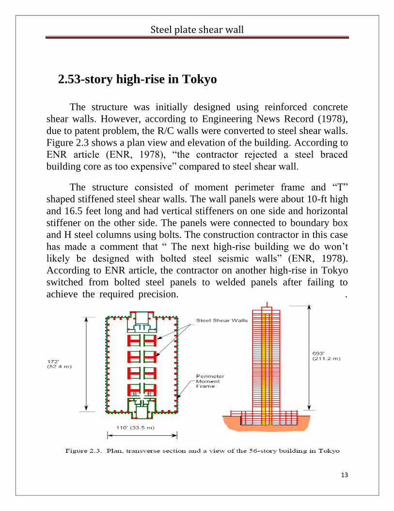
2.53-story high-rise in Tokyo
The structure was initially designed using reinforced concrete
shear walls. However, according to Engineering News Record (1978),
due to patent problem, the R/C walls were converted to steel shear walls.
Figure 2.3 shows a plan view and elevation of the building. According to
ENR article (ENR, 1978), “the contractor rejected a steel braced
building core as too expensive” compared to steel shear wall.
The structure consisted of moment perimeter frame and “T”
shaped stiffened steel shear walls. The wall panels were about 10-ft high
and 16.5 feet long and had vertical stiffeners on one side and horizontal
stiffener on the other side. The panels were connected to boundary box
and H steel columns using bolts. The construction contractor in this case
has made a comment that “ The next high-rise building we do won’t
likely be designed with bolted steel seismic walls” (ENR, 1978).
According to ENR article, the contractor on another high-rise in Tokyo
switched from bolted steel panels to welded panels after failing to
achieve the required precision. .
Steel plate shear wall
14
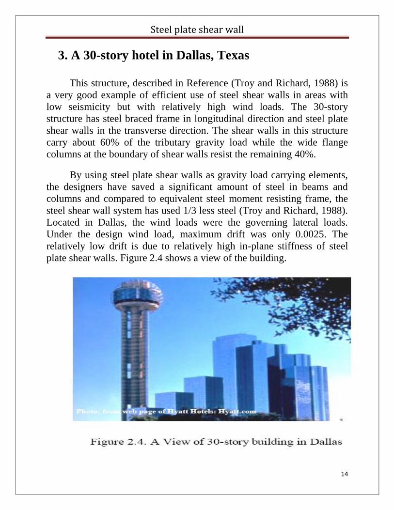
3. A 30-story hotel in Dallas, Texas
This structure, described in Reference (Troy and Richard, 1988) is
a very good example of efficient use of steel shear walls in areas with
low seismicity but with relatively high wind loads. The 30-story
structure has steel braced frame in longitudinal direction and steel plate
shear walls in the transverse direction. The shear walls in this structure
carry about 60% of the tributary gravity load while the wide flange
columns at the boundary of shear walls resist the remaining 40%.
By using steel plate shear walls as gravity load carrying elements,
the designers have saved a significant amount of steel in beams and
columns and compared to equivalent steel moment resisting frame, the
steel shear wall system has used 1/3 less steel (Troy and Richard, 1988).
Located in Dallas, the wind loads were the governing lateral loads.
Under the design wind load, maximum drift was only 0.0025. The
relatively low drift is due to relatively high in-plane stiffness of steel
plate shear walls. Figure 2.4 shows a view of the building.
Steel plate shear wall
15
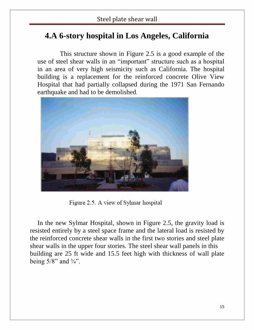
4.A 6-story hospital in Los Angeles, California
This structure shown in Figure 2.5 is a good example of the
use of steel shear walls in an “important” structure such as a hospital
in an area of very high seismicity such as California. The hospital
building is a replacement for the reinforced concrete Olive View
Hospital that had partially collapsed during the 1971 San Fernando
earthquake and had to be demolished.
In the new Sylmar Hospital, shown in Figure 2.5, the gravity load is
resisted entirely by a steel space frame and the lateral load is resisted by
the reinforced concrete shear walls in the first two stories and steel plate
shear walls in the upper four stories. The steel shear wall panels in this
building are 25 ft wide and 15.5 feet high with thickness of wall plate
being 5/8” and ¾”.
Steel plate shear wall
16
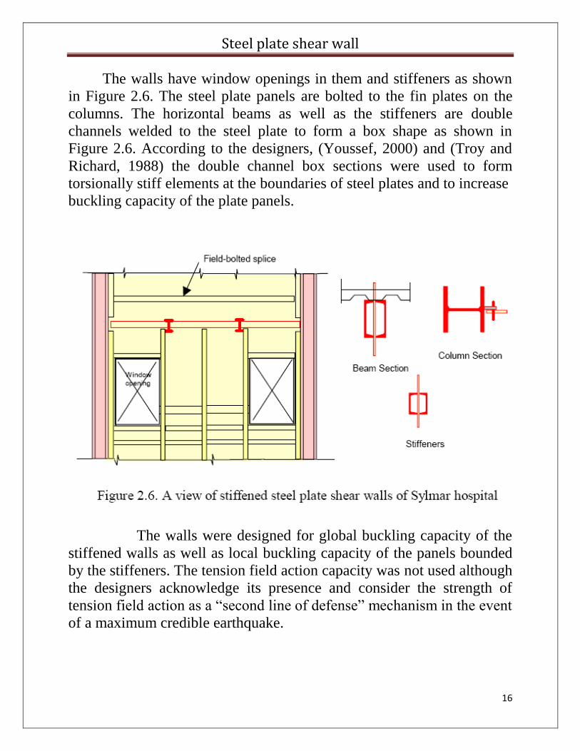
The walls have window openings in them and stiffeners as shown
in Figure 2.6. The steel plate panels are bolted to the fin plates on the
columns. The horizontal beams as well as the stiffeners are double
channels welded to the steel plate to form a box shape as shown in
Figure 2.6. According to the designers, (Youssef, 2000) and (Troy and
Richard, 1988) the double channel box sections were used to form
torsionally stiff elements at the boundaries of steel plates and to increase
buckling capacity of the plate panels.
The walls were designed for global buckling capacity of the
stiffened walls as well as local buckling capacity of the panels bounded
by the stiffeners. The tension field action capacity was not used although
the designers acknowledge its presence and consider the strength of
tension field action as a “second line of defense” mechanism in the event
of a maximum credible earthquake.
Steel plate shear wall
17
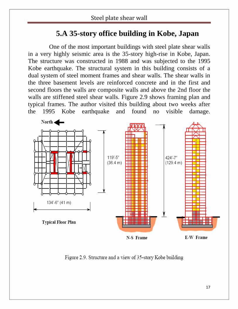
5.A 35-story office building in Kobe, Japan
One of the most important buildings with steel plate shear walls
in a very highly seismic area is the 35-story high-rise in Kobe, Japan.
The structure was constructed in 1988 and was subjected to the 1995
Kobe earthquake. The structural system in this building consists of a
dual system of steel moment frames and shear walls. The shear walls in
the three basement levels are reinforced concrete and in the first and
second floors the walls are composite walls and above the 2nd floor the
walls are stiffened steel shear walls. Figure 2.9 shows framing plan and
typical frames. The author visited this building about two weeks after
the 1995 Kobe earthquake and found no visible damage.
Steel plate shear wall
18
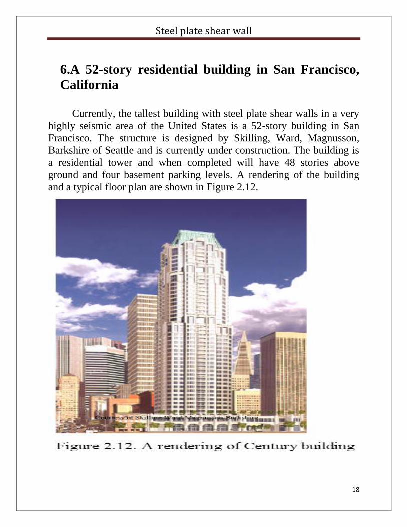
6.A 52-story residential building in San Francisco,
California
Currently, the tallest building with steel plate shear walls in a very
highly seismic area of the United States is a 52-story building in San
Francisco. The structure is designed by Skilling, Ward, Magnusson,
Barkshire of Seattle and is currently under construction. The building is
a residential tower and when completed will have 48 stories above
ground and four basement parking levels. A rendering of the building
and a typical floor plan are shown in Figure 2.12.
Steel plate shear wall
19
The gravity load carrying system in this building consists of four
large concrete-filled steel tubes at the core and sixteen concrete-filled
smaller steel tube columns in the perimeter. The floors outside the core
consist of post-tensioned flat slabs and inside the core and lower floors
are typical composite steel deck-concrete slab. The foundation consists
of a single reinforced concrete mat foundation.
The main lateral load resisting system of the structure consists of a
core made of four large concrete field steel tubes, one at each corner of
the core, and steel shear walls and coupling beams. There are built-up H
columns between the two corner pipe columns. The steel shear walls
are connected to concrete filled steel tubes by coupling beams. The shear
wall units are primarily shop-welded and bolt spliced at the site at each
floor mid-height. The only field welding is the connection of the girders
and steel plate shear wall to the large concrete-filled steel tube columns.
Steel plate shear wall
20
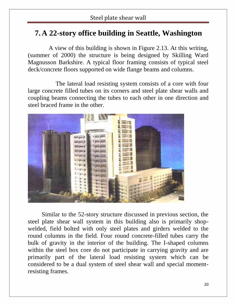
7. A 22-story office building in Seattle, Washington
A view of this building is shown in Figure 2.13. At this writing,
(summer of 2000) the structure is being designed by Skilling Ward
Magnusson Barkshire. A typical floor framing consists of typical steel
deck/concrete floors supported on wide flange beams and columns.
The lateral load resisting system consists of a core with four
large concrete filled tubes on its corners and steel plate shear walls and
coupling beams connecting the tubes to each other in one direction and
steel braced frame in the other.
Similar to the 52-story structure discussed in previous section, the
steel plate shear wall system in this building also is primarily shop-
welded, field bolted with only steel plates and girders welded to the
round columns in the field. Four round concrete-filled tubes carry the
bulk of gravity in the interior of the building. The I-shaped columns
within the steel box core do not participate in carrying gravity and are
primarily part of the lateral load resisting system which can be
considered to be a dual system of steel shear wall and special moment-
resisting frames.
Steel plate shear wall
21
6. ANALYSIS AND DESIGN APPROACH
The typical SPSW system is comprised of steel plate panels,
vertical boundary elements, and horizontal boundary elements.
The general procedure in the design of the SPSW system is as follows:
1. Gravity Framing:
The building frames, including the SPSW boundary elements, should
be designed to carry gravity loadings while neglecting the contribution
of the SPSW panels. This is an important factor, done to ensure that the
building frames have sufficient capacity to support the gravity loads
during seismic events, during which the plate experiences buckling due
to the development of its tension field action
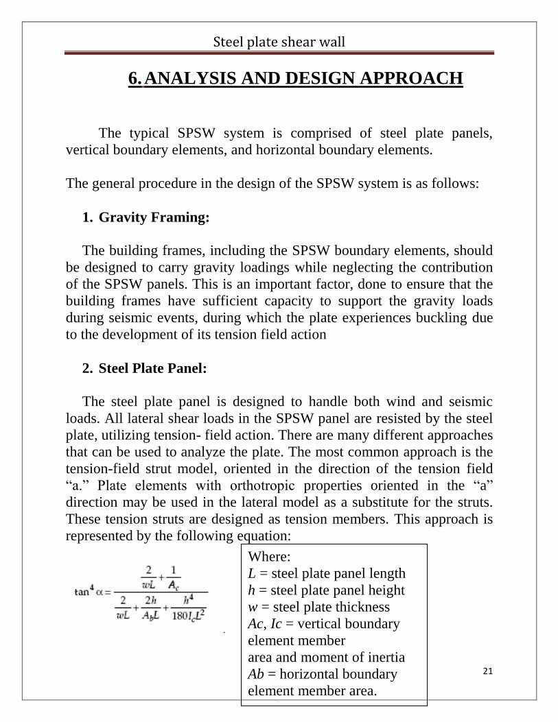
2. Steel Plate Panel:
The steel plate panel is designed to handle both wind and seismic
loads. All lateral shear loads in the SPSW panel are resisted by the steel
plate, utilizing tension- field action. There are many different approaches
that can be used to analyze the plate. The most common approach is the
tension-field strut model, oriented in the direction of the tension field
“a.” Plate elements with orthotropic properties oriented in the “a”
direction may be used in the lateral model as a substitute for the struts.
These tension struts are designed as tension members. This approach is
represented by the following equation:
.
Where:
L = steel plate panel length
h = steel plate panel height
w = steel plate thickness
Ac, Ic = vertical boundary
element member
area and moment of inertia
Ab = horizontal boundary
element member area.
member area
Steel plate shear wall
22
The suggested maximum height/length aspect ratio (h/L) is 1. A
large height/length ratio means the vertical boundary elements’ stiffness
and capacity will have more influence on the system quality. The
suggested minimum length/thickness ratio is 180. Thicker plates will
delay the development of tension-field action.
3. Boundary Elements:
The boundary elements are very important to the proper
performance of SPSW systems. For boundary elements with plate walls
on one side only (edge boundary elements), the boundary element
should be designed based on the capacity of the steel plate wall. This
demand is based on the panel’s aspect ratio, the steel plate’s thickness,
and the steel plate’s expected strength.
The vertical boundary elements, whether built-up or comprised of
standard “W” shapes, should meet the AISC compactness criteria.
4. Hinging Sequence:
The desirable hinging sequence for the SPSW system is as follows:
1. Steel plate walls
2. Coupling beams
3. Horizontal boundary elements
4. Vertical boundary elements
Steel plate shear wall
23
7. CONSRUCTION CONSIDERATIONS
There are several important factors that need to be considered by
the engineer in order to produce good SPSW behavior and an efficient
construction process.
1. SPSW Fabricated Panel Size and Details.
SPSW panels can consist of large steel panels with low out-of-
plane stiffness, which can create difficulties for stick building/erection
of the system. The engineer should plan the panel segment size and
details to mitigate this construction issue. Sufficient out-of-plane
stiffness should be provided.
2. Careful Construction Sequence Plan.
The engineer, with assistance from the contractor, should plan the
construction sequence to alleviate gravity-load induced axial
compression in the steel plate panels. Axial pre-compression in the steel
plate wall may delay the development of the tension-field action. One
Approach to overcome this is to delay the tightening/fixing of the steel
plate splice connection. This will allow shortening of the vertical
elements prior to fixing the steel plate splice
3. Stability during Construction.
One of the advantages of using the SPSW system is speed of
Construction. The engineer needs to make sure that the assembled
system has sufficient out-of-plane stiffness during construction. The
SPSW has less out-of-plane stiffness in comparison to a concrete wall.
Steel plate shear wall
24
REFERENCES
1. “Steel plate shear wall: practical design and construction”
By Ignasius F. Seilie, P.E. and John D. Hooper, P.E.,
Published in The steel conference.
2. “Seismic Behavior and Design of Steel Shear Walls”
By Abolhassan Astaneh-Asl, Ph.D., P.E.
Professor Department of Civil and Environmental Engineering
University of California, Berkeley.
Published in structural steel educational council.
3. “seismic Behaviour and Design of composite shear wall”
By Abolhassan Astaneh-Asl, Ph.D., P.E.
Professor Department of Civil and Environmental Engineering
University of California, Berkeley.
Published in structural steel educational council.