1320 detectors - college of engineering | umass amherst 2001 illustrated parts breakdown 1 of 30...
TRANSCRIPT
1320 Detectors
This section contains an illustrated parts breakdown for each of the following 6890 GC detectors and related components.
• Electron Capture Detector (ECD)• Flame Ionization Detector (FID)• Nitrogen Phosphorus Detector (NPD)• Thermal Conductivity Detector (TCD)• Microcell Electron Capture Detector (µECD)• Flame Photometric Detector (FPD)• Auxiliary EPC flow block
1 of 30Jun 2001 Illustrated Parts Breakdown
Agilent 6890 Gas Chromatograph Service Manual
1320 DetectorsElectron Capture Detector (ECD)
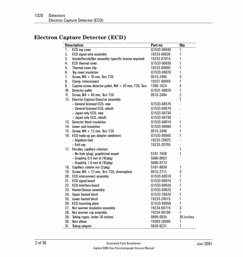
Electron Capture Detector (ECD)
Description Part no. Qty1. ECD top cover G1533-00040 12. ECD signal wire assembly 19233-60635 13. Anode/Ferrule/Nut assembly (specific license required) 19233-67010 14. ECD thermal cover G1533-00030 15. Thermal cover clip 19233-00095 16. Top cover insulation G1533-00020 17. Screw, M4 × 10 mm, Torx T20 0515-2495 38. Clamp, interconnect 19231-00040 19. Captive screw, detector pallet, M4 × 20 mm, T20, Torx 1390-1024 410. Detector pallet G1531-40020 111. Screw, M4 × 45 mm, Torx T20 0515-2484 212. Electron Capture Detector assembly: 1
– General licensed ECD, new G1533-60576 -– General licensed ECD, rebuilt G1533-69576 -– Japan only ECD, new G1533-60730 -– Japan only ECD, rebuilt G1533-69730 -
13. Detector block insulation G1533-00010 114. Lower seal insulation G1533-00080 115. Screw, M4 × 12 mm, Torx T20 0515-2496 116. ECD make-up gas adapter weldment: G1533-80565 1
– Gigabore liner 19233-20625 -– End cap 19233-20755 -
17. Ferrules, capillary columns: 1– No hole (plug), graphitized-vespel 5181-7458 1– Graphite, 0.5 mm id (10/pkg) 5080-8853 -– Graphite, 1.0 mm id (10/pkg) 5080-8773 -
18. Capillary column nut (2/pkg) 5181-8830 119. Screw, M4 × 12 mm, Torx T20, chromeplate 0515-2711 320. ECD interconnect assembly G1533-60510 121. ECD signal board G1533-60010 122. ECD interface board G1533-60020 123. Heater/Sensor assembly G1533-60625 124. Upper heated block G1533-20525 125. Lower heated block 19233-20515 126. ECD mounting plate G1533-00050 127. Nut warmer insulation assembly 19234-60715 328. Nut warmer cup assembly 19234-60700 129. Tubing tygon, (order 30 inches) 0890-0934 30 inches30. Vent elbow 19303-20590 131. Tubing adapter 5020-8231 1
2 of 30 Jun 2001Illustrated Parts Breakdown
Agilent 6890 Gas Chromatograph Service Manual
Detectors 1320Electron Capture Detector (ECD)
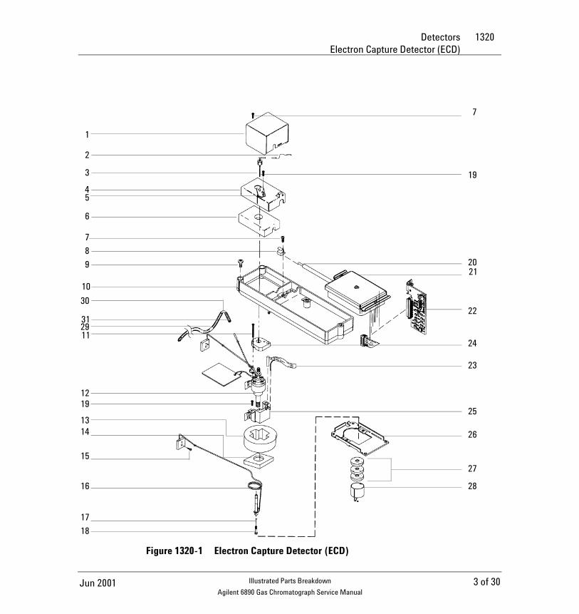
Figure 1320-1 Electron Capture Detector (ECD)
7
19
2021
22
24
23
25
26
27
28
1
2
3
45
6
789
10
30
312911
1219
1314
15
16
1718
3 of 30Jun 2001 Illustrated Parts Breakdown
Agilent 6890 Gas Chromatograph Service Manual
1320 DetectorsElectron Capture Detector manifold assembly
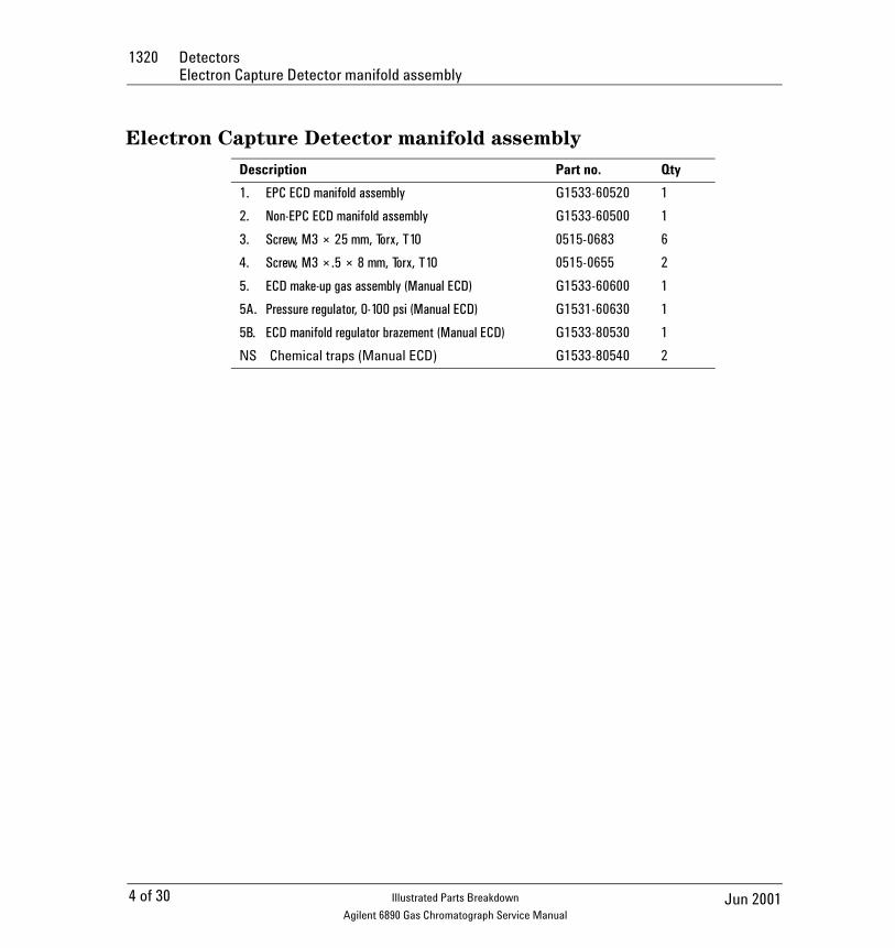
Electron Capture Detector manifold assembly
Description Part no. Qty
1. EPC ECD manifold assembly G1533-60520 1
2. Non-EPC ECD manifold assembly G1533-60500 1
3. Screw, M3 × 25 mm, Torx, T10 0515-0683 6
4. Screw, M3 ×.5 × 8 mm, Torx, T10 0515-0655 2
5. ECD make-up gas assembly (Manual ECD) G1533-60600 1
5A. Pressure regulator, 0-100 psi (Manual ECD) G1531-60630 1
5B. ECD manifold regulator brazement (Manual ECD) G1533-80530 1
NS Chemical traps (Manual ECD) G1533-80540 2
4 of 30 Jun 2001Illustrated Parts Breakdown
Agilent 6890 Gas Chromatograph Service Manual
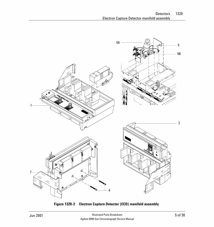
Detectors 1320Electron Capture Detector manifold assembly
Figure 1320-2 Electron Capture Detector (ECD) manifold assembly
2
7
4
1
5
5B
5A
5 of 30Jun 2001 Illustrated Parts Breakdown
Agilent 6890 Gas Chromatograph Service Manual
1320 DetectorsFlame Ionization Detector (FID)
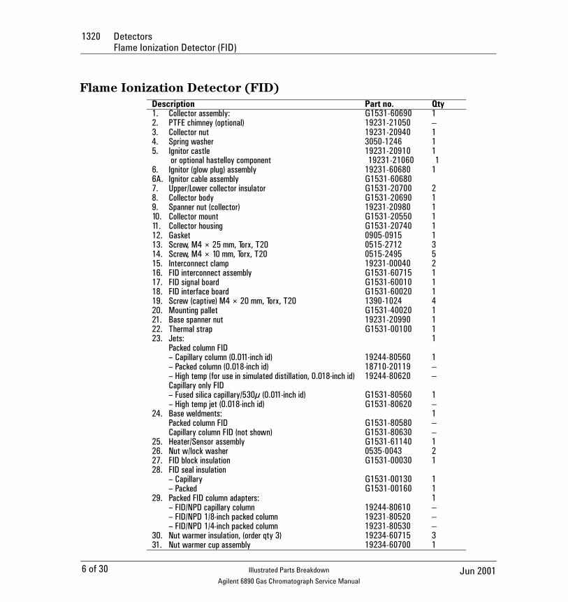
Flame Ionization Detector (FID)Description Part no. Qty1. Collector assembly: G1531-60690 12. PTFE chimney (optional) 19231-21050 – 3. Collector nut 19231-20940 14. Spring washer 3050-1246 15. Ignitor castle
or optional hastelloy component19231-2091019231-21060
11
6. Ignitor (glow plug) assembly 19231-60680 16A. Ignitor cable assembly G1531-606807. Upper/Lower collector insulator G1531-20700 28. Collector body G1531-20690 19. Spanner nut (collector) 19231-20980 110. Collector mount G1531-20550 111. Collector housing G1531-20740 112. Gasket 0905-0915 113. Screw, M4 × 25 mm, Torx, T20 0515-2712 314. Screw, M4 × 10 mm, Torx, T20 0515-2495 515. Interconnect clamp 19231-00040 216. FID interconnect assembly G1531-60715 117. FID signal board G1531-60010 118. FID interface board G1531-60020 119. Screw (captive) M4 × 20 mm, Torx, T20 1390-1024 420. Mounting pallet G1531-40020 121. Base spanner nut 19231-20990 122. Thermal strap G1531-00100 123. Jets: 1
Packed column FID– Capillary column (0.011-inch id) 19244-80560 1– Packed column (0.018-inch id) 18710-20119 – – High temp (for use in simulated distillation, 0.018-inch id) 19244-80620 – Capillary only FID– Fused silica capillary/530µ (0.011-inch id) G1531-80560 1– High temp jet (0.018-inch id) G1531-80620 –
24. Base weldments: 1Packed column FID G1531-80580 – Capillary column FID (not shown) G1531-80630 –
25. Heater/Sensor assembly G1531-61140 126. Nut w/lock washer 0535-0043 227. FID block insulation G1531-00030 128. FID seal insulation
– Capillary G1531-00130 1– Packed G1531-00160 1
29. Packed FID column adapters: 1– FID/NPD capillary column 19244-80610 – – FID/NPD 1/8-inch packed column 19231-80520 – – FID/NPD 1/4-inch packed column 19231-80530 –
30. Nut warmer insulation, (order qty 3) 19234-60715 331. Nut warmer cup assembly 19234-60700 1
6 of 30 Jun 2001Illustrated Parts Breakdown
Agilent 6890 Gas Chromatograph Service Manual
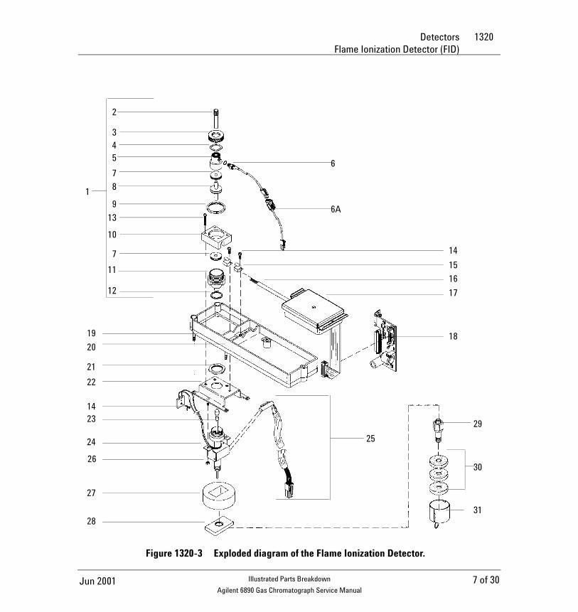
Detectors 1320Flame Ionization Detector (FID)
Figure 1320-3 Exploded diagram of the Flame Ionization Detector.
2
345
67
8
9
13
10
7
11
12
6A
14
15
16
17
18
29
30
31
25
28
27
26
24
2314
22
21
20
1
19
7 of 30Jun 2001 Illustrated Parts Breakdown
Agilent 6890 Gas Chromatograph Service Manual
1320 DetectorsFlame Ionization Detector manifold assemblys
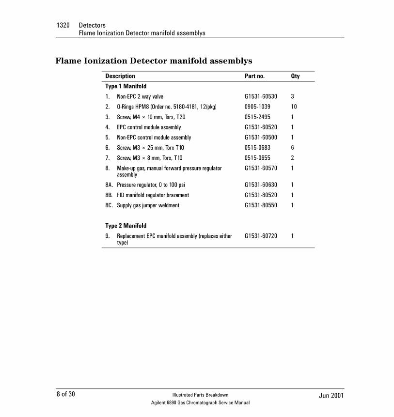
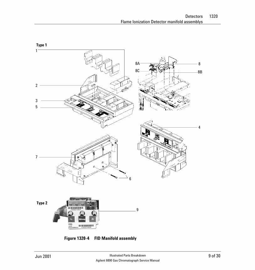
Flame Ionization Detector manifold assemblys
Description Part no. Qty
Type 1 Manifold
1. Non-EPC 2 way valve G1531-60530 3
2. O-Rings HPM8 (Order no. 5180-4181, 12/pkg) 0905-1039 10
3. Screw, M4 × 10 mm, Torx, T20 0515-2495 1
4. EPC control module assembly G1531-60520 1
5. Non-EPC control module assembly G1531-60500 1
6. Screw, M3 × 25 mm, Torx T10 0515-0683 6
7. Screw, M3 × 8 mm, Torx, T10 0515-0655 2
8. Make-up gas, manual forward pressure regulator assembly
G1531-60570 1
8A. Pressure regulator, 0 to 100 psi G1531-60630 1
8B. FID manifold regulator brazement G1531-80520 1
8C. Supply gas jumper weldment G1531-80550 1
Type 2 Manifold
9. Replacement EPC manifold assembly (replaces either type)
G1531-60720 1
8 of 30 Jun 2001Illustrated Parts Breakdown
Agilent 6890 Gas Chromatograph Service Manual
Detectors 1320Flame Ionization Detector manifold assemblys
Figure 1320-4 FID Manifold assembly
8
8B
4
8A
8C
1
2
3
5
7
6
Type 1
Type 2
6
9
9 of 30Jun 2001 Illustrated Parts Breakdown
Agilent 6890 Gas Chromatograph Service Manual
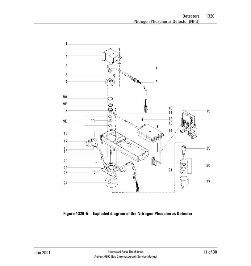
1320 DetectorsNitrogen Phosphorus Detector (NPD)
Nitrogen Phosphorus Detector (NPD) Description Part no. Qty1. Screw, M4 × 10 mm, Torx, T20 0515-2495 12. Hinged cover assembly G1534-80520 13. Screws, M3 ×.5 × 8 mm Torx, T10 0515-0655 34. NPD bead assembly, white G1534-60570 14A. NPD bead assembly, black (optional, not shown) 5183-20075. Screw, M4, Torx, T-20 0515-2495 36. Power cable assembly G1534-60600 17. Lid weldment G1534-80510 18. Collector funnel, standard G1534-20530 18A. Collector funnel, small id (optional, not shown) G1534-206609. NPC ceramic replacement kit, includes: 5182-9722 – 9A. Metal C-ring — 019 0905-2580 19B. Alumina insulator, upper G1534-40020 19C. Alumina insulator, lower G1534-40030 19D. Metal C-ring — 014 0905-1284 210. Screw, M4 × 10 mm 0515-2495 111. J-clamp 1400-0015 112. Screw, M4 × 10 mm 0515-2495 213. NPD interconnect assembly G1534-60610 114. NPD signal board G1534-60010 115. NPD interface board G1534-60020 116. Pallet captive screws 1390-1024 417. O-Rings, HPM8 (Order no. 5180-4181, 12/pkg) 0905-1039 318. Screw, M4 × 10 mm, Torx, T20 0515-2495 119. Mounting pallet G1531-40020 120. Jets: 1
Packed column NPD – Capillary column (0.011-inch id) 19244-80560 1 – Extended jet (optional, not shown) G1534-80590 – Capillary only NPD – Fused silica capillary (0.011-inch id) G1531-80560 1 – Extended jet, capillary only (optional, not shown) G1534-80580 – High temp jet (0.018-inch id) G1531-80620 –
21. Heater/Sensor assembly G1531-61140 122. Base weldment: 1
– Capillary column NPD G1534-80500 – – Packed column NPD G1534-80540 –
23. Lid stop G1534-20590 324. NPD block insulation G1531-00030 125. Column adapters for packed NPD: 1
– Capillary column 19244-80610 – – 1/8-inch packed column 19231-80520 – – 1/4-inch packed column 19231-80530 –
26. Nut warmer insulation (order qty 3) 19234-60715 327. Nut warmer cup 19234-60700 128. Flow measurement adapter (not shown) G1534-60640 –
10 of 30 Jun 2001Illustrated Parts Breakdown
Agilent 6890 Gas Chromatograph Service Manual
Detectors 1320Nitrogen Phosphorus Detector (NPD)
Figure 1320-5 Exploded diagram of the Nitrogen Phosphorus Detector
15
25
26
27
1011
1213
14
21
4
6
1
2
3
5
7
8
9A
9B
9D 9C
16
17
1819
20
22
24
23
11 of 30Jun 2001 Illustrated Parts Breakdown
Agilent 6890 Gas Chromatograph Service Manual
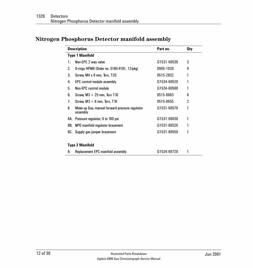
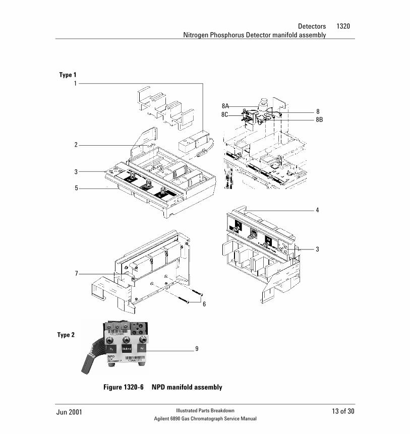
1320 DetectorsNitrogen Phosphorus Detector manifold assembly
Nitrogen Phosphorus Detector manifold assembly
Description Part no. Qty
Type 1 Manifold
1. Non-EPC 2 way valve G1531-60530 3
2. O-rings HPM8 (Order no. 5180-4181, 12/pkg) 0905-1039 9
3. Screw, M4 x 6 mm, Torx, T20 0515-2832 1
4. EPC control module assembly G1534-60520 1
5. Non-EPC control module G1534-60500 1
6. Screw, M3 × 25 mm, Torx T10 0515-0683 6
7. Screw, M3 × 8 mm, Torx, T10 0515-0655 2
8. Make-up Gas, manual forward pressure regulator assembly
G1531-60570 1
8A. Pressure regulator, 0 to 100 psi G1531-60630 1
8B. NPD manifold regulator brazement G1531-80520 1
8C. Supply gas jumper brazement G1531-80550 1
Type 2 Manifold
9. Replacement EPC manifold assembly G1534-60720 1
12 of 30 Jun 2001Illustrated Parts Breakdown
Agilent 6890 Gas Chromatograph Service Manual
Detectors 1320Nitrogen Phosphorus Detector manifold assembly
Figure 1320-6 NPD manifold assembly
Type 1
Type 2
1
2
3
5
7
8A
8B88C
4
3
6
9
13 of 30Jun 2001 Illustrated Parts Breakdown
Agilent 6890 Gas Chromatograph Service Manual
1320 DetectorsThermal Conductivity Detector (TCD)
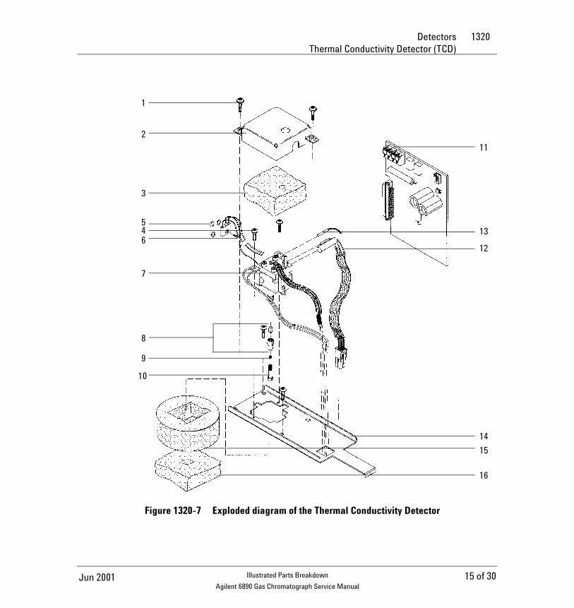
Thermal Conductivity Detector (TCD)
Description Part no. Qty
1. Screw, M4 × 12 mm, captive Torx, T20 0515-2496 2
2. Thermal cover G1532-00040 1
3. Top insulation G1532-00020 1
4. Screw, M4 × 0.7 × 8 mm, chrome plated 0515-2711 2
5. O-rings, HPM8 (Order no. 5180-4181, 12/pkg) 0905-1039 3
6. Screw, M4 × 10 mm, Torx, T20 0515-2495 1
7. TCD assembly G1532-60675 1
8. Column adapters: 1
TCD capillary G1532-80540 –
– 1/8-inch nut (10/pkg) 5180-4103 –
– 1/8-inch vespel ferrule, graphitized (10/pkg) 0100-1332 –
TCD packed, 1/8-inch Tube to 1/4-inch Female (not shown) G1532-20710 –
– 1/8-inch nut (10/pkg) 5180-4103 –
– 1/8-inch vespel ferrule (10/pkg) 0100-1332 –
9. Column ferrules:
– Graphite, 0.5 mm id (10/pkg) 5080-8853 –
– Graphite, 1.0 mm id (10/pkg) 5080-8773 –
10. Column nut (2/pkg) 5181-8830 1
11. TCD signal board* G1532-60015 1
12. Heater/Sensor assembly G1531-61140 1
13. PRT G1531-60660 1
14. TCD mounting pallet G1532-00030 1
15. Bottom insulation G1532-00010 1
16. TCD seal insulation G1532-00080 1
17. TCD vent restrictor kit (not shown) G1532-60700
* For TCDs manufactured before June 1997, order upgrade kit G1532-60540 to replace TCD signal board part no. G1532-60010.
14 of 30 Jun 2001Illustrated Parts Breakdown
Agilent 6890 Gas Chromatograph Service Manual
Detectors 1320Thermal Conductivity Detector (TCD)
Figure 1320-7 Exploded diagram of the Thermal Conductivity Detector
11
12
13
14
1
2
3
546
7
8
9
10
15
16
15 of 30Jun 2001 Illustrated Parts Breakdown
Agilent 6890 Gas Chromatograph Service Manual
1320 DetectorsThermal Conductivity Detector manifold assembly
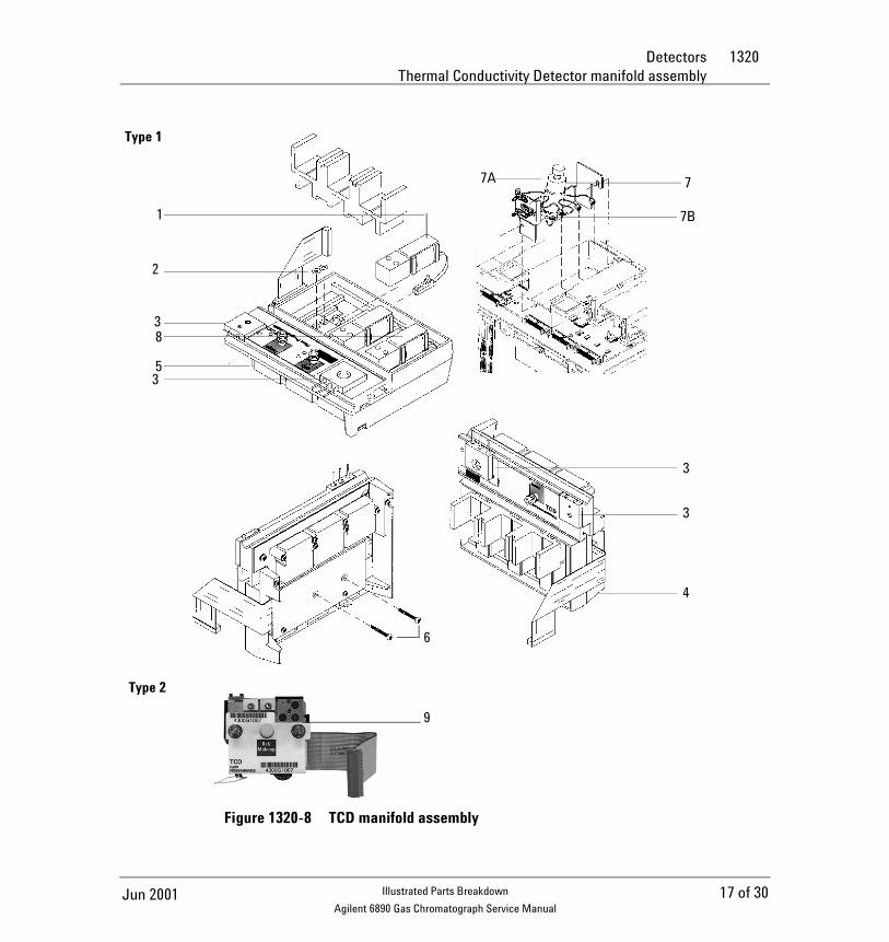
Thermal Conductivity Detector manifold assembly
Description Part no. Qty
Type 1 Manifold
1. Non-EPC detector on-off valve G1531-60530 2
2. O-rings HPM8 Order no. 5180-4181, 12/pkg) 0905-1039 9
3. Screw, M4 × 6 mm, Torx, T20 0515-2832 2
4. EPC control module assembly G1532-60720 1
5. Non-EPC control module assembly G1532-60500 1
6. Screw, M3 × 8 mm, Torx T10 0515-0655 2
7. Make-up gas, manual forward G1532-60530 1
pressure regulator assembly
7A. Pressure regulator, 0 to 100 psi G1531-60630 1
7B. TCD Manifold regulator brazement G1532-80530 1
8. TCD 3-Way switching valve G1532-60570 1
Type 2 Manifold
9. Replacement EPC manifold assembly (replaces either type)
G1532-60720 1
16 of 30 Jun 2001Illustrated Parts Breakdown
Agilent 6890 Gas Chromatograph Service Manual
Detectors 1320Thermal Conductivity Detector manifold assembly
Figure 1320-8 TCD manifold assembly
1
2
3
53
7
7B
7A
3
3
4
6
8
Type 1
Type 2
9
17 of 30Jun 2001 Illustrated Parts Breakdown
Agilent 6890 Gas Chromatograph Service Manual
1320 DetectorsMicrocell Electron Capture Detector (µECD)
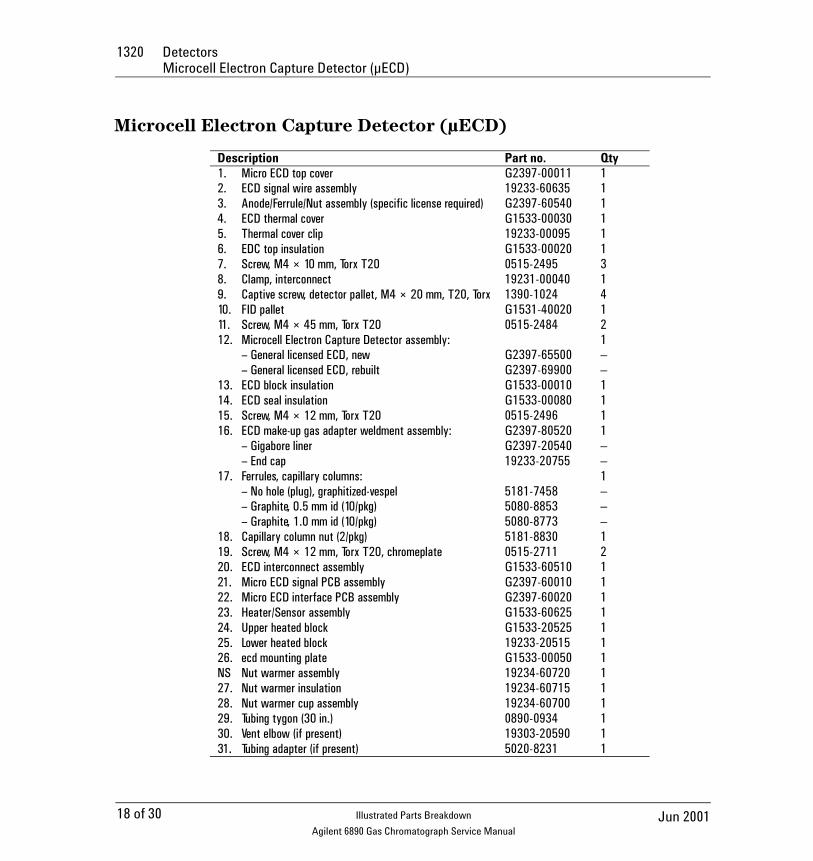
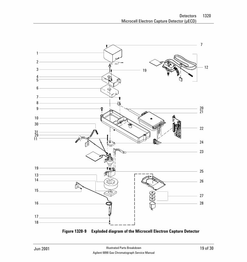
Microcell Electron Capture Detector (µECD)
Description Part no. Qty1. Micro ECD top cover G2397-00011 12. ECD signal wire assembly 19233-60635 13. Anode/Ferrule/Nut assembly (specific license required) G2397-60540 14. ECD thermal cover G1533-00030 15. Thermal cover clip 19233-00095 16. EDC top insulation G1533-00020 17. Screw, M4 × 10 mm, Torx T20 0515-2495 38. Clamp, interconnect 19231-00040 19. Captive screw, detector pallet, M4 × 20 mm, T20, Torx 1390-1024 410. FID pallet G1531-40020 111. Screw, M4 × 45 mm, Torx T20 0515-2484 212. Microcell Electron Capture Detector assembly: 1
– General licensed ECD, new G2397-65500 – – General licensed ECD, rebuilt G2397-69900 –
13. ECD block insulation G1533-00010 114. ECD seal insulation G1533-00080 115. Screw, M4 × 12 mm, Torx T20 0515-2496 116. ECD make-up gas adapter weldment assembly: G2397-80520 1
– Gigabore liner G2397-20540 – – End cap 19233-20755 –
17. Ferrules, capillary columns: 1– No hole (plug), graphitized-vespel 5181-7458 – – Graphite, 0.5 mm id (10/pkg) 5080-8853 – – Graphite, 1.0 mm id (10/pkg) 5080-8773 –
18. Capillary column nut (2/pkg) 5181-8830 119. Screw, M4 × 12 mm, Torx T20, chromeplate 0515-2711 220. ECD interconnect assembly G1533-60510 121. Micro ECD signal PCB assembly G2397-60010 122. Micro ECD interface PCB assembly G2397-60020 123. Heater/Sensor assembly G1533-60625 124. Upper heated block G1533-20525 125. Lower heated block 19233-20515 126. ecd mounting plate G1533-00050 1NS Nut warmer assembly 19234-60720 127. Nut warmer insulation 19234-60715 128. Nut warmer cup assembly 19234-60700 129. Tubing tygon (30 in.) 0890-0934 130. Vent elbow (if present) 19303-20590 131. Tubing adapter (if present) 5020-8231 1
18 of 30 Jun 2001Illustrated Parts Breakdown
Agilent 6890 Gas Chromatograph Service Manual
Detectors 1320Microcell Electron Capture Detector (µECD)
Figure 1320-9 Exploded diagram of the Microcell Electron Capture Detector
7
19
2021
22
24
23
25
26
27
28
1
2
3
45
6
7
8
9
10
30
312911
19
1314
15
16
17
18
12
19 of 30Jun 2001 Illustrated Parts Breakdown
Agilent 6890 Gas Chromatograph Service Manual
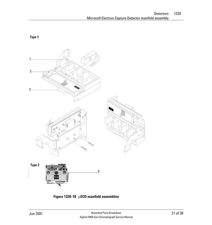
1320 DetectorsMicrocell Electron Capture Detector manifold assembly
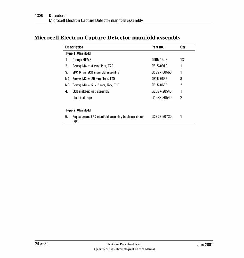
Microcell Electron Capture Detector manifold assembly
Description Part no. Qty
Type 1 Manifold
1. O-rings HPM8 0905-1493 13
2. Screw, M4 × 8 mm, Torx, T20 0515-0910 1
3. EPC Micro ECD manifold assembly G2397-60550 1
NS Screw, M3 × 25 mm, Torx, T10 0515-0683 8
NS Screw, M3 ×.5 × 8 mm, Torx, T10 0515-0655 2
4. ECD make-up gas assembly G2397-20540 1
Chemical traps G1533-80540 2
Type 2 Manifold
5. Replacement EPC manifold assembly (replaces either type)
G2397-60720 1
20 of 30 Jun 2001Illustrated Parts Breakdown
Agilent 6890 Gas Chromatograph Service Manual
Detectors 1320Microcell Electron Capture Detector manifold assembly
Figure 1320-10 µECD manifold assemblies
2
3
Type 1
Type 2
1
5
21 of 30Jun 2001 Illustrated Parts Breakdown
Agilent 6890 Gas Chromatograph Service Manual
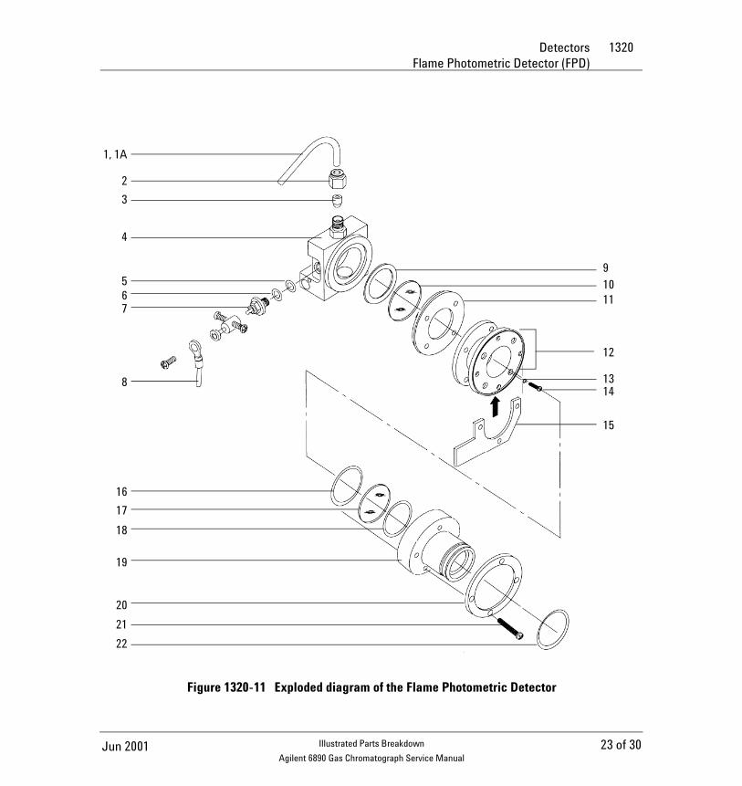
1320 DetectorsFlame Photometric Detector (FPD)
Flame Photometric Detector (FPD)
Description Part no. Qty.
1. Exit tube assembly–A1 19256-20700 1
1A. Exit tube assembly–SST 19256-20705 1
2. Nut, brass, 1/4-inch 0100-0056 1
3. Ferrule, Vespel, 1/4-inch ID (order no. 5080-8774) 0100-1061 1
4. Weldment, block 19256-80560 1
5. O-ring (Kalrez) ignitor 0905-1102 1
6. Spacer, ignitor 19256-20590 1
7. Glow plug 0854-0141 1
8. Ignitor cable assembly G1535-60600 –
9. Gasket, heat shield 19256-80040 1
10. Window, first heat shield 19256-80030 1
11. Disk, heat shield 19256-20580 1
12. Coupling, stainless steel 19256-20550 1
13. Lockwasher (4 required) 2190-0108 4
14. Screw, M3 × 12 (4 required) 0515-0911 4
15. Clamp 19256-00090 1
16. O-ring, silicone, 0.926-inch ID (orange) 0905-0955 1
17. Window, second heat shield 19256-80060 1
18. O-ring, silicone, 1.05-inch ID (orange) 0905-1104 1
19. Flange adapter 19256-20510 1
20. Flange ring 19256-00200 1
21. Screw, M3 × 25 (4 required) 0515-0065 4
22. O-ring, Viton, 1.239-inch ID (brown) 0905-1100 1
22 of 30 Jun 2001Illustrated Parts Breakdown
Agilent 6890 Gas Chromatograph Service Manual
Detectors 1320Flame Photometric Detector (FPD)
Figure 1320-11 Exploded diagram of the Flame Photometric Detector
1, 1A
2
3
4
567
8
16
17
18
19
20
21
22
9
1011
12
1314
15
23 of 30Jun 2001 Illustrated Parts Breakdown
Agilent 6890 Gas Chromatograph Service Manual
1320 DetectorsFlame Photometric Detector jet and transfer tube assemblies
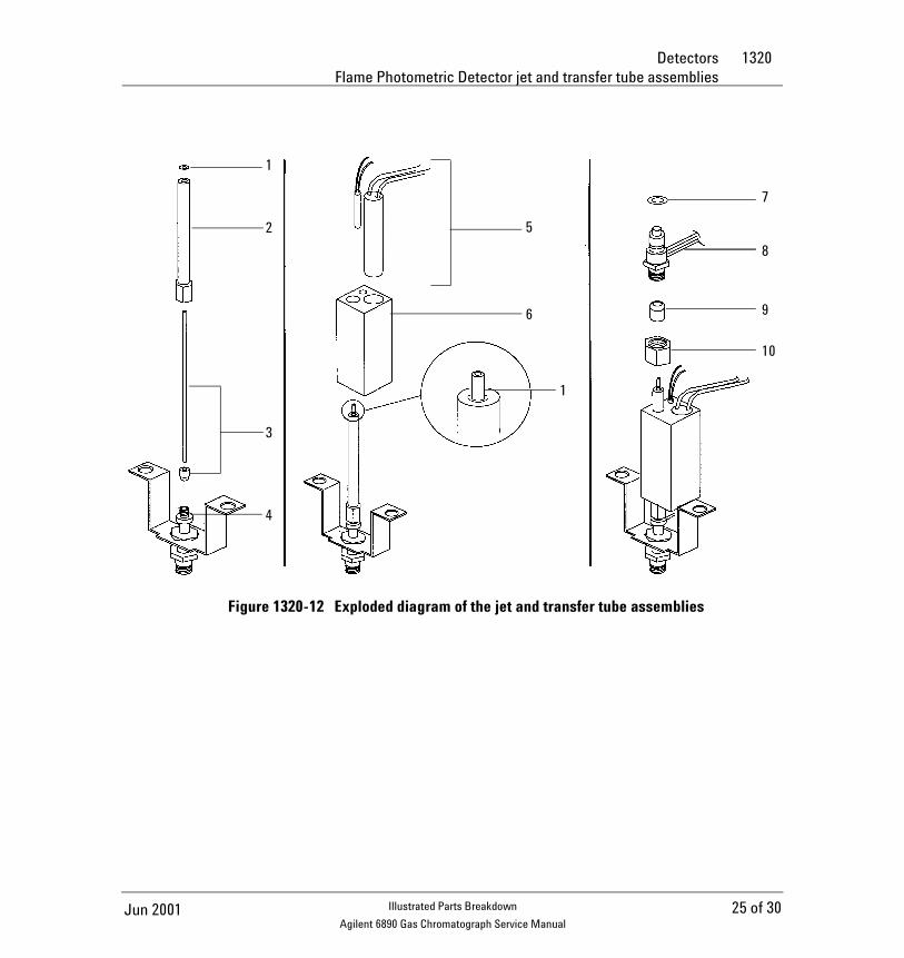
Flame Photometric Detector jet and transfer tube assemblies
Description Part no. Qty.
1. O-ring, Kalrez, transfer tube 0905-1101 1
2. Transfer tube 19256-80550 1
3. Gigabore liner/ferrule assembly 19256-60590 1
4. Base assy, weldment G1535-80510 1
5. Heater/sensor assembly G1535-60620 1
6. Lower heater block 19256-20500 1
7. O-ring (Kalrez), jet cartridge 0905-1103 1
8. Jet cartridge G1535-80500 1
9. Ferrule, Vespel, 1/4-inch ID (Order no. 5080-8774) 0100-1061 1
10. Nut, brass, 1/4-inch 0100-0056 1
24 of 30 Jun 2001Illustrated Parts Breakdown
Agilent 6890 Gas Chromatograph Service Manual
Detectors 1320Flame Photometric Detector jet and transfer tube assemblies
Figure 1320-12 Exploded diagram of the jet and transfer tube assemblies
1
2
3
4
5
6
1
7
8
9
10
25 of 30Jun 2001 Illustrated Parts Breakdown
Agilent 6890 Gas Chromatograph Service Manual
1320 DetectorsFlame Photometric Detector PMT and bracket assemblies
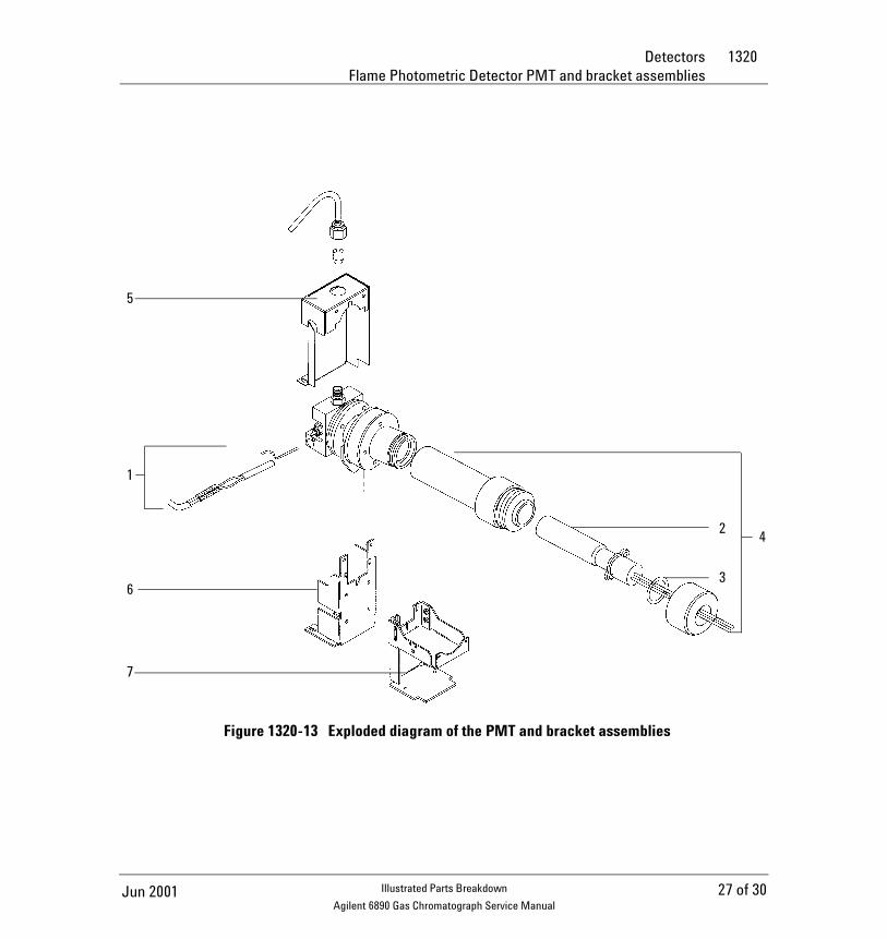
Flame Photometric Detector PMT and bracket assemblies
Description Part no. Qty.
1. Heater/sensor assembly G1535-60610 1
2. Photomultiplier Tube (PMT) G1535-80050 –
3. O-ring 0905-1099 –
4. PM tube and housing assembly 19256-60510 1
5. Main bracket G1535-00010 1
6. Chimney, back G1535-00020 1
7. Chimney, front G1535-00030 1
Filters 1
Sulfur mode (not shown) 19256-80000
Phosphorus mode (not shown) 19256-80010
26 of 30 Jun 2001Illustrated Parts Breakdown
Agilent 6890 Gas Chromatograph Service Manual
Detectors 1320Flame Photometric Detector PMT and bracket assemblies
Figure 1320-13 Exploded diagram of the PMT and bracket assemblies
5
1
6
7
3
42
27 of 30Jun 2001 Illustrated Parts Breakdown
Agilent 6890 Gas Chromatograph Service Manual
1320 DetectorsFlame Photometric Detector covers, manifolds, and electronics
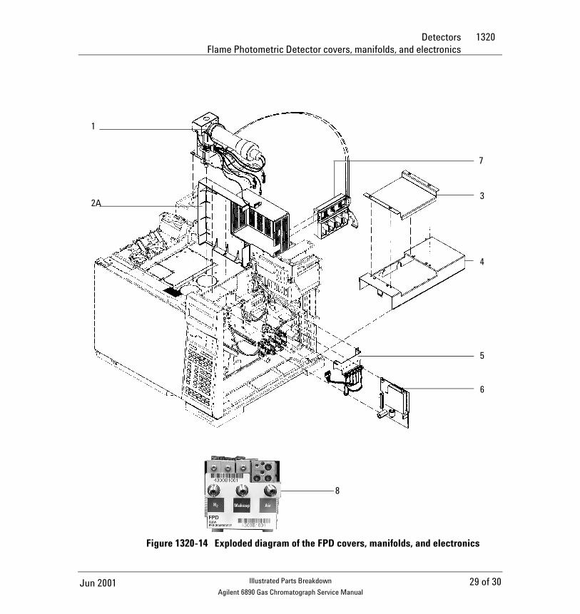
Flame Photometric Detector covers, manifolds, and electronics
Description Part no. Qty.
Covers and electronics
1. Flame photometric detector assembly 1
Single wavelength FPD G1535-60555
Dual wavelength FPD (not shown) G1535-60565
2. Detector top cover, single FPD (not shown) G1535-80550 1
2A. Detector top cover, dual FPDs G1535-80560 1
3. Electronics cover pan G1535-00120 1
4. Electronics top cover G1535-80540 1
Cover assembly (6890 GC) (not shown) G1535-80520 1
5. Actuator solenoid bracket (optional) G1580-00070 –
6. Printed circuit board G1535-60010 1
Spring (not shown) 1460-1160 1
Manifolds
7. Replacement FPD manifold G1535-60720
8. Replacement EPC FPD manifold, Type 2, Kit (replaces either type)
G1535-60720
28 of 30 Jun 2001Illustrated Parts Breakdown
Agilent 6890 Gas Chromatograph Service Manual
Detectors 1320Flame Photometric Detector covers, manifolds, and electronics
Figure 1320-14 Exploded diagram of the FPD covers, manifolds, and electronics
3
4
5
6
7
8
2A
1
29 of 30Jun 2001 Illustrated Parts Breakdown
Agilent 6890 Gas Chromatograph Service Manual
1320 DetectorsAuxiliary flow block
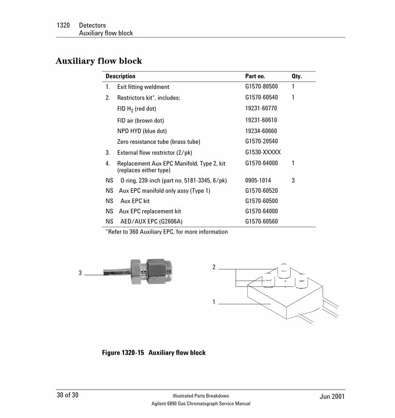
Auxiliary flow block
Figure 1320-15 Auxiliary flow block
Description Part no. Qty.
1. Exit fitting weldment G1570-80500 1
2. Restrictors kit*, includes: G1570-60540 1
FID H2 (red dot) 19231-60770
FID air (brown dot) 19231-60610
NPD HYD (blue dot) 19234-60660
Zero resistance tube (brass tube) G1570-20540
3. External flow restrictor (2/pk) G1530-XXXXX
4. Replacement Aux EPC Manifold, Type 2, kit (replaces either type)
G1570-64000 1
NS O-ring, 239-inch (part no. 5181-3345, 6/pk) 0905-1014 3
NS Aux EPC manifold only assy (Type 1) G1570-60520
NS Aux EPC kit G1570-60500
NS Aux EPC replacement kit G1570-64000
NS AED/AUX EPC (G2606A) G1570-60560
*Refer to 360 Auxiliary EPC, for more information
2
1
3
30 of 30 Jun 2001Illustrated Parts Breakdown
Agilent 6890 Gas Chromatograph Service Manual