12. thermo-hydraulic performance of horizontal ... · thermo-hydraulic performance of horizontal...
TRANSCRIPT

Journal of Engineering and Development, Vol. 18, No.3, May 2014, ISSN 1813- 7822
183
Thermo-Hydraulic Performance of Horizontal Circumferentially Ribbed Double Pipe Heat Exchanger
Asst. Lecturer. Nawras Shareef Sabeeh
Chemical Engineering Department, College of Engineering, Al qadissyah University, Al qadissyah, Iraq
E-mail: [email protected]
Abstract
Heat transfer coefficient and pressure drop for water flow inside circumferential ribbed tubes with different rib dimensions have been determined experimentally. The data of ribbed tubes were compared with that of a plain tube. The experimental test section is a horizontal counter flow concentric tube heat exchanger with circumferentially ribbed inner tube. The ribbed tubes tested in this investigation have the ranges: circumferential depth from 0.5 to 1.5 mm and axial pitch distance from 5 to 15 mm. Water was used as the working fluid, where hot water flows in the inner tube and cold water flows in the annulus. The test runs are done at water flow rates ranging between 0.1 and 1.0 m3/h. The inlet cold and hot water temperatures are between 20 and 30 °C and between 40 and 60 °C, respectively. Comparison of experimental data of circumferentially ribbed tubes with smooth tube have shown that the heat transfer coefficient and pressure drop, quantified by means of Nusselt number and friction factor, are around 1.92 to 5.61 and 1.25 to 3.41 times higher than smooth tube depending on the circumferential geometric parameters and mass velocity of the working fluid. New correlations based on the data gathered during this work for predicting Nusselt number and friction factor for the circumferential ribbed tube heat exchanger have been proposed. The proposed correlations can predict the experimental data with average relative error of ± 6% for Nusselt number and ± 5% for friction factor. Keywords: Circumferentially ribbed tube; double pipe; Heat exchanger.
مضلع بشكل محیطي مزدوج األنبوب أفقيالھیدرولیكي لمبادل حراري - الحراري األداء
حنورس شریف صبی. م.م ، جامعة القادسیة ، كلیة الھندسة ةقسم الھندسة الكیمیاوی
:الخالصة
تم حساب معامل انتقال الحرارة و ھبوط الضغط لتدفق الماء داخل االنابیب المضلعة بشكل محیطي وبأبعاد تضلیع ان مقطع االختبار التجریبي ھو . بیانات االنابیب المضلعة تم مقارنتھا مع تلك الخاصة باألنبوب الناعم. مختلفة تجریبیا
االنابیب . متعاكس الجریان مع انبوب داخلي مضلع بشكل محیطيعبارة عن مبادل حراري افقي متمركز االنبوب و
Journal of Engineering and Development, Vol. 18, No.3, May 2014, ISSN 1813- 7822
184
ملم وبعد محوري من 1,5الى 0,5عمق ضلع محیطي من : اآلتیةالمضلعة التي تم اختبارھا في ھذا البحث لھا المدیات البارد في االنبوب استعمل الماء كمائع تشغیل، حیث یتدفق الماء الحار في االنبوب الداخلي و یتدفق الماء . ملم 15الى 5
درجة حرارة الماء البارد . ساعة/3م 1,0و 0,1ان التجارب المختبریة تم اجراءھا بنسب تدفق ماء تتراوح بین . الحلقيمقارنة البیانات التجریبیة لألنابیب المضلعة بشكل . م، على التوالي° 60الى 40و 30الى 20والساخن تتراوح بین
وضح بان معامل انتقال الحرارة وھبوط الضغط، حددت كمیا بواسطة رقم نسلت ومعامل محیطي مع االنبوب الناعم تمرة اعلى من االنبوب الناعم معتمدة على شكل التضلیع المحیطي 3,41الى 1,25و 5,61الى 1,92االحتكاك، حوالي
انات التي تم جمعھا في ھذا العمل تم اقتراح معادلة ارتباط جدیدة مستندة على البی. والسرعة الكتلویة لمائع التشغیلان معادلة االرتباط المقترحة من . لحساب رقم نسلت ومعامل االحتكاك لمبادل حراري ذو انبوب مضلع بشكل محیطي
.بالنسبة لمعامل االحتكاك% 5±بالنسبة لرقم نسلت و% 6±الممكن ان تحسب البیانات التجریبیة بمعدل خطأ نسبي
Nomenclature
Symbol Meaning Unit A Area for heat transfer m2 C1,C2 Constants - Cp Specific heat of working fluid J/g.K d Hydraulic pipe diameter mm f Fiction factor - F Correction factor for heat transfer rate - h individual heat transfer coefficient W/m2.K k Thermal conductivity of material W/m.K L Length of tube mm ṁ Mass flow rate g/s Nu Nusselt number - p Pitch axial distance mm P Pressure Pa Pr Prendtl number of working fluid - R Thermal resistance K/W Re Reynolds number of working fluid - Q& Average heat transfer rate J/s T Absolute temperature K U Overall heat transfer coefficient W/m2.K V Linear velocity of working fluid m/s x Pitch depth mm ρ Mass density of working fluid g/m3 Subscript Meaning c Cold water f Fouling h Hot water i Inlet conditions l Losses amount LMTD Logarithmic mean temperature difference o Outlet conditions
Journal of Engineering and Development, Vol. 18, No.3, May 2014, ISSN 1813- 7822
185
Introduction
Heat exchangers are equipments that are commonly used to transfer heat between two fluids at different temperatures. They are essential components in engineering systems, ranging from the heavy industries, such as chemical, automotive, power or metallurgy, through the high technique ones such as electronics, to production of every day consumers goods like air conditioning systems, refrigeration, etc. The most popular are those of recuperative type. The fluids are physically separated by heat transfer surface and the heat is transferred from hot to cold agent [1].
Over the last few years, considerable research efforts have been made to improve the heat transfer performance of heat exchangers. The goal of heat transfer improvement is to reduce the size and the cost of heat exchanger equipment, or to increase the heat duty for a given size heat exchanger. The way to improve heat transfer performance is referred to as heat transfer enhancement or augmentation or intensification. Bergles classified the mechanisms of enhancing heat transfer as active or passive methods [2]. Active enhancement is less common because it is costly and complex. It requires the addition of external power to cause a desired flow modification. On the other hand, passive enhancement consists of alteration to the heat transfer surface or incorporation of a device whose presence results in a flow field modification. It is relatively easy to manufacture, cost-effective for many applications. The most common passive heat transfer enhancement techniques nowadays is the use of tubes with ribs because of their superior heat transfer performance [3].
It is commonly understood that the ribs enhances heat transfer but at the same time increases the pressure drop as well. For the laminar flow, several researchers concluded that the heat transfer and pressure drop were not greatly affected by enhanced tubes. While, there is an agreement in researchers conclusions about the heat transfer coefficient and pressure drop increasing for turbulent flow in enhanced tubes [4, 5].
Li et al. explained the heat transfer mechanism by visualizing the flow in helically finned tubes. They indicated that bubbles follow in a parabolic pattern in laminar flow, and this pattern breaks down because of random separation of vortices in the turbulent regime [6]. Fahed et al. showed that the heat transfer and pressure drop in micro fin tubes were just slightly higher than in plain tubes and they recommended that micro fin tubes not be used for laminar flow conditions [5]. Dong et al. examined four helically corrugated tubes in terms of pressure drop and heat transfer coefficient. They concluded that the heat transfer coefficient in turbulent flow regime did not increase not as much as in the friction factor [7]. The work of Jensen and Vlakancic indicated that the micro-fins increase heat transfer ranging from 20 to 220% in turbulent flow region, but there was a penalty due to the increment of friction factor ranging from 40 to 140% [8]. Zdaniuk et al. studied the heat transfer coefficient and the friction factor by using water as a working fluid for eight helically finned tubes and a smooth tube. They evaluated the performance of the predicted correlations with data of other researchers and found average prediction errors between 30% and 40% [9]. Liu and Jensen

Journal of Engineering and Development, Vol. 18, No.3, May 2014, ISSN 1813- 7822
186
numerically modeled periodically fully developed single phase turbulent flow and heat transfer in two helically finned tubes [10].
From the above survey, it could be seen that there is no agreement exists between the works of the different authors because of the limiting experimental data. Therefore, more in-depth studies are necessary. In the present study, the main concern is to provide experimental data in the practical form to quantitatively define the effect of rib depth and rib axil pitch distance on the behavior of the concentric tube heat exchanger with circumferentially ribbed inner tube. Also, this investigation searches to report correlations that account for the effects of the enhancement dimensions on heat transfer coefficient and pressure drop on circumferentially ribbed tube heat exchanger, quantified by Nusselt number and friction factor, respectively. Experimental Work
The heat transfer and pressure drop experimental data used in this study were obtained from the experimental apparatus shown schematically and photographically in Figures (1 and 2) respectively. The test runs were conducted at Al Qadissyah University, college of engineering. The facility mainly consisted of: a concentric tube heat exchanger, temperature controlled water tanks, set of mercury thermometers, U tube manometer, centrifugal water pumps (Begemann, MGH 3500) and variable area flow meters (Liquatec, PMF 0505).
Fig .(1) Schematic diagram of the experimental apparatus.

Journal of Engineering and Development, Vol. 18, No.3, May 2014, ISSN 1813- 7822
187
Fig .(2) Photographic picture of the experimental apparatus.
The test section is a horizontal counter flow circumferentially ribbed tube heat exchanger, which consists of a circular shell and circumferentially ribbed tube. The circumferentially ribbed tube presented an internal circumferential ridging corresponding to an external circumferential grooving. The circumferentially ribs are fabricated by cold rolling a smooth edged wheel on the outer surface of the copper tube as shown photographically with nomenclature to describe the geometry in Figure (3). The inner tube (circumferentially ribbed tube) was made from industrial copper with inner diameter of 14.9 mm while the annulus (smooth tube) was made from galvanized steel with inner diameter of 25.1 mm. The copper tube was soldered into the galvanized steel connectors at both ends. The test section with its effective length of 2000 mm was well insulated by a glass wool with thickness of 5 cm to minimize heat losses to surroundings. The test section and the connections of the piping system are designed such that parts can be changed or repaired easily as possible. Four mercury thermometers were installed at the inlets and outlets of the test section, in which heat was transferred from the hot water flowing inside the test tube to the cold water flowing in the annulus, to monitor the temperatures at the positions. The pressure drop of the test section has been measured by a differential U tube manometer connected to the pressure taps located at the inlet and outlet of the circumferentially ribbed tube. At the entrances of the concentric tube heat exchanger, two rotameters were placed for measuring the flow rates of cold and hot water.
First of all, the apparatus and specially the test section assembly were leaked checked. The inlet hot and cold water temperatures were adjusted to the desired level by using electric

Journal of Engineering and Development, Vol. 18, No.3, May
heaters controlled by thermostats. After that, the hot and cold water are pumped out of the storage tanks and are passed through flow meters, test section and returned to the storage tanks. The flow rate of the hot and cold water were measured by a prewith a range up to 2.5m3/h. The system was allowed to approach the steady state before any data were recorded. The steady state condition was reached when the temperatures and flow rates at all measuring points were no longer fluctuating. Fig .(3) Photographic picture of the fabrication for the circumferentially ribbed
The uncertainties of the measurements of the pressure difference, flow rate and temperature were within ±0.07kPa, ±0.005mthe low thermal conductivity of soft solder and connectors, the heat leak through the end points was estimated to be less than 2% of the total heat transferred.
Mathematical Work The performance of enhanced tubes were determined in terms of heat transfer
enhancement and pressure drop penalty, quantified by means of the Nusselt number and friction factor values, respectively. The calculations were presented onapproach basis since it is effective for correlating enhanced tubes relations
According to the experimental results, the heat supplied by the hot water is found to be 5 to 10% higher than the heat absorbed by the cold water a
g and Development, Vol. 18, No.3, May 2014, ISSN 1813
188
heaters controlled by thermostats. After that, the hot and cold water are pumped out of the storage tanks and are passed through flow meters, test section and returned to the storage
te of the hot and cold water were measured by a pre-calibrated rotameters /h. The system was allowed to approach the steady state before any
data were recorded. The steady state condition was reached when the temperatures and flow ates at all measuring points were no longer fluctuating.
Photographic picture of the fabrication for the circumferentially ribbed tubes.
The uncertainties of the measurements of the pressure difference, flow rate and temperature were within ±0.07kPa, ±0.005m3/h and 0.5K, respectively. Furthermore, due to
thermal conductivity of soft solder and connectors, the heat leak through the end points was estimated to be less than 2% of the total heat transferred.
The performance of enhanced tubes were determined in terms of heat transfer enhancement and pressure drop penalty, quantified by means of the Nusselt number and friction factor values, respectively. The calculations were presented on hydraulic diameter approach basis since it is effective for correlating enhanced tubes relations [11].
According to the experimental results, the heat supplied by the hot water is found to be 5 to 10% higher than the heat absorbed by the cold water at thermal equilibrium due to
2014, ISSN 1813- 7822
heaters controlled by thermostats. After that, the hot and cold water are pumped out of the storage tanks and are passed through flow meters, test section and returned to the storage
calibrated rotameters /h. The system was allowed to approach the steady state before any
data were recorded. The steady state condition was reached when the temperatures and flow
Photographic picture of the fabrication for the circumferentially ribbed
The uncertainties of the measurements of the pressure difference, flow rate and y. Furthermore, due to
thermal conductivity of soft solder and connectors, the heat leak through the end
The performance of enhanced tubes were determined in terms of heat transfer enhancement and pressure drop penalty, quantified by means of the Nusselt number and
hydraulic diameter
According to the experimental results, the heat supplied by the hot water is found to be 5 t thermal equilibrium due to

Journal of Engineering and Development, Vol. 18, No.3, May 2014, ISSN 1813- 7822
189
convection heat loss from the test section to surroundings. This heat loss through the heat exchanger insulation analytically obtained from water and ambient temperatures. Furthermore, 2% of the total heat transferred was added due to heat leak through the end points of the heat exchanger. So, the average heat transfer rate in the test section used for further analysis is determined from the hot water side and cold water side as indicated in equation (1) [12]:
( ){ } ( ){ }[ ]licocccohihhh QTTCpmTTCpmQ &&&& +−+−= ,,,,21 .......(1)
For fluids flows in a concentric tube heat exchanger, the overall heat transfer coefficient can be determined from the equation (2) with a correction factor, F equal to 1 for this case. Furthermore, the bulk fluid temperatures were assumed to increase linearly from the inlet to the outlet.
( )FTUAQ LMTDi∆=& .......(2)
In the experiments, the tube wall temperature was not measured directly. Therefore, the inside heat transfer coefficient required a more complex approach because information about heat transfer in the annulus had to be obtained first. The heat transfer in the double pipe, counter flow heat exchanger is governed by the total thermal resistance equation as indicated in equation (3). The axial conduction was assumed negligible since Re·Pr > 4200 in all cases, but peripheral and radial conduction of heat transfer in the tube wall were included [12].
( )f
oo
io
iioioi
RAhkL
ddAhAU
+++=1
2ln11
π .......(3)
The resistance due to fouling, Rf was neglected in further analysis since new tubes were always used through the work. The inside heat transfer coefficient was obtained by means of Wilson method [13]. The theory states that; if the flow of the heating fluid was modified, then the change in the overall thermal resistance would be mainly due to the variation of the inside heat transfer coefficient, while the remaining thermal resistances can assumed constant. Therefore, the thermal resistances outside of the tube and the tube wall could be represented as shown in equation (4):
( )1
12
ln CAhkL
dd
oo
io =+π
.......(4)

Journal of Engineering and Development, Vol. 18, No.3, May 2014, ISSN 1813- 7822
190
Furthermore, the inside heat transfer coefficient is assumed to be represented by Dittus – Boelter equation of the form shown in equation (5) [9]:
3.02 PrRe i
ni
i
ii Ckdh
= .......(5)
The 0.3 exponential coefficient was chosen because the water in the pipe was being cooled. Upon combining Equations (3), (4) and (5), the overall heat transfer coefficient turns out to be a linear function of 1/Ren with intercept and slope equal to C1 and di/C2AikiPr0.3 respectively, as illustrated in equation (6):
niiii
i
oioi kACdC
AU Re1
Pr1
3.02
1 += .......(6)
The friction factor for the tube with circumferentially ribs can be calculated from the experimental results of pressure drop inside tubes by Darcy - Weisbach equation of the form shown in equation (7) [14]:
LVPd
f i2
2ρ
∆= .......(7)
Results and discussion To check that the experimental setup can be used for single phase heat transfer and pressure drop data of circumferentially ribbed tubes, experiments for plain tube were conducted first. Plain tube results have been compared with Dittus-Boelter and Blasius equations and shown in Figure (4). The figure implies that the maximum percent difference between the data and the correlations were below 6% for Nusselt numbers and 8% for friction factors. The figure shows that the tube side Nusselt numbers considerably increases with increasing Reynolds number. Turbulent flow in a tube exhibits a low velocity flow region immediately adjacent to the wall, known as the laminar sub layer, with velocity approaching zero at the wall. Most of the thermal resistance occurs in this low velocity region. The improvement of heat transfer with increasing Reynolds number is responsible by a decrease of thermal boundary layer thickness due to the promoted turbulent intensity. But, in the same time, this turbulence augmentation has a great effect on pressure drop due to its action on wall shear stress. Therefore, the friction factors considerably decrease with increasing Reynolds number.

Journal of Engineering and Development, Vol. 18, No.3, May 2014, ISSN 1813- 7822
191
Figure (5 and 6) indicate that for ribbed tubes, the Nusselt number increase and friction factor decrease with increasing Reynolds number in a manner similar to that for plain tube but with higher ranges of values. This is because that the presence of circumferentially ribs possibly promotes the dispersion and random movement of the particles, resulting in a better mixing between the core fluid and the tube wall one. In addition, limiting the growth of fluid boundary layer close to the heat transfer surface because periodic disruption of the layer due to repeated changes in the geometry-existence of cross flow. Furthermore, circumferentially ribbed tube provides large contact surfaces between fluid and wall and thus heat transfer area. But the presence of circumferentially ribs causes more inner surface area which causes more wall shear stress, so more drag forces exerted. Therefore tubes with circumferentially ribs show higher friction factors. Furthermore, this increase in drag forces is of special form, since it represents the area of stronger collision of fluid streams directed by ribs surface due to flow blockage and area reduction. By comparing Figures (5 and 6), it could be concluded that the increasing in Nusselt numbers due to decreasing in pitch distance much higher than increasing in pitch depth. Furthermore, the increasing in friction factors due to decreasing in pitch distance much lower than increasing in pitch depth. Therefore, it could be concluded that the decreasing in pitch distance is more efficient than increasing in pitch depth for heat transfer as positive effect and pressure drop as negative effect in circumferentially ribbed tubes.
Fig.(4.a) , Nusselt number versus Reynolds number for plain tube
Fig.( 4.b), Friction factor versus Reynolds number for plain tube

Journal of Engineering and Development, Vol. 18, No.3, May 2014, ISSN 1813- 7822
192
Fig .(6.b) Friction factor versus Reynolds number for circumferentially ribbed tubes with pitch distance equal
to 10 mm.
Fig .(6.a) Nusselt number versus Reynolds number for
circumferentially ribbed tubes with pitch distance equal to 10 mm.
Fig.( 5.a) Nusselt number versus Reynolds number for circumferentially
ribbed tubes with pitch depth equal to 1 mm.
Fig.( 5.b), Friction factor versus Reynolds number for circumferentially
ribbed tubes with pitch depth equal to 1 mm

Journal of Engineering and Development, Vol. 18, No.3, May 2014, ISSN 1813- 7822
193
Based on the present experimental data, the tube side heat transfer coefficient and pressure drop are proposed in terms of Nusselt number and friction factor and correlated by power-law approach. The correlations were yielded by utilizing least-squares regression approach and they are of the forms shown in equations (8 and 9):
85.041.032.074.0 PrRe692.0
−−
=
dp
dxNu .......(8)
37.089.0
24.0Re618.1−
−
=
dp
dxf .......(9)
Comparisons between the Nusselt numbers and friction factors obtained from the present experiments with those calculated from the proposed correlations are shown in Figure 7. It can be clearly noted from the figure that more than 95% of the values obtained from the correlations are consistent with the experimental data and lie within ± 6% for Nusselt numbers and ± 5% for friction factors.
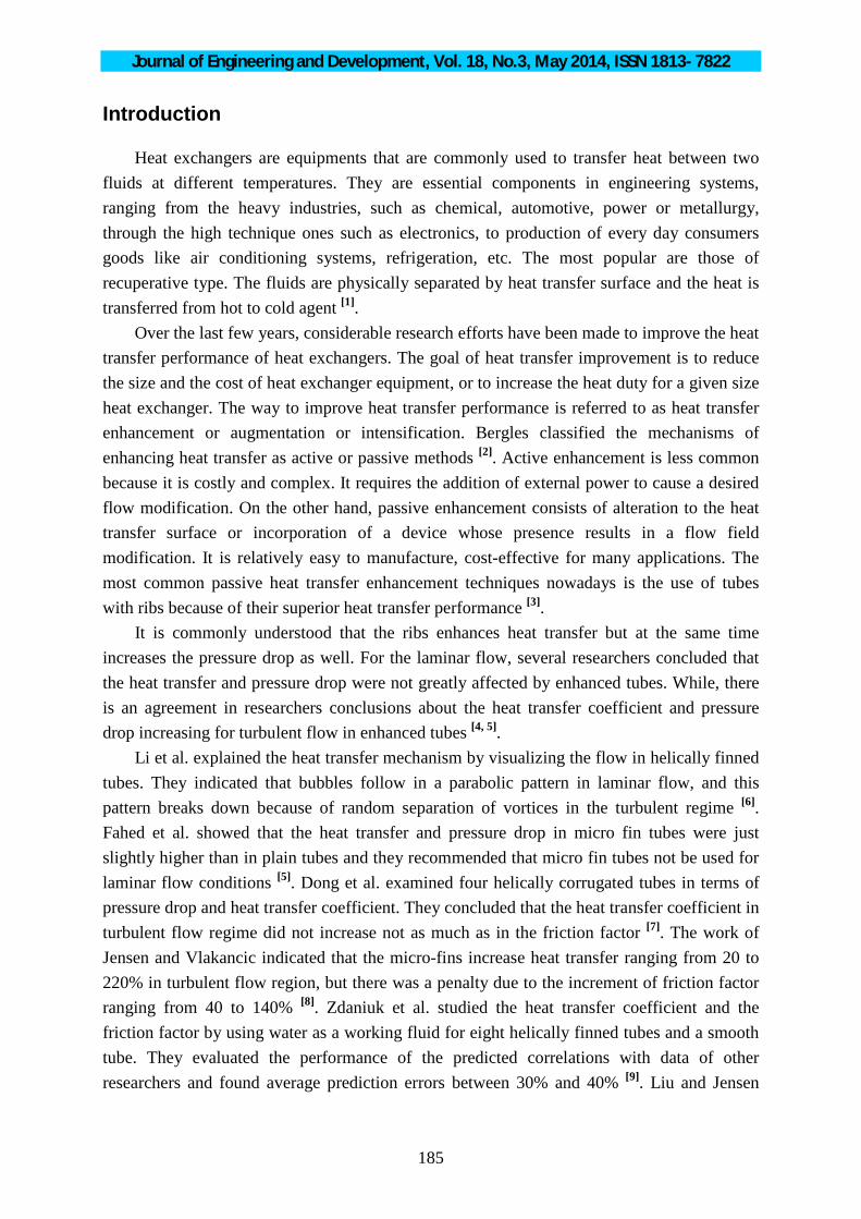
Figures (8 and 9) show Nusselt numbers and friction factors ratios (the ratio represents the value for the circumferentially ribbed tubes to that for smooth tube) as a function of Reynolds number.
Fig .( 7.b) Experimental versus predicted friction factor with error
indications for all data points obtained in this work
Fig. (7.a) Experimental versus predicted Nusselt number with error
indications for all data points obtained in this work
Journal of Engineering and Development, Vol. 18, No.3, May 2014, ISSN 1813- 7822
194
Fig .(8.b) Friction factor ratio versus Reynolds number for
circumferentially ribbed tubes with pitch depth equal to 1 mm
Fig .(8.a) Nusselt number ratio versus Reynolds number for
circumferentially ribbed tubes with pitch depth equal to 1 mm
Fig .(9.b) Friction factor ratio versus Reynolds number for
circumferentially ribbed tubes with pitch distance equal to 10mm.
Fig .(9.a) Nusselt number ratio versus Reynolds number for
circumferentially ribbed tubes with pitch distance equal to 10mm.
Journal of Engineering and Development, Vol. 18, No.3, May 2014, ISSN 1813- 7822
195
The figures show that the utilization of circumferentially ribbed tube, Nusselt numbers increase from 92 to 461% and friction factor increase from 25 to 241% compared to those obtained in smooth tube depending on ribs geometry and operating conditions. Therefore, it can be stated that for the range investigated, the benefits from the heat transfer improvement as a positive effect over that from the increase of friction loss as a negative effect. This outcome becomes obvious at low Reynolds numbers. Conclusions • For circumferentially ribbed tubes, the Nusselt number increase and friction factor decrease with increasing Reynolds number in a manner similar to that for smooth tube but with higher ranges of values • The decreasing in pitch distance is more efficient than increasing in pitch depth for heat transfer as positive effect and pressure drop as negative effect in circumferentially ribbed tubes. • New correlations of Nusselt number and friction factor for circumferentially ribbed tubes have been proposed. The good agreement between experimental and analytical results validates the capacity of the proposed expressions to predict the behavior of the circumferentially ribbed tubes for practical applications. • For circumferentially ribbed tube, Nusselt numbers increase from 92 to 461% and friction factor increase from 25 to 241% compared to those obtained in smooth tube depending on ribs geometry and operating conditions.
Acknowledgement The author would like to express her appreciation to the College of Engineering/ Al qadissyah University for providing full support for this work. The author wishes to acknowledge the help of Mr. Ganim Daham Zamat.
References 1. Dalkilic A.S. and Wongwises S., Intensive literature review of condensation inside smooth and enhanced tubes, Int. J. Heat & Mass Trans., 52, 3409 (2009). 2. Bergles E.A., The implications and challenges of enhanced heat transfer for the chemical process industries, Chem. Eng. Res. & Des., 79 (4), 437 (2001). 3. Ravigururajan T.S. and Rabas T.J., Turbulent flow in integrally enhanced tubes, Part I: Comprehensive review and data base development, Heat Trans. Eng., 17 (2), 19 (1996).
Journal of Engineering and Development, Vol. 18, No.3, May 2014, ISSN 1813- 7822
196
4. Esen E.B., Obot N.T. and Rabas T.J., Enhancement: Part I. Heat transfer and pressure drop results for air flow through passages with spirally-shaped roughness, J. En. Trans., 1 (2), 145 (1994). 5. Fahed S., Chamra L.M. and Chakroun W., Pressura drop and heat transfer comparison for both micro fin tube and twisted tape inserts in laminar flow, Exp. Therm. & Fluid Sci., 18, 232 (1999). 6. Li H.M., Ye K.S., Tan Y.K. and Dong S.J., Investigation on tube-side flow visualization, friction factor and heat transfer characteristics of helical-ridging tubes, Proceedings of the 7th Int. Heat Trans. Conf., 3, 75 (1982). 7. Dong Y., Huixiung L. and Tingkuan C., Pressure drop, heat transfer and performance of single phase turbulent flow in spirally corrugated tubes, Exp. Therm. & Fluid Sci., 32, 761 (2008). 8. Jensen M.K. and Vlakancic A., Technical note-experimental investigation of turbulent heat transfer and fluid flow in internally finned tubes, Int. J. Heat & Mass Trans., 42, 1343 (1999). 9. Zdaniuk G.J., Luck R. and Chamra L.M., Linear correlation of heat transfer and friction in helically-finned tubes using five simple groups of parameters, Int. J. Heat & Mass Trans., 51, 3548 (2008). 10. Liu X. and Jensen M.K., Numerical investigation of turbulent flow and heat transfer in internally finned tubes, J. En. Heat Trans., 6, 105 (1999). 11. Huq A., Huq A.M. and Rahman M.M., Experimental mesurements of heat transfer in an internally finned tube, Int. Comm. Heat & Mass Trans., 25 (5), 619 (1998). 12. Wongcharee K. and Eiamsa S., Heat transfer enhancement by using CuO/water nanofluid in corrugated tube equipped with twisted tape, Int. Comm. Heat & Mass Trans., 39, 251 (2012). 13. Hasim F., Yoshida M. and Miyashita H., Compound heat transfer enhancement by a combination of ribbed tubes with coil inserts, J. Chem. Eng. Japan, 36, 647 (2003). 14. Ağra Ö., Demir H., Atayilmaz Ş.Ö., Kantaş F. and Dalkiliç A.S., Numerical investigation of heat transfer and pressure drop in enhanced tubes, Int. Comm. Heat & Mass Trans., 38, 1384 (2011).