1100 series magnetic level indicators - sor inc. · 1100 series magnetic level indicators are...
TRANSCRIPT
SORInc.com | 913-888-2630 | Registered Quality System to ISO 9001 1Form 1596 (05.18) ©SOR Inc.
1100 SeriesMagnetic
Level Indicators
with
indicator
VIEW Matters
200ºviewing angle
The
200ºviewing angle
Registered Quality System to ISO 9001 | 913-888-2630 | SORInc.com2 Form 1596 (05.18) ©SOR Inc.
Features and Benefits _ _ _ _ _ _ _ _ 3
Complete Level Solution _ _ _ _ _ _ _ 4
Principals of Operation _ _ _ _ _ _ _ _ 5
Industries and Applications _ _ _ _ _ 5
Design Attributes _ _ _ _ _ _ _ _ _ _ 6
Specifications _ _ _ _ _ _ _ _ _ _ _ _ 7
How to Order _ _ _ _ _ _ _ _ _ _ _ _ _ 8
Auxiliary Products _ _ _ _ _ _ _ _ _ _ 12
Application Data Sheet _ _ _ _ _ _ _ 13
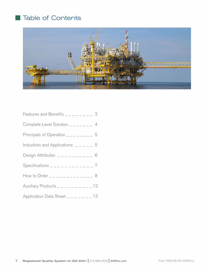
Table of Contents
SORInc.com | 913-888-2630 | Registered Quality System to ISO 9001 3Form 1596 (05.18) ©SOR Inc.
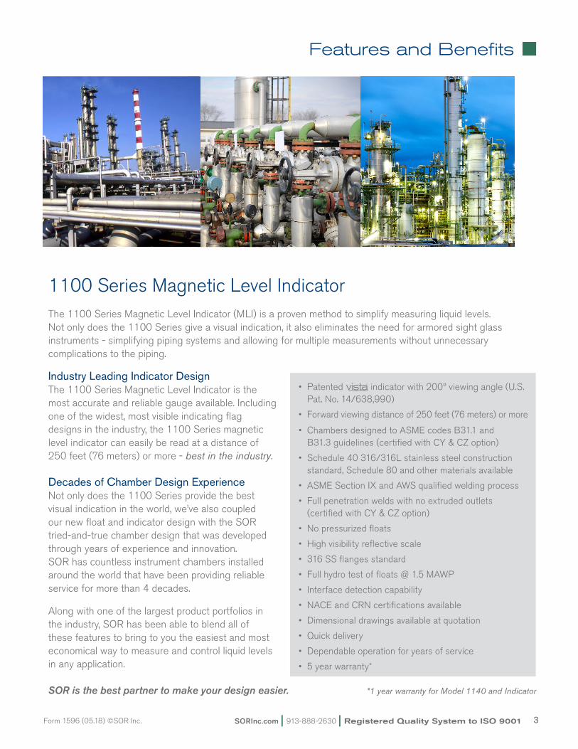
1100 Series Magnetic Level Indicator The 1100 Series Magnetic Level Indicator (MLI) is a proven method to simplify measuring liquid levels. Not only does the 1100 Series give a visual indication, it also eliminates the need for armored sight glass instruments - simplifying piping systems and allowing for multiple measurements without unnecessary complications to the piping.
Industry Leading Indicator DesignThe 1100 Series Magnetic Level Indicator is the most accurate and reliable gauge available. Including one of the widest, most visible indicating flag designs in the industry, the 1100 Series magnetic level indicator can easily be read at a distance of 250 feet (76 meters) or more - best in the industry.
Decades of Chamber Design ExperienceNot only does the 1100 Series provide the best visual indication in the world, we’ve also coupled our new float and indicator design with the SOR tried-and-true chamber design that was developedthrough years of experience and innovation. SOR has countless instrument chambers installed around the world that have been providing reliable service for more than 4 decades.
Along with one of the largest product portfolios in the industry, SOR has been able to blend all of these features to bring to you the easiest and most economical way to measure and control liquid levels in any application.
SOR is the best partner to make your design easier.
Features and Benefits
• Patented indicator with 200º viewing angle (U.S. Pat. No. 14/638,990)
• Forward viewing distance of 250 feet (76 meters) or more
• Chambers designed to ASME codes B31.1 and B31.3 guidelines (certified with CY & CZ option)
• Schedule 40 316/316L stainless steel construction standard, Schedule 80 and other materials available
• ASME Section IX and AWS qualified welding process
• Full penetration welds with no extruded outlets (certified with CY & CZ option)
• No pressurized floats
• High visibility reflective scale
• 316 SS flanges standard
• Full hydro test of floats @ 1.5 MAWP
• Interface detection capability
• NACE and CRN certifications available
• Dimensional drawings available at quotation
• Quick delivery
• Dependable operation for years of service
• 5 year warranty*
*1 year warranty for Model 1140 and Indicator
Registered Quality System to ISO 9001 | 913-888-2630 | SORInc.com4 Form 1596 (05.18) ©SOR Inc.
With SOR, the solution is available from us – one source. You don’t have to worry about
everything fitting and operating together. All you have to do is select a magnetic level indicator,
point level switch, magnetostrictive level transmitter or a guided wave radar that are designed to
work seamlessly together to provide one of the most reliable solutions in the industry.
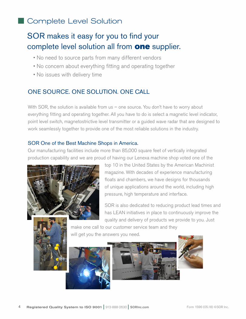
SOR One of the Best Machine Shops in America.Our manufacturing facilities include more than 85,000 square feet of vertically integrated
production capability and we are proud of having our Lenexa machine shop voted one of the
top 10 in the United States by the American Machinist
magazine. With decades of experience manufacturing
floats and chambers, we have designs for thousands
of unique applications around the world, including high
pressure, high temperature and interface.
SOR is also dedicated to reducing product lead times and
has LEAN initiatives in place to continuously improve the
quality and delivery of products we provide to you. Just
make one call to our customer service team and they
will get you the answers you need.
Complete Level Solution
SOR makes it easy for you to find your complete level solution all from one supplier. •Noneedtosourcepartsfrommanydifferentvendors
•Noconcernabouteverythingfittingandoperatingtogether
•Noissueswithdeliverytime
ONE SOURCE. ONE SOLUTION. ONE CALL
SORInc.com | 913-888-2630 | Registered Quality System to ISO 9001 5Form 1596 (05.18) ©SOR Inc.
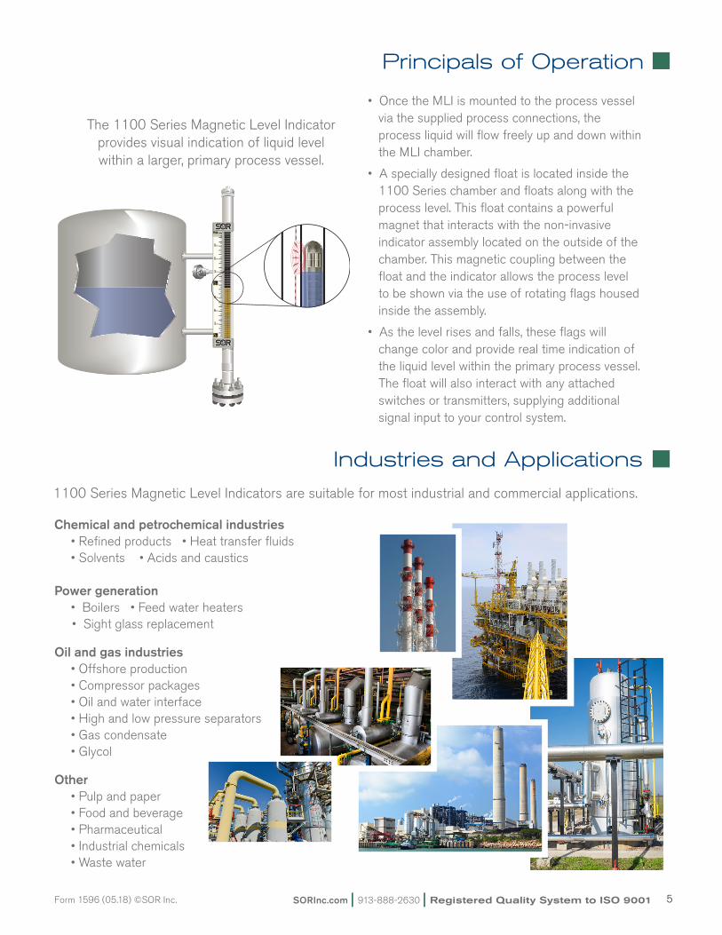
•OncetheMLIismountedtotheprocessvesselvia the supplied process connections, the process liquid will flow freely up and down within the MLI chamber.
•Aspeciallydesignedfloatislocatedinsidethe1100 Series chamber and floats along with the process level. This float contains a powerful magnet that interacts with the non-invasive indicator assembly located on the outside of the chamber. This magnetic coupling between the float and the indicator allows the process level to be shown via the use of rotating flags housed inside the assembly.
•Asthelevelrisesandfalls,theseflagswillchange color and provide real time indication of the liquid level within the primary process vessel. The float will also interact with any attached switches or transmitters, supplying additional signal input to your control system.
Principals of Operation
Industries and Applications
Chemical and petrochemical industries •Refinedproducts•Heattransferfluids •Solvents•Acidsandcaustics Power generation •Boilers•Feedwaterheaters•Sightglassreplacement
Oil and gas industries •Offshoreproduction •Compressorpackages •Oilandwaterinterface •Highandlowpressureseparators •Gascondensate •Glycol
Other •Pulpandpaper •Foodandbeverage •Pharmaceutical •Industrialchemicals •Wastewater
1100 Series Magnetic Level Indicators are suitable for most industrial and commercial applications.
The 1100 Series Magnetic Level Indicator provides visual indication of liquid level within a larger, primary process vessel.
Registered Quality System to ISO 9001 | 913-888-2630 | SORInc.com6 Form 1596 (05.18) ©SOR Inc.
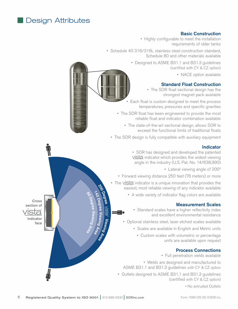
200 Degree vis
ta™ View
ing Area
Crosssection of
indicatorface
140 Degree View
ing Area
90 Degree View
ing Area
Basic Construction•Highlyconfigurabletomeettheinstallation
requirements of older tanks
•Schedule40316/316Lstainlesssteelconstructionstandard,Schedule 80 and other materials available
•DesignedtoASMEB31.1andB31.3guidelines(certified with CY & CZ option)
•NACEoptionavailable
Standard Float Construction•TheSORfloatsectionaldesignhasthe
strongest magnet pack available
•Eachfloatiscustomdesignedtomeettheprocesstemperatures, pressures and specific gravities
•TheSORfloathasbeenengineeredtoprovidethemostreliable float and indicator combination available
•Thestate-of-the-artsectionaldesign,allowsSORtoexceed the functional limits of traditional floats
•TheSORdesignisfullycompatiblewithauxiliaryequipment
Indicator•SORhasdesignedanddevelopedthepatented
indicator which provides the widest viewing angle in the industry (U.S. Pat. No. 14/638,990)
•Lateralviewingangleof200º
•Forwardviewingdistance250feet(76meters)ormore
•The indicator is a unique innovation that provides the easiest, most reliable viewing of any indicator available
•Awidevarietyofindicatorflagcolorsareavailable
Measurement Scales•Standardscaleshaveahigherreflectivityindex
and excellent environmental resistance
•Optionalstainlesssteel,laseretchedscalesavailable
•ScalesareavailableinEnglishandMetricunits
•Customscaleswithvolumetricorpercentageunits are available upon request
Process Connections •Fullpenetrationweldsavailable
•WeldsaredesignedandmanufacturedtoASME B31.1 and B31.3 guidelines with CY & CZ option
•OutletsdesignedtoASMEB31.1andB31.3guidelines(certified with CY & CZ option)
•NoextrudedOutlets
Design Attributes
SORInc.com | 913-888-2630 | Registered Quality System to ISO 9001 7Form 1596 (05.18) ©SOR Inc.
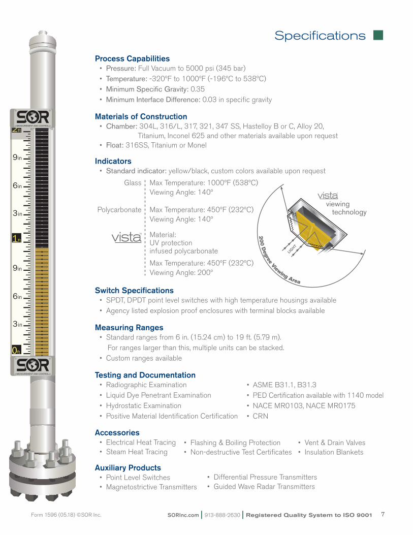
Process Capabilities •Pressure: Full Vacuum to 5000 psi (345 bar) •Temperature: -320ºF to 1000ºF (-196ºC to 538ºC) •Minimum Specific Gravity: 0.35 •Minimum Interface Difference: 0.03 in specific gravity
Materials of Construction•Chamber: 304L, 316/L, 317, 321, 347 SS, Hastelloy B or C, Alloy 20, Titanium, Inconel 625 and other materials available upon request•Float: 316SS, Titanium or Monel
Indicators•Standard indicator: yellow/black, custom colors available upon request
Glass MaxTemperature:1000ºF(538ºC) ViewingAngle:140º
Polycarbonate MaxTemperature:450ºF(232ºC) ViewingAngle:140º
Material: UV protection infused polycarbonate
MaxTemperature:450ºF(232ºC) ViewingAngle:200º
Switch Specifications•SPDT,DPDTpointlevelswitcheswithhightemperaturehousingsavailable•Agencylistedexplosionproofenclosureswithterminalblocksavailable
Measuring Ranges •Standardrangesfrom6in.(15.24cm)to19ft.(5.79m). For ranges larger than this, multiple units can be stacked. •Customrangesavailable
Testing and Documentation•RadiographicExamination•LiquidDyePenetrantExamination•HydrostaticExamination•PositiveMaterialIdentificationCertification
Accessories•ElectricalHeatTracing•SteamHeatTracing
Auxiliary Products •PointLevelSwitches•MagnetostrictiveTransmitters
Specifications
• ASME B31.1, B31.3• PED Certification available with 1140 model• NACE MR0103, NACE MR0175• CRN
viewing technology
•Flashing&BoilingProtection •Vent&DrainValves•Non-destructiveTestCertificates •InsulationBlankets
•DifferentialPressureTransmitters•GuidedWaveRadarTransmitters
Registered Quality System to ISO 9001 | 913-888-2630 | SORInc.com8 Form 1596 (05.18) ©SOR Inc.
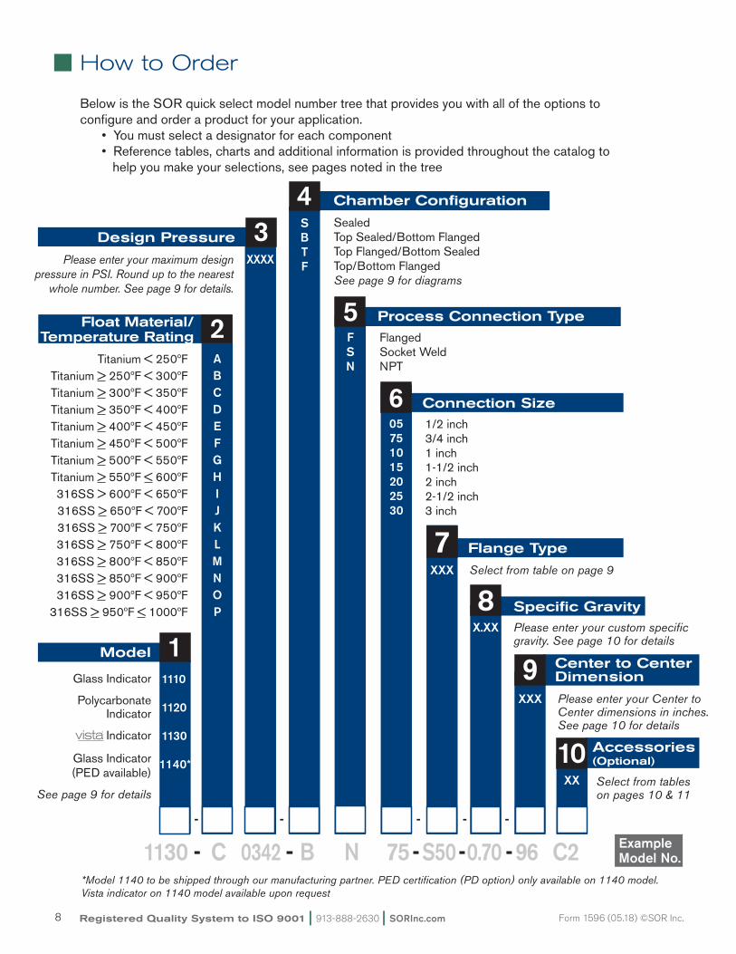
How to Order
Below is the SOR quick select model number tree that provides you with all of the options to configure and order a product for your application. •Youmustselectadesignatorforeachcomponent •Referencetables,chartsandadditionalinformationisprovidedthroughoutthecatalogto
helpyoumakeyourselections,seepagesnotedinthetree
1130 - C 0342 - B N 75 - S50 - 0.70 - 96 C2 Example Model No.
5 Process Connection Type
FlangedSocket WeldNPT
FSN
2ABCDEFGHIJKLMNOP
7 Flange Type
XXX Select from table on page 9
8 Specific GravityX.XX Please enter your custom specific
gravity. See page 10 for details
10 Accessories(Optional)
XX Select from tables on pages 10 & 11
9 Center to Center Dimension
XXX Please enter your Center to Center dimensions in inches. See page 10 for details
6 1/2 inch3/4 inch1 inch1-1/2 inch2 inch2-1/2 inch3 inch
Connection Size05751015202530
Model 1 1110
1120
1130
1140*
Glass Indicator
Polycarbonate Indicator
Indicator
Glass Indicator(PED available)
See page 9 for details
4SBTF
Chamber Configuration
SealedTop Sealed/Bottom FlangedTop Flanged/Bottom SealedTop/Bottom FlangedSee page 9 for diagrams
- - - - -
*Model 1140 to be shipped through our manufacturing partner. PED certification (PD option) only available on 1140 model. Vista indicator on 1140 model available upon request
2Float Material/Temperature Rating
3Design Pressure
XXXXPlease enter your maximum design pressure in PSI. Round up to the nearest
whole number. See page 9 for details.
Titanium < 250ºFTitanium > 250ºF < 300ºFTitanium > 300ºF < 350ºFTitanium > 350ºF < 400ºFTitanium > 400ºF < 450ºFTitanium > 450ºF < 500ºFTitanium > 500ºF < 550ºFTitanium > 550ºF < 600ºF316SS > 600ºF < 650ºF 316SS > 650ºF < 700ºF 316SS > 700ºF < 750ºF 316SS > 750ºF < 800ºF 316SS > 800ºF < 850ºF 316SS > 850ºF < 900ºF 316SS > 900ºF < 950ºF
316SS > 950ºF < 1000ºF
SORInc.com | 913-888-2630 | Registered Quality System to ISO 9001 9Form 1596 (05.18) ©SOR Inc.
How to Order
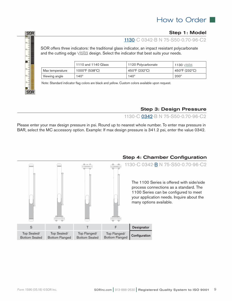
Step 1: Model
1130-C 0342-B N 75-S50-0.70-96-C2
SORoffersthreeindicators:thetraditionalglassindicator,animpactresistantpolycarbonateand the cutting edge design. Select the indicator that best suits your needs.
1110 and 1140 Glass 1120 Polycarbonate 1130
Max temperature 1000ºF (538ºC) 450ºF (232ºC) 450ºF (232ºC)
Viewing angle 140º 140º 200º
Note: Standard indicator flag colors are black and yellow. Custom colors available upon request.
Step 4: Chamber Configuration
1130-C 0342-B N 75-S50-0.70-96-C2
The 1100 Series is offered with side/side process connections as a standard. The 1100 Series can be configured to meet your application needs. Inquire about the many options available.
Step 3: Design Pressure
1130-C 0342-B N 75-S50-0.70-96-C2
Please enter your max design pressure in psi. Round up to nearest whole number. To enter max pressure in BAR,selecttheMCaccessoryoption.Example:Ifmaxdesignpressureis341.2psi,enterthevalue0342.
S B T F Designator
Top Sealed/ Bottom Sealed
Top Sealed/ Bottom Flanged
Top Flanged/ Bottom Sealed
Top Flanged/ Bottom Flanged Configuration
Registered Quality System to ISO 9001 | 913-888-2630 | SORInc.com10 Form 1596 (05.18) ©SOR Inc.
How to Order
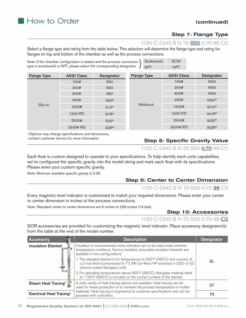
Eachfloatiscustomdesignedtooperatetoyourspecifications.Tohelpidentifyeachunitscapabilities,we’ve configured the specific gravity into the model string and mark each float with its specifications. Please enter your custom specific gravity. Note: Minimum available specific gravity is 0.35.
Step 8: Specific Gravity Value
1130-C 0342-B N 75-S50-0.70-96-C2
Step 9: Center to Center Dimension
Every magnetic level indicator is customized to match your required dimensions. Please enter your center to center dimension in inches of the process connections. Note: Standard center to center dimensions are 6 inches to 228 inches (19 feet).
1130-C 0342-B N 75-S50-0.70-96-C2
Step 10: Accessories
1130-C 0342-B N 75-S50-0.70-96-C2SOR accessories are provided for customizing the magnetic level indicator. Place accessory designator(s) from the table at the end of the model number.
Accessory Description DesignatorInsulation Blanket Insulation is recommended when indicators are to be used under extreme
temperature conditions. Factory installed, removable insulation blankets are available in two configurations.
1. The standard blanket is for temperatures to 500˚F (260˚C) and consists of a 2 inch thick (compressed to 1”), 6# Cer-Wool HP enclosed in 3201-2-SS silicone coated fiberglass cloth.
2. For operating temperatures above 500˚F (260˚C), fiberglass material rated to 1100˚F (593˚C) is included on the contact surface of the blanket.
BL
Steam Heat Tracing* A wide variety of heat tracing options are available. Heat tracing can be used for freeze protection or to maintain the process temperature of molten materials. Heat tracing is engineered to customer specifications and can be provided with controllers.
ST
Electrical Heat Tracing* TR
Flange Type ANSI Class Designator
Slip-on
150# S50
300# S30
600# S60
900# S90*1500# S15*
1500 RTJ S1R*2500# S25*
2500# RTJ S2R*
Flange Type ANSI Class Designator
Weldneck
150# W50
300# W30
600# W60
900# W90*1500# W15*
1500 RTJ W1R*2500# W25*
2500# RTJ W2R**Optionsmaychangespecificationsanddimensions,contact customer service for more information.
(continued)
Select a flange type and rating from the table below. This selection will determine the flange type and rating for flanges on top and bottom of the chamber as well as the process connections.
Step 7: Flange Type
1130-C 0342-B N 75-S50-0.70-96-C2
Socketweld SCW
NPT NPT}Note: If the chamber configuration is sealed and the process connection typeissocketweldorNPT,pleaseselectthecorrespondingdesignator.
SORInc.com | 913-888-2630 | Registered Quality System to ISO 9001 11Form 1596 (05.18) ©SOR Inc.
How to Order
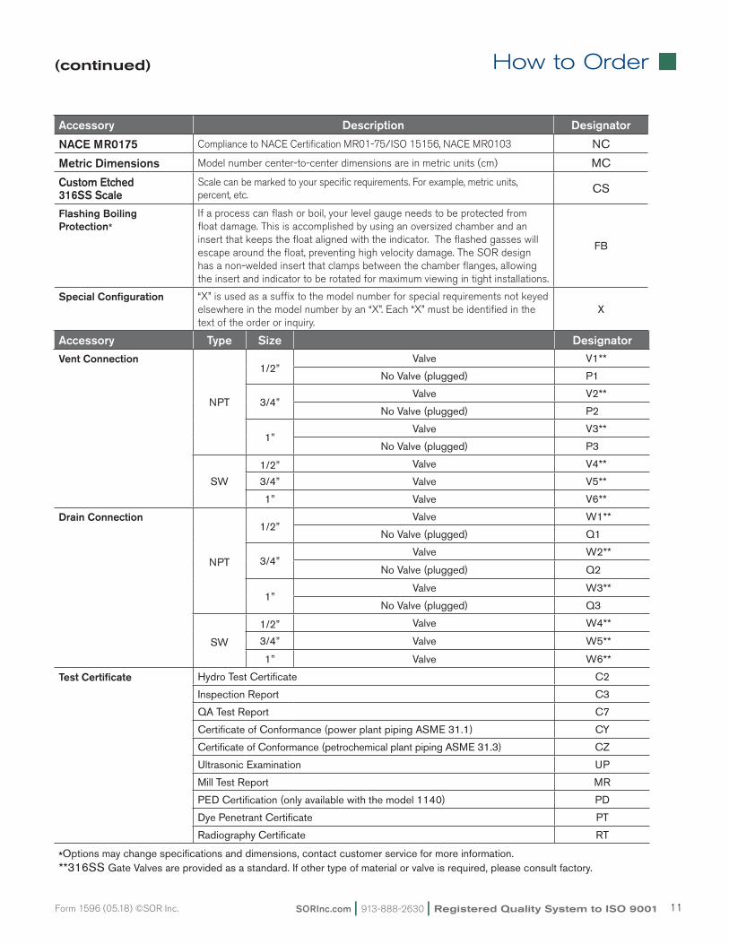
Accessory Type Size DesignatorVent Connection
NPT
1/2”Valve V1**
No Valve (plugged) P1
3/4”Valve V2**
No Valve (plugged) P2
1”Valve V3**
No Valve (plugged) P3
SW
1/2” Valve V4**
3/4” Valve V5**
1” Valve V6**
Drain Connection
NPT
1/2”Valve W1**
No Valve (plugged) Q1
3/4”Valve W2**
No Valve (plugged) Q2
1”Valve W3**
No Valve (plugged) Q3
SW
1/2” Valve W4**
3/4” Valve W5**
1” Valve W6**
Test Certificate Hydro Test Certificate C2
Inspection Report C3
QA Test Report C7
Certificate of Conformance (power plant piping ASME 31.1) CY
Certificate of Conformance (petrochemical plant piping ASME 31.3) CZ
Ultrasonic Examination UP
Mill Test Report MR
PED Certification (only available with the model 1140) PD
Dye Penetrant Certificate PT
Radiography Certificate RT
*Optionsmaychangespecificationsanddimensions,contactcustomerserviceformoreinformation.**316SS GateValvesareprovidedasastandard.Ifothertypeofmaterialorvalveisrequired,pleaseconsultfactory.
(continued)
Accessory Description Designator
NACE MR0175 Compliance to NACE Certification MR01-75/ISO 15156, NACE MR0103 NC
Metric Dimensions Model number center-to-center dimensions are in metric units (cm) MC
Custom Etched 316SS Scale
Scale can be marked to your specific requirements. For example, metric units, percent, etc. CS
Flashing BoilingProtection*
If a process can flash or boil, your level gauge needs to be protected from float damage. This is accomplished by using an oversized chamber and an insert that keeps the float aligned with the indicator. The flashed gasses will escape around the float, preventing high velocity damage. The SOR design has a non-welded insert that clamps between the chamber flanges, allowing the insert and indicator to be rotated for maximum viewing in tight installations.
FB
Special Configuration “X” is used as a suffix to the model number for special requirements not keyed elsewhere in the model number by an “X”. Each “X” must be identified in the text of the order or inquiry.
X
Registered Quality System to ISO 9001 | 913-888-2630 | SORInc.com12 Form 1596 (05.18) ©SOR Inc.
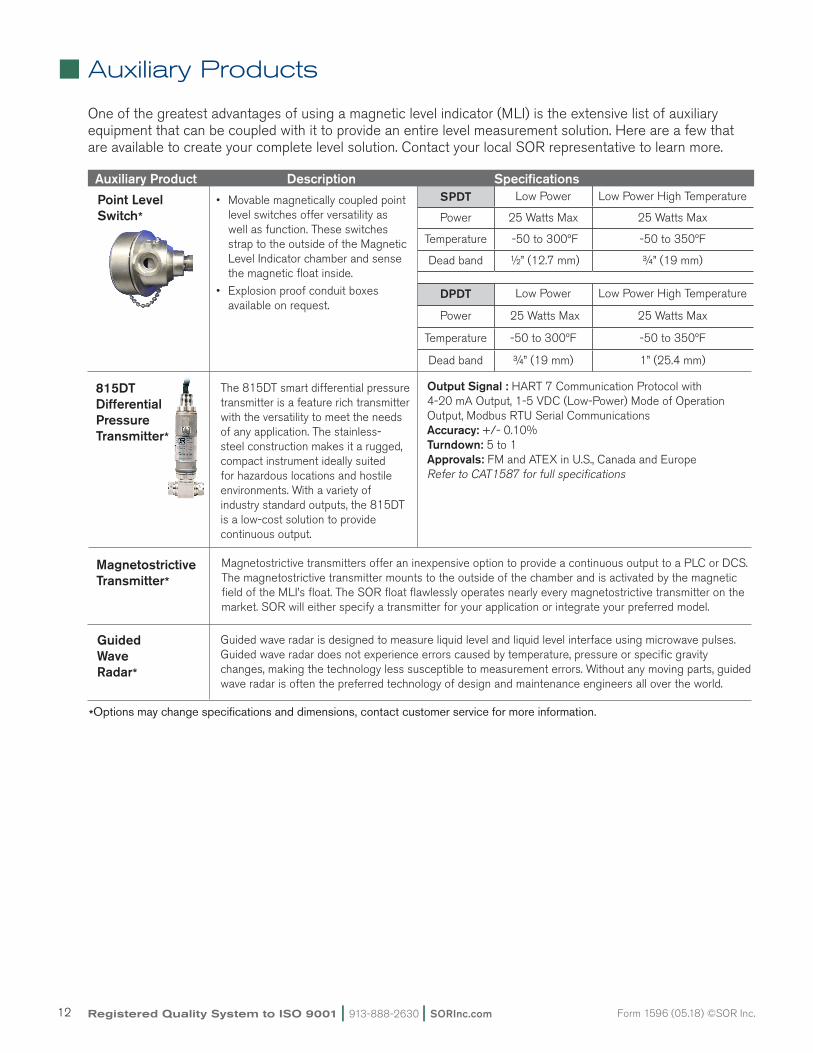
SPDT Low Power Low Power High Temperature
Power 25 Watts Max 25 Watts Max
Temperature -50 to 300ºF -50 to 350ºF
Dead band ½” (12.7 mm) ¾” (19 mm)
DPDT Low Power Low Power High Temperature
Power 25 Watts Max 25 Watts Max
Temperature -50 to 300ºF -50 to 350ºF
Dead band ¾” (19 mm) 1” (25.4 mm)
Auxiliary Products
Auxiliary Product Description Specifications
One of the greatest advantages of using a magnetic level indicator (MLI) is the extensive list of auxiliary equipment that can be coupled with it to provide an entire level measurement solution. Here are a few that are available to create your complete level solution. Contact your local SOR representative to learn more.
Magnetostrictive transmitters offer an inexpensive option to provide a continuous output to a PLC or DCS. The magnetostrictive transmitter mounts to the outside of the chamber and is activated by the magnetic field of the MLI’s float. The SOR float flawlessly operates nearly every magnetostrictive transmitter on the market. SOR will either specify a transmitter for your application or integrate your preferred model.
Magnetostrictive Transmitter*
Point Level Switch*
GuidedWaveRadar*
815DTDifferentialPressureTransmitter*
Guidedwaveradarisdesignedtomeasureliquidlevelandliquidlevelinterfaceusingmicrowavepulses.Guidedwaveradardoesnotexperienceerrorscausedbytemperature,pressureorspecificgravitychanges, making the technology less susceptible to measurement errors. Without any moving parts, guided wave radar is often the preferred technology of design and maintenance engineers all over the world.
The 815DT smart differential pressure transmitter is a feature rich transmitter with the versatility to meet the needs of any application. The stainless-steel construction makes it a rugged, compact instrument ideally suited for hazardous locations and hostile environments. With a variety of industry standard outputs, the 815DT is a low-cost solution to provide continuous output.
Output Signal : HART 7 Communication Protocol with 4-20 mA Output, 1-5 VDC (Low-Power) Mode of Operation Output, Modbus RTU Serial CommunicationsAccuracy: +/- 0.10%Turndown: 5 to 1Approvals: FM and ATEX in U.S., Canada and EuropeRefer to CAT1587 for full specifications
• Movable magnetically coupled point level switches offer versatility as well as function. These switches strap to the outside of the Magnetic Level Indicator chamber and sense the magnetic float inside.
• Explosion proof conduit boxes available on request.
*Optionsmaychangespecificationsanddimensions,contactcustomerserviceformoreinformation.
SORInc.com | 913-888-2630 | Registered Quality System to ISO 9001 13Form 1596 (05.18) ©SOR Inc.
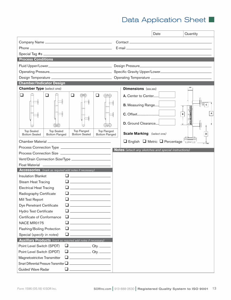
Chamber/Indicator Design
14685 W. 105th Street, Lenexa, KS 66215 • 913-888-2630 • 800-676-6794 • Fax 913-888-0767 • sorinc.com
1100 Series Magnetic Level IndicatorApplication Data Sheet
Company Name Contact
Phone E-mail
Special Tag #s
Chamber Type (select one)
Registered Quality System to ISO 9001 Form 1610 (12.16) ©SOR Inc.
Fluid Upper/Lower Design Pressure
Operating Pressure Specific Gravity Upper/Lower
Design Temperature Operating Temperature
Process Conditions
Date
Insulation Blanket q
Steam Heat Tracing q
Electrical Heat Tracing q
Radiography Certificate q
Mill Test Report q
Dye Penetrant Certificate q
Hydro Test Certificate q
Certificate of Conformance q
NACE MR0175 q
Flashing/Boiling Protection q
Special (specify in notes) q
Accessories (mark as required add notes if necessary)
Quantity
Notes (attach any sketches and special instructions)
Chamber Material
Process Connection Type
Process Connection Size
Vent/Drain Connection Size/Type
Float Material
A. Center to Center......
B. Measuring Range.....
C. Offset..........................
D. Ground Clearance....
Dimensions (xxx.xxx)
Auxillary Products (mark as required add notes if necessary)
Top SealedBottom Flanged
Top FlangedBottom Sealed
Top FlangedBottom Flanged
Top SealedBottom Sealed
q q qq
Scale Marking (select one)
q English q Metric q Percentage
Point Level Switch (SPDT) q Qty.
Point Level Switch (DPDT) q Qty.
Magnetostrictive Transmitter q
Smart Differential Pressure Transmitter q
Guided Wave Radar q
Data Application Sheet
Registered Quality System to ISO 9001 | 913-888-2630 | SORInc.com14 Form 1596 (05.18) ©SOR Inc.
REGIONAL OFFICES
China
SOR China | Beijing, China | [email protected]
+86 (10) 5820 8767 | Fax +86 (10) 58 20 8770
Middle East
SOR Measurement & Control Equipment Trading DMCC | Dubai, UAE
[email protected] | +971 4 363 3637 | Fax + 1 913 312 3596
SOR Inc. | Lenexa, KS USA | 913-888-2630 | Fax 913-888-0767 | SORInc.com