1.1 risk assessment -...
TRANSCRIPT
Pre-drill EIA for the NELP block MB-OSN-2005/3 (Risk Assessment) 2017
1
RISK ASSESSMENT
1.1 RISK ASSESSMENT
ONGC plans to drill one exploratory well and the exploratory drilling will be taken up in the
Block MB-OSN-2005/3 having an area of 1685 km2, and bathymetry ranging from 102~107 m, during
this phase of exploration.
Drilling will be performed using a self-contained Mobile Offshore Drilling Unit (MODU), a
Floater rig capable of performing shallow water drilling. Well testing will be conducted in the event of
discovery of hydrocarbon at such formation to establish hydrocarbon potential in terms of flow rates and
reservoir pressure. Following drilling and well testing activities, wells will be permanently abandoned or
sealed off for further development. Once well has been secured and all necessary equipment has been
retrieved, MODU will be mobilized to the next drill location.
The Risk Assessment encompasses identification of risks involved in the drilling process
and the associated activities in the drilling program, and assessment of probability of certain
consequences.
1.1.1. STAGES FOR WHICH RISK ASSESSMENTS ARE UNDERTAKEN
Exploration drilling activity can be broken up into a series of stages during which different risk
assessments are undertaken:
Pre-operational assessments and regulatory approvals
Well design
Selection of rig, equipment and services
Pre-mobilization, mobilization
Drilling
De-mobilization
The Risk Assessment ascribed here has been undertaken prior to commencing of drilling
operation, and as part of the regulatory requirements, involving evaluation and disclosure of major risks
to the members of the Expert Appraisal Committee (EAC) of MoEF and other regulators, and
Pre-drill EIA for the NELP block MB-OSN-2005/3 (Risk Assessment) 2017
2
demonstrates that the exploratory wells, in principle, can be drilled in a manner not resulting in harm to
individuals or damage to the environment.
This assessment relies on environmental and social sensitivities associated in the region,
data on past accidents in the oil and gas industry, information on past E&P activities undertaken by
ONGC in general and specifically in this area / region, and HSE management systems of ONGC. This
study however has certain limitations for the absence of sufficient details of the Drilling Rig or
associated support systems to be deployed for the proposed exploratory drilling program.
This report on Quantitative Risk Assessment (QRA) aims at providing a systematic and
syntactic analysis of the major risks that could arise as a result of offshore exploration activities of
ONGC in the MB-OSN-2005/3 block.
The QRA process outlines rationale behind the identified risks based on their significance
and also provides for appropriate preventive and risk mitigation measures. It is anticipated that the
results of the QRA would provide valuable inputs for the overall project planning, ONGC‟s existing IMS
and the DSS (Decision Support System) for effectively addressing the identified risk to ensure that the
project risks stay at „As Low As Reasonably Practicable (ALARP)‟ levels at all times during project
implementation. In addition, the QRA will also help in assessing risks arising from potential emergency
situations like a large oil spill and develop a structured Emergency Response Plan (ERP) to restrict
damage to personnel, infrastructure and the environment.
The risk study for the offshore project has considered all aspects of operation of the MODU
and other associated activities during the exploratory phase. Oil spills, loss of well control / blow-out,
vessel collisions, process leaks and helicopter crashes constitute the major potential hazards that may
be associated with the project. External and environmental risk factors (e.g., collisions with passing
merchant vessels, severe weather and seismic events) were considered in the assessment. However,
the risks or hazards associated with development and production program of exploratory wells has
been precluded for it being beyond the scope of the study.
The following section describes the methodology of the risk assessment study and then
presents the assessment for each of the potential risk separately.
1.1.1.1 OBJECTIVE OF QRA
The overall objective of the QRA is to identify the main contributors of major risks arising
from the offshore project which in turn will help in understanding the nature of hazards, evaluate and
Pre-drill EIA for the NELP block MB-OSN-2005/3 (Risk Assessment) 2017
3
prioritize them keeping in mind the ALARP principle and then suggest practicable targets for risk
reduction, if any. The specific objectives of this risk assessment are to:
Identify potential risk scenarios that may arise from operation of supply ships, helicopter
transport, etc.
Analyze the possible likelihood and frequency of such risk scenarios by reviewing
historical accident data.
Predict the consequences of such potential risk scenarios and if consequences are high,
establish the same by through application of quantitative simulations.
Recommend feasible preventive and mitigation measures as well as provide inputs for
drawing up an Emergency Response Plan (ERP) for the project.
The objectives of the QRA meet the criteria set for risk assessment for offshore operations in the
Petroleum and Natural Gas (Safety in Offshore Operations) Rules, 2008.
1.1.1.2 RISK ASSESSMENT METHODOLOGY
Risk associated with offshore oil and gas activities has two main elements - the risk of an
event happening - an oil spill, and the probability that that it will impact a receptor, such as an
ecologically sensitive area. For the purposes of this assessment, a risk ranking methodology based on
likelihood and consequence has been developed in line with specific criteria defined by ONGC for this
project, and represented in the form of a risk matrix.
The risk matrix is a widely accepted and standardized method of semi-quantitative risk
assessment and is preferred over purely quantitative methods, given its inherent limitations to define a
risk event with certainty. The application of this tool has resulted in the prioritization of the potential risk
events for the proposed drilling operations thus providing the basis for drawing up risk mitigation
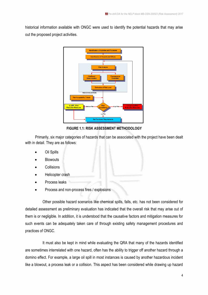
measures leading to formulation of plans for risk and emergency management. The overall approach is
summarized in the Figure 1.1.
1.1.1.3 HAZARD IDENTIFICATION
Hazard identification for the purposes of the QRA comprised of a review of the project and
associated activity related information provided by ONGC. In addition, guidance provided by knowledge
platforms/portals of the upstream oil & gas industry including OGP, ITOPF and DNV as well as
Pre-drill EIA for the NELP block MB-OSN-2005/3 (Risk Assessment) 2017
4
historical information available with ONGC were used to identify the potential hazards that may arise
out the proposed project activities.
FIGURE 1.1: RISK ASSESSMENT METHODOLOGY
Primarily, six major categories of hazards that can be associated with the project have been dealt
with in detail. They are as follows:
Oil Spills
Blowouts
Collisions
Helicopter crash
Process leaks
Process and non-process fires / explosions
Other possible hazard scenarios like chemical spills, falls, etc. has not been considered for
detailed assessment as preliminary evaluation has indicated that the overall risk that may arise out of
them is or negligible. In addition, it is understood that the causative factors and mitigation measures for
such events can be adequately taken care of through existing safety management procedures and
practices of ONGC.
It must also be kept in mind while evaluating the QRA that many of the hazards identified
are sometimes interrelated with one hazard, often has the ability to trigger off another hazard through a
domino effect. For example, a large oil spill in most instances is caused by another hazardous incident
like a blowout, a process leak or a collision. This aspect has been considered while drawing up hazard
Pre-drill EIA for the NELP block MB-OSN-2005/3 (Risk Assessment) 2017
5
mitigation measures and such linkages (among hazards) has also been given due Importance for
managing hazards and associated risks in a composite manner through ONGC safety management
system and the Emergency Response Plan.
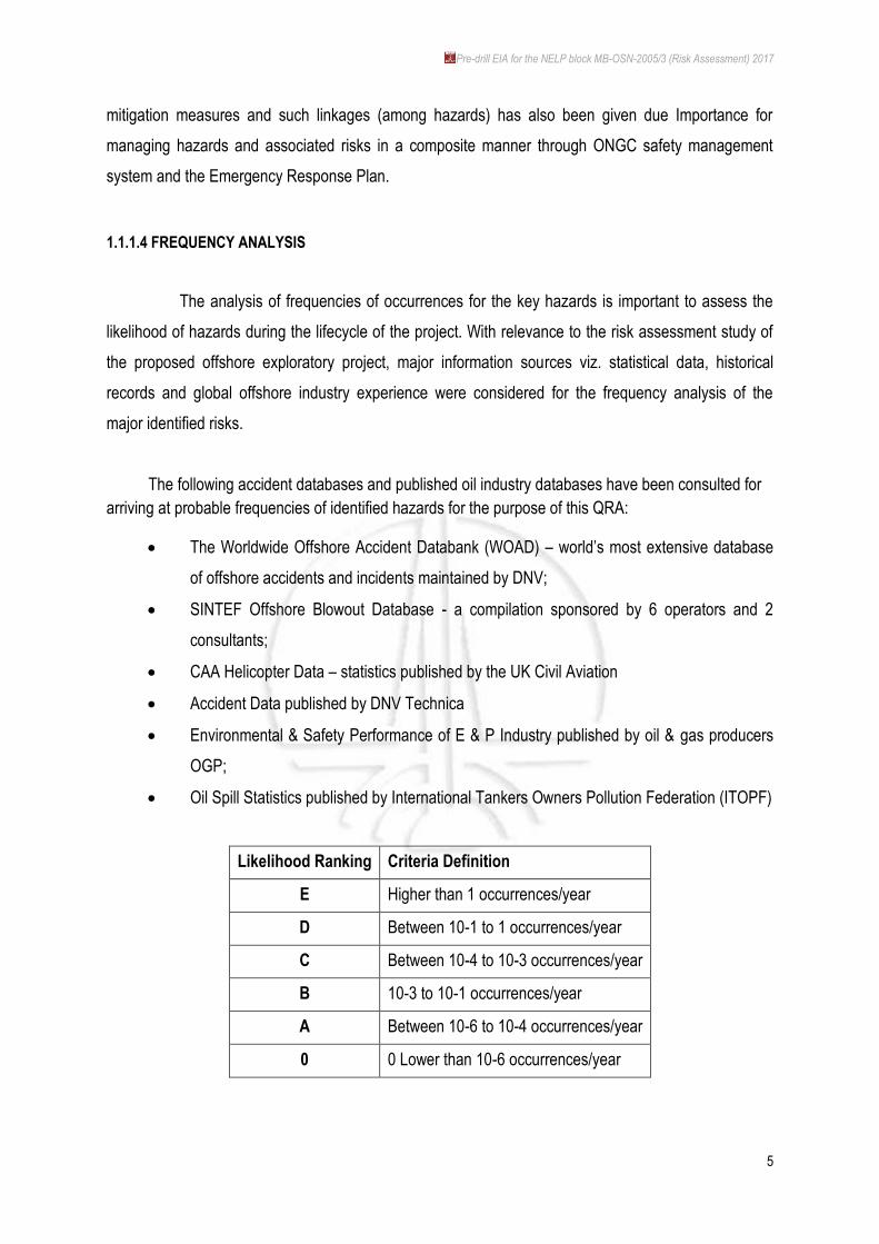
1.1.1.4 FREQUENCY ANALYSIS
The analysis of frequencies of occurrences for the key hazards is important to assess the
likelihood of hazards during the lifecycle of the project. With relevance to the risk assessment study of
the proposed offshore exploratory project, major information sources viz. statistical data, historical
records and global offshore industry experience were considered for the frequency analysis of the
major identified risks.
The following accident databases and published oil industry databases have been consulted for
arriving at probable frequencies of identified hazards for the purpose of this QRA:
The Worldwide Offshore Accident Databank (WOAD) – world‟s most extensive database
of offshore accidents and incidents maintained by DNV;
SINTEF Offshore Blowout Database - a compilation sponsored by 6 operators and 2
consultants;
CAA Helicopter Data – statistics published by the UK Civil Aviation
Accident Data published by DNV Technica
Environmental & Safety Performance of E & P Industry published by oil & gas producers
OGP;
Oil Spill Statistics published by International Tankers Owners Pollution Federation (ITOPF)
Likelihood Ranking Criteria Definition
E Higher than 1 occurrences/year
D Between 10-1 to 1 occurrences/year
C Between 10-4 to 10-3 occurrences/year
B 10-3 to 10-1 occurrences/year
A Between 10-6 to 10-4 occurrences/year
0 0 Lower than 10-6 occurrences/year
Pre-drill EIA for the NELP block MB-OSN-2005/3 (Risk Assessment) 2017
6
1.1.1.5 CONSEQUENCE ANALYSIS
In line with the frequency analysis, hazard prediction / consequence analysis exercise has
been done to assess the resulting effects in the event of an accident and their likely impact on project
personnel, infrastructure and environment. The consequences of accidental events on the marine and
social environment have been studied to evaluate any major impact to the aforesaid environment.
Overall, the consequence analysis takes into account the following aspects:
Magnitude of impacts in terms of area involved
Stakeholder concern
Impact on ecology/biodiversity
Time period for natural recovery and cleanup in case a risk scenario unfolding
The following criteria for consequence rankings have been drawn up in context of the possible
environmental consequences in the event of the risk events unfolding during the drilling operations:
Pre-drill EIA for the NELP block MB-OSN-2005/3 (Risk Assessment) 2017
7
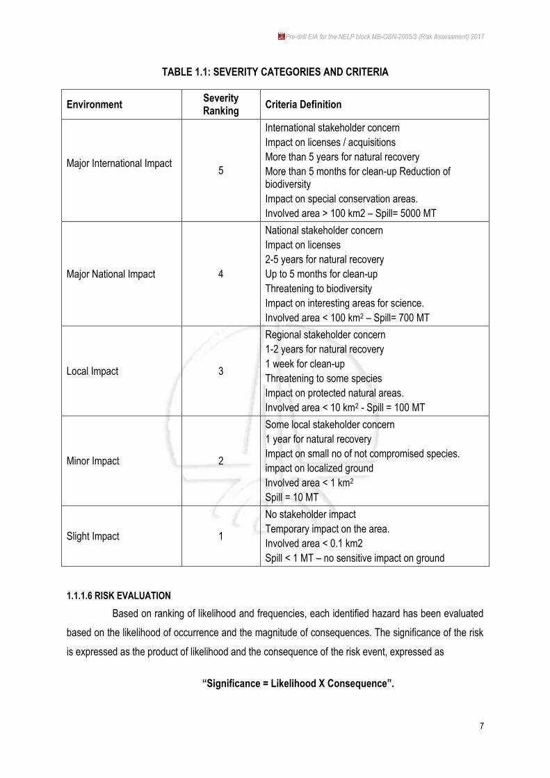
TABLE 1.1: SEVERITY CATEGORIES AND CRITERIA
Environment Severity Ranking
Criteria Definition
Major International Impact
5
International stakeholder concern
Impact on licenses / acquisitions
More than 5 years for natural recovery
More than 5 months for clean-up Reduction of biodiversity
Impact on special conservation areas.
Involved area > 100 km2 – Spill= 5000 MT
Major National Impact 4
National stakeholder concern
Impact on licenses
2-5 years for natural recovery
Up to 5 months for clean-up
Threatening to biodiversity
Impact on interesting areas for science.
Involved area < 100 km2 – Spill= 700 MT
Local Impact 3
Regional stakeholder concern
1-2 years for natural recovery
1 week for clean-up
Threatening to some species
Impact on protected natural areas.
Involved area < 10 km2 - Spill = 100 MT
Minor Impact 2
Some local stakeholder concern
1 year for natural recovery
Impact on small no of not compromised species.
impact on localized ground
Involved area < 1 km2
Spill = 10 MT
Slight Impact 1
No stakeholder impact
Temporary impact on the area.
Involved area < 0.1 km2
Spill < 1 MT – no sensitive impact on ground
1.1.1.6 RISK EVALUATION
Based on ranking of likelihood and frequencies, each identified hazard has been evaluated
based on the likelihood of occurrence and the magnitude of consequences. The significance of the risk
is expressed as the product of likelihood and the consequence of the risk event, expressed as
“Significance = Likelihood X Consequence”.
Pre-drill EIA for the NELP block MB-OSN-2005/3 (Risk Assessment) 2017
8
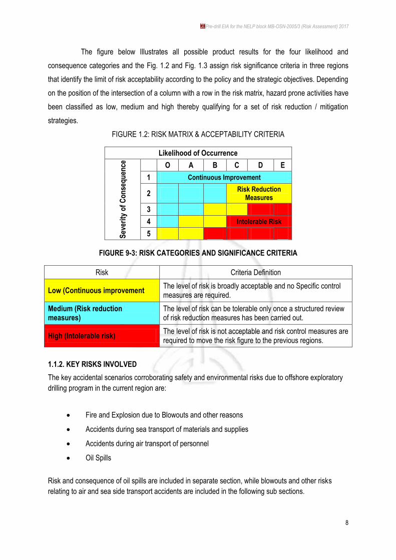
The figure below Illustrates all possible product results for the four likelihood and
consequence categories and the Fig. 1.2 and Fig. 1.3 assign risk significance criteria in three regions
that identify the limit of risk acceptability according to the policy and the strategic objectives. Depending
on the position of the intersection of a column with a row in the risk matrix, hazard prone activities have
been classified as low, medium and high thereby qualifying for a set of risk reduction / mitigation
strategies.
FIGURE 1.2: RISK MATRIX & ACCEPTABILITY CRITERIA
Likelihood of Occurrence
Sev
erit
y o
f C
on
seq
uen
ce
O A B C D E
1 Continuous Improvement
2 Risk Reduction
Measures
3
4 Intolerable Risk
5
FIGURE 9-3: RISK CATEGORIES AND SIGNIFICANCE CRITERIA
Risk Criteria Definition
Low (Continuous improvement The level of risk is broadly acceptable and no Specific control measures are required.
Medium (Risk reduction measures)
The level of risk can be tolerable only once a structured review of risk reduction measures has been carried out.
High (Intolerable risk) The level of risk is not acceptable and risk control measures are required to move the risk figure to the previous regions.
1.1.2. KEY RISKS INVOLVED
The key accidental scenarios corroborating safety and environmental risks due to offshore exploratory
drilling program in the current region are:
Fire and Explosion due to Blowouts and other reasons
Accidents during sea transport of materials and supplies
Accidents during air transport of personnel
Oil Spills
Risk and consequence of oil spills are included in separate section, while blowouts and other risks
relating to air and sea side transport accidents are included in the following sub sections.
Pre-drill EIA for the NELP block MB-OSN-2005/3 (Risk Assessment) 2017
9
1.1.2.1 BLOWOUTS
A blowout in a hydrocarbon exploration activity can be defined as any uncontrolled flow of
formation fluids from the reservoir to the surface, due to formation pressure exceeding the hydrostatic
pressure of the mud or fluid column and failure of blowout prevention measures. For an offshore drilling
activity, blowout events may occur at the drill ship level or subsea and may result in pool /jet fires,
vapour cloud explosions or sometimes may lead to release of toxic gases like Hydrogen Sulphide.
Blowouts during offshore operations may be initiated during both drilling and development
phase and also as a result of external causes viz. earthquakes, ship collision, and structural collapse. In
the context of the proposed project, offshore operations will be limited to exploratory drilling and testing.
Therefore, any incidence of blowout during the aforesaid phases may occur as a result of loss of well
control due to formation fluid entry into well bore, well head damage or loss of containment. The
underlying causes of most of the blowout incidents (excluding external causes) occurring worldwide can
be interpreted as organizational and managerial. An analysis of blowout causes into such factors
attempted for the Marintek database (NSFI 1985) revealed that the main causal factors were improper
maintenance, operational failures and inadequate supervision.
BLOW OUT FREQUENCY ANALYSIS
Blowout frequency estimates are obtained from a combination of incident experience and
associated exposure in a given area over a given time period. Due to limited offshore oil & gas related
activities in the offshore region, blowouts that have occurred at other offshore locations worldwide have
been considered for the blowout frequency analysis. Input data for the frequency analysis of blowout
events were taken from DNV‟s database, viz., WOAD (World Offshore Accident Database). Review of
blowout frequencies from the database reveals a frequency 1.1 X 10⁻² per operation per year for drill
ships (comparable to the MODU to be deployed for the drilling activity) compared to Jack Up Rigs (1.8
X 10-3), and Fixed Platforms (9.3 X 10⁻⁴).
Since the proposed project involves only exploratory drilling, measurement of exposure for
blowout incidents has been determined by considering blowout frequencies during drilling and by the
platform type. The blowout frequency for the proposed 6 wells have been obtained by multiplying the
blowout frequencies per well year by the no of wells drilled, and the time taken for drilling each well.
Pre-drill EIA for the NELP block MB-OSN-2005/3 (Risk Assessment) 2017
10
Estimated frequency for blowout for the proposed drilling operation in exploratory block MB-
OSN-2005/3 is: Probability for blowout from ONGC drilling operations = 1.1 X 10⁻² (prob/ year / drilling
operation) X 1(no of drills) X 0.2 (time taken for each drill in yrs) = 0.2 X10⁻²
BLOW OUT CONSEQUENCES AND EFFECTS
A blowout incident can take a variety of different forms, ranging from a minor leak which can
be stopped within minutes, to a major release which continues out of control for days or even months.
The consequences of a blowout event will to a large extent depend on how the blowout scenario
evolves and the following possible scenarios are likely:
release of oil resulting in a slick or spill on the sea
release of drilling fluids and resulting spill leading to contamination of marine environment
release of toxic / flammable gas which may have deleterious/detrimental effect on the drill
ship personnel
ignition of the flammable gas / oil released resulting in a jet of fire, pool of fire or an
explosion
Ignition of released oil and gas can possibly result in considerable harm. With historical
data, 40% of blowout incidences to have led to significant damage to the drill ship / platform (WOAD
database) and resulted in associated fatalities amongst drilling crew and support personnel present on
the ship / platform. Also, ignition has been recorded world over, on an average, in about 30% of the
blowout cases (SINTEF offshore blowout database). However, on the positive side, with improvement
of offshore drilling technology, number of offshore blowouts occurrences has significantly gone down in
the last decade.
A public domain database maintained by DNV for all offshore hazards including 312 blowouts
worldwide from 1970-96.
RISK RANKING FOR BLOWOUTS
Likelihood Ranking - C
Consequence Ranking - 4
Risk Ranking - 4C (High)
Pre-drill EIA for the NELP block MB-OSN-2005/3 (Risk Assessment) 2017
11
PREVENTIVE AND MITIGATION MEASURES
Blowouts being events which may be catastrophic to any well operation, it is essential to
take up as much a preventive measures as feasible. Following measures would be implemented:
Necessary active barriers (e.g. Blowout Preventer) will be installed to control or contain a
potential blowout.
Close monitoring of drilling activity would be done to check for signs of increasing
pressure, viz., shallow gas formations.
Adequate precautionary measures to be taken in case of a natural event like earthquake
or a cyclone.
1.1.2.2 COLLISIONS INVOLVING MODU:
A collision event is considered for the risk assessment for the impacts on MODU by other
drill ships or other marine vessels working nearby or passing by it. The following possibilities have been
taken into consideration:
support vessels which approach the MODU under their own power including supply
vessels, standby vessels, etc.
Collisions may vary from minor bumps to rare but highly damaging full-speed collisions.
The frequency for such incidences is strongly dependent on the severity of the collisions
included. The types of collisions possible in this are as follows:
On arrival – where the visiting vessel fails to stop when it reached the platform;
Manoeuvering – where the vessel misjudges a turning or approach manoeuver, and the
hits the MODU at a relatively low speed
Drifting – where the vessel loose power or suffers a failure of dynamic positioning and
drifts into the platform because of winds or waves.
The collision frequency would be expected to vary roughly in proportion to the number of
visits, particularly for supply vessels, which are again of a similar pattern. The frequency of collisions
will also depend on the weather conditions prevailing in the offshore region near the coast during the
drilling period, especially for minor collisions. As exact vessel movement data for the ONGC India
operations are not available at this time, an average vessel movement (Technica, 1987) of about 3.6
vessels / week has been assumed.
Assuming the number of visits to the MODU as 5.0 vessels per week, the typical overall
frequency of moderate to severe collision by a support vessel with the MODU can be taken as 1.0X10⁻⁴

Pre-drill EIA for the NELP block MB-OSN-2005/3 (Risk Assessment) 2017
12
per visit. Estimated frequency for support vessel collision for the proposed drilling operation in
exploratory block MB-OSN-2005/3 is:
Total number of visits = 5 / 7 X 210 = 150
Frequency for collision = 1.0 X 10-4 X 150 = 1.5 X 10⁻²
COLLISIONS INVOLVING MODU AND PASSING VESSELS
Collisions with offshore oil structures involving passing vessels are generally very rare
(about 5 % of all reported collisions) but can be potentially very damaging. Probabilities for passing
vessel collisions can be estimated from historical experience. However, the frequencies are uncertain
and statistically insufficient as only few passing vessel collisions have has been reported. Historical
data have limited value because they are often unable to reflect local traffic levels with reasonable
degree of accuracy and also because the sea has few formally defined shipping lanes and ships tend to
follow informal lanes voluntarily between ports.
COLLISIONS INVOLVING SUPPLY AND OTHER VESSELS
There is a negligible probability of supply vessels colliding with other commercial vessels on
route to the MODU while maneuvering near to the Nhava base. These collisions may happen because
of navigational difficulties or because of prevailing traffic density near JNPT. However, the traffic on
local routes is highly regulated and controlled. So the possibility of such collisions happening is
considered to be minimal.
CONSEQUENCES AND EFFECTS
The analysis of collision consequences is generally based on the principle of conservation
of energy. The incident kinetic energy of a vessel on a collision course can be transferred to the MODU
during the impact. The magnitude of energy transfer will depend on the mass of the vessel and on the
square of its speed at the time of impact. However, in the case the collision is as a result of a glancing
blow from a support vessel, where the vessel brushes against the platform, the kinetic energy transfer
is minimal and is expected to cause minimal damage to the MODU. The impact of a full-on collision
may however be more severe and may lead to structural damage to the MODU. The risk to personnel
manning a platform / drill ship from a collision in terms of fatalities or injuries has been historically found
to be very low, if not resulting in a catastrophic incidence like a blowout. It should be noted that the
Pre-drill EIA for the NELP block MB-OSN-2005/3 (Risk Assessment) 2017
13
MODU would be connected to the drilling apparatus at the sea bottom; a collision involving high energy
transfer may lead to a rupture or leak in the riser resulting in a process leak or a blowout.
RISK RANKING FOR VESSEL COLLISION
Likelihood Ranking - C
Consequence Ranking - 3
Risk Ranking - 3C (Medium)
PREVENTIVE AND MITIGATION MEASURES
A Vessel Management Plan will be formulated and implemented to reduce collision risk, both vessel–
vessel and MODU–vessel and will address the following:
Mandatory 500 m safety zone around platform;
Operational restrictions on visiting vessels in bad weather;
Defined vessel no-go areas within safety zone; and
Agreed approach procedures to platform by supply and safety vessels.
1.1.2.3 HELICOPTER CRASHES
The journey to and from offshore installations has historically been one of the main reasons
for accidental death or injury to many offshore workers. For the ONGC India drilling activities, crew
transport to and from the MODU will be taken care of by helicopter for its speed, convenience and good
operability under rough weather conditions.
FREQUENCY PROBABILITY
Several approaches exist to analyze probability of helicopter crash risks. The most common
approach involves the use an overall Fatal Accident Rate (FAR) value (e.g. SINTEF 1990). However,
there are certain inherent deficiencies in adopting this approach in spite of the fact that it provides
convenient risk numbers. A more reasonable approach involves the use of individual risk approach as a
product of 3 components:
Frequency of helicopter accidents per flight;
Proportion of accidents which involve fatalities;
Proportion of personnel on board in fatal accidents who become fatalities.
Pre-drill EIA for the NELP block MB-OSN-2005/3 (Risk Assessment) 2017
14
Taking this approach and considering historical data from the UK sector which is available, while
accounting for both the flying time and number of flying stages involved, the Individual Risk per journey
can be calculated as Individual Risk (IR) per journey = 1.7 X 10⁻⁶ X flying time (hours) + 2.7 X 10⁻⁷ X
No. of stages per journey.
CONSEQUENCES AND EFFECTS
Helicopter crashes with offshore oil & gas exploration and production have happened
routinely in the past, especially in the North Sea offshore operations in Europe, with some resulting in
fatalities or injuries to crew members. In addition to the risk posed to the helicopter occupants,
accidents involving helicopters can also cause damage to the drill ship itself by way of crashing into the
ship during take-off or landing or by an accident when the helicopter is on the helideck. However, the
consequence of such risk may be considered to be small compared to the other risks sources on the
MODU.
RISK RANKING FOR HELICOPTER CRASH
Likelihood Ranking - BC
Consequence Ranking - 3
Risk Ranking - 3B (Medium)
PREVENTIVE AND MITIGATION MEASURES
Following preventive and mitigation measures will be adopted with respect of helicopter operations:
Air worthiness of helicopter to be checked by competent authority before helicopter is
hired by ONGC India.
ONGC India should ensure that the pilot/pilots who will be operating have got appropriate
training on similar craft.
Effective arrangements for coordination would be developed with air traffic control room at
Nhava base, as also in the MODU;
Helicopter operations to be restricted during night time and during bad weather conditions.
All employees who are supposed to travel on helicopters would be receiving basic training
on rescue and survival techniques in the case of a helicopter crash at sea.
Pre-drill EIA for the NELP block MB-OSN-2005/3 (Risk Assessment) 2017
15
1.1.3. RISK MITIGATION MEASURES
1.1.3.1 WELL PLANNING & DESIGN
Exploration wells are designed to manage the uncertainty in the true nature of the well to be
drilled. The possibility of shallow gas, uncertainty in pore-pressure and temperature, porous and
permeable intervals, weak formations, etc. all need to be assessed, and the well design and drilling
program developed to cater for „worse-case‟ scenarios. Offset well data, computation modeling and site
specific survey data allow the geoscientists to provide the drilling engineers with information on the
likely range (probabilistic) and maximum values of key design parameters. The drilling engineer designs
the well (and the associated drilling programme) on the basis of maximum anticipated values.
Explicit risk assessment, in terms of assigning quantitative probabilities of failure to all parts
of the well design, does not feature in the design of a typical exploration well. However, risk
assessment is implicit within the design process, specifically through the adoption of operational
manuals and procedures and industry recognized design approaches by ONGC.
ONGC and other private E&P operators such as RIL have in the past undertaken drilling
activities in the offshore region around the coast of Maharashtra. This has led to a fair amount of
geological information and offset well data from the region, based on which ONGC will be able to plan
and design exploratory wells in the block, with minimal uncertainties and therefore higher probability of
avoiding accidental scenarios such as blowouts.
As per ONGC‟s Management Systems of Offshore Drilling and HSE, and in compliance with
Petroleum and Natural Gas (Safety in Offshore Operations) Rules 2008, ONGC will ensure that:
A Well programme describing the individual activities and the equipment to be used will be
prepared prior to starting well activities
The management system with associated processes, resources and operational
organization will be established;
Steering documents, including technical documents for drilling and well testing operations,
will be made available, in an updated version and the operational personnel shall be
acquainted with it.
Commissioning process prior to startup of facilities for first time or after technical
modifications will be completed
Pre-drill EIA for the NELP block MB-OSN-2005/3 (Risk Assessment) 2017
16
Well barriers:
During drilling and other related well activities, there will at all times be at least two
independent and tested well barriers after surface casing a in place. Well barriers
will be designed in such a manner that unintentional influx, cross flow to
deformation layers and outflow to the external environment is prevented.
Well barriers will be designed in such a manner that their performance can be
verified.
If a barrier fails, during drilling and other related well activities, no other activities will
be undertaken in the well than those to restore the barrier.
When a well is abandoned, the barriers would be designed to provide integrity for
the longest period of time in such a manner, inter alia, that outflow from the well or
leakages to the external environment do not occur.
ONGC will choose well location and well path on the basis of well parameters of
importance, including occurrence of shallow gas, other hydrocarbon bearing
formation layers and distances to adjacent wells and to ensure that it is possible to
drill a relief well from two alternative locations. The well path will be known at all
times.
ONGC will ensure that the necessary actions are planned including setting of casing
above all known shallow gas hazard zones to handle occurrence of situations of shallow
gas or other formation fluids.
During drilling and well activities, drilling and well data will be collected and monitored to
verify the well prognoses, in order that necessary actions may be taken and the well
programme may be adjusted, if necessary.
Well control:
Well control equipment will be designed, installed, maintained, tested and used so
as to provide for well control.
In the case of drilling of top hole sections with riser or conductor, equipment with
capacity to conduct shallow gas and formation fluid away from the facility, until the
personnel has been evacuated, will be installed.
Floating facilities shall have an alternative activation system for handling critical
functions on the blow out preventer.
Pre-drill EIA for the NELP block MB-OSN-2005/3 (Risk Assessment) 2017
17
Accumulator for surface and subsurface well control equipment will have minimum
useable fluid capacity as per industry standards in order to perform closing and
opening sequences as applicable to secure the well.
The pressure control equipment used in well interventions will have remote control
valves with locking devices.
The well intervention equipment will have a remote control blind or shear ram as
close to the Christmas tree as possible
If well control is lost, ONGC will ensure that it shall be possible to regain the well
control by direct intervention or by drilling a relief well.
ONGC will prepare an action plan describing how the lost well control can be
regained
ONGC will set operational limitations in relation to controlled well flow
Securing of wells before abandoning
All wells will be secured before they are abandoned in such a manner that well
integrity remains intact for the period abandoned.
With regard to subsea completed wells, the well integrity will be ensured if the wells
are planned to be temporarily abandoned
Radioactive sources will not be left behind in the well.
In case it is not possible to retrieve the radioactive sources and these have to be left
in the well, ONGC will follow proper abandonment procedure as per guidelines of
the Department of Atomic Energy, Government of India.
Compensator and disconnection systems:
Design of compensator systems will be based on robust technical solutions so that
failures do not lead to unsafe conditions.
Floating facilities shall be equipped with a disconnection system that secures the
well and releases the riser before a critical angle occurs
Drilling fluid system:
The drilling fluid system will be designed in such a manner that it will mix, store,
circulate and clean a sufficient volume of drilling fluid with the necessary properties
to ensure the drilling fluid‟s drilling and barrier functions.
The high pressure part of the drilling fluid system with associated systems will in
addition have capacity and working pressure to be able to control the well pressure
at all times.
Pre-drill EIA for the NELP block MB-OSN-2005/3 (Risk Assessment) 2017
18
Availability of sufficient quantity of drilling fluid weighting material to subdue the well
at any time during the drilling operation will be ensured
Cementing unit:
The cementing unit will be designed in such a manner that it will mix, store and
deliver as exact volume as possible of cement with the necessary properties to
ensure full satisfactory anchoring and barrier integrity
The unit will be designed in such a manner that remains of unmixed chemicals as
well as ready-mixed cement is handled in accordance with the applicable
environment regulations.
If the cementing unit with associated systems is intended to function as backup for
the drilling fluid system, it shall have capacity and working pressure to be able to
control the well pressure at all times.
Casings and anchoring will be such that the well integrity is ensured and the barrier
functions are provided for the life time of the well.
Equipment for completion and controlled well flow
Equipment for completion will provide for controlled influx, well intervention, backup
well barrier elements and plug back activities.
Completion strings will be equipped with necessary down hole equipment including
safety valves
During controlled well flow, the surface and down hole equipment will be adapted to
the well parameters.
Equipment for burning of the well stream will be designed and dimensioned in such
a manner that combustion residues shall not cause pollution of the marine
environment
ONGC will ensure that controlling well pressure through the work string and the well
flow through the choke manifold at any time
1.1.3.2 SELECTION OF EQUIPMENT, SYSTEMS AND PEOPLE
ASSESSING THE ABILITY OF THE DRILLING RIG TO PERFORM THE REQUIRED OPERATION
The water depth, environmental conditions, reservoir and geophysical properties will dictate
the type of rig and equipment required to perform the drilling operation. Highly technical risk
Pre-drill EIA for the NELP block MB-OSN-2005/3 (Risk Assessment) 2017
19
assessments will be undertaken both to demonstrate that the rig is capable of providing an acceptable
working environment, and to determine the limits to which certain operations will be undertaken.
During this phase, the ability of the equipment and systems on the rig to provide a suitable
barrier(s) to well control incidents will be reviewed (e.g., pressure rating and functionality of the BOP).
The ability of a drilling rig to operate at the specific location will be assessed, usually through the
application of an industry recognized site assessment practice. (e.g., Site Specific Assessment of
Mobile Jack-Up Units). The objective being to ensure that the risk of (for example) a structural or
mooring failure does not exceed ONGC‟s and the regulator‟s risk acceptance requirements.
The risk assessment process is, to an extent, embodied within the relevant design and
assessment standards applicable to the particular type of drilling rig. However, detailed, site-specific
risk assessments support the application of these standards, for example the analysis of borehole data
to establish the risk of a punch-through. Where a drilling rig is deemed to be operating close to the
limits of its operating envelope, more detailed risk assessments may be warranted.
The requirements of the following applicable standards for the listed equipment shall be met
to demonstrate that drilling systems are in compliance with requirements of the Petroleum and Natural
Gas (Safety in Offshore Operations) Rules, 2008 and Drilling Rig (MODU) is thus fit for purpose:
Fire and explosion risk assessment on MODU includes hazards from the wells and well
testing operations. Following fire and explosion hazards related to wells are generally considered:
Subsea shallow gas blow out
Shallow gas blow out in cellar deck
Blow out at drill floor
Subsea blowout
HC gas release / ignition in mud processing area
Fire and explosion in well testing areas
Well programs needs to be designed taking into consideration the anticipated hazards as
listed above. MODUs should conform to conventions and codes of International Maritime Organization
(IMO). Fire and explosion risk management at MODU can be ensured by meeting the requirements of
these codes. Following issues have been taken into consideration by MODU code:
Pre-drill EIA for the NELP block MB-OSN-2005/3 (Risk Assessment) 2017
20
Structural fire protection layout plan for decks and bulkheads
Protection of accommodation spaces, service spaces and control locations
Means of escape
Fire pumps, fire mains, hydrants and hoses
Fire extinguishing systems in machinery spaces and in spaces containing fired processes
Portable fire extinguishers in accommodation, service and working spaces
Arrangements in machinery and working spaces
Fire detection and alarm system
Gas detection and alarm system
Fireman‟s outfit
Provisions for helicopter facilities
Fire control plan
Ensuring fit for purpose status of fire extinguishing appliances (operational readiness and
maintenance is detailed in MODU Code 2009)
Number and type of portable extinguishers provided on the MODU would be based on the fire hazards
for the spaces protected.
1.1.3.3 TESTING & MAINTENANCE OF CRITICAL EQUIPMENT
Blowout preventer and other pressure control equipment is the most critical equipment to
avoid major accidents during drilling. Therefore the blow out preventer will be pressure tested regularly
in order to maintain its capability of carrying out its intended functions. The blow out preventer with
associated valves and other pressure control equipment on the facility shall be subjected to a complete
overhaul and shall be recertified at regular intervals based on original equipment manufacturer‟s
recommendations and international standards and recommended practices.
CONTRACTOR MANAGEMENT (DRILLING CONTRACTOR)
Management of major incident risks are by the drilling contractor on the MODU is of interest
to ONGC, and will, therefore, ensure that all major incident risks have been assessed and suitable
controls put in place to reduce the risks to as low as reasonably practicable (ALARP). Pre-mobilization
and pre-drilling assessments will be undertaken by ONGC to ensure that the risk to an individual worker
Pre-drill EIA for the NELP block MB-OSN-2005/3 (Risk Assessment) 2017
21
is as low as reasonably practicable. Typically this is demonstrated through the analysis and summation
of all the individual risks and how they impact different classes of offshore personnel.
The major incident risks for which some level of risk assessment is undertaken normally include:
Hydrocarbon releases resulting in fires, explosions or asphyxiation
Structural failure (environmental overload, foundation failure, seismic etc.)
Mooring failure (loss of location keeping and secondary impacts)
Ship Collision
Helicopter operations
Lifting operations and dropped objects (with major incident potential)
The nature of the risk assessment exercise undertaken for each of the risk types varies from
analysis of past incident data, to the detailed assessment of blast overpressure resulting from
hydrocarbon releases of varying sizes and from different locations.
1.1.3.4 SELECTION OF SUPPORT SERVICES
The proposed drilling operations will require some level of 3rd party support services which
typically include helicopter operations, standby and supply vessels, services and equipment on the rig,
onshore supply base and so on. Associated with each of these activities some level of risk assessment
will be undertaken by ONGC. These risk assessments will, for example, drive the need to develop
„bridging arrangements‟ between the contractors that contribute to the management of a particular
activity and the risks that arise from it. However, since ONGC is an experienced E&P operator owning
and/or contracting such support services – Risk Management is built in selection, supervision, and
monitoring these support services.
1.1.3.5 ENSURING MARINE INTEGRITY
1. Stability:
ONGC will ensure that floating facilities are in accordance with the requirements contained
in the applicable standards concerning stability, water tightness and watertight and
weather tight closing means on mobile offshore units.
Pre-drill EIA for the NELP block MB-OSN-2005/3 (Risk Assessment) 2017
22
There will be weight control systems on floating facilities, which will ensure that weight,
weight distribution and centre of gravity are within the design assumptions and equipment
and structural parts will be secured against displacements to affect stability.
2. Anchoring, mooring and positioning:
Floating facilities will have systems to enable them to maintain their position at all times
and, if necessary, be able to move away from the position in the event of a situation of
hazard and accident.
Dynamic positioning systems will be designed in such a manner that the position can be
maintained in the event of defined failures and damage to the system, in case of
accidents.
During marine operations, necessary actions will be taken in such a manner that the
probability of situations of hazard and accident is avoided and those who take part in the
operations are not injured.
Requirements will be set to maintaining position in respect of vessels and facilities during
implementation of such operations, and criteria will be set up for commencing and
suspension of activities.
3. Collision risk management
The Offshore Installation Manager will be the overall authority for safe operations within
the safety zone of installation.
ONGC will ensure that a collision risk management system is implemented and
maintained wherein following shall be inter alia included –
suitability of attendant vessels and off take tankers and competence of their crew;
assessment of probability of collision peculiar to the installation and its location;
provision of necessary risk reduction and control measures;
appropriate procedures and communications for managing operations of attendant
vessels developed jointly with marine service providers;
provision of appropriate equipment and procedures for detecting and assessing the
actions of vessels intruding into the safety zone;
provision of competent personnel with an appropriate level of marine knowledge;
provision of appropriate evacuation and rescue procedures and facilities; and
regular audit and updating of the above systems.
Pre-drill EIA for the NELP block MB-OSN-2005/3 (Risk Assessment) 2017
23
4. Control in the safety zone
The master of the attendant vessel or off take tanker will comply with instructions of the
Offshore Installation Manager when in a safety zone.
The master of the attendant vessel or off take tanker will be responsible for safety of his
crew, the safe operation of attendant vessel or off take tanker and for avoiding collision
with the installation or associated facilities.
5. Operations in rough weather conditions
The operator will ensure safe working in adverse weather and tidal conditions and identify
the rough weather conditions when the operations are to be discontinued and evacuations
carried out, as required.
The operator will ensure that transfer of personnel and cargo between the vessel and
installation is carried out under safe weather conditions and such transfers should be
stopped during adverse or unsuitable weather conditions
6. Cargo management
The operator will ensure optimization of cargo trips, from and to the shore, and cargo handling time at
installation by efficient planning of cargo supplies through containerization, pre-slinging of cargo etc.
1.1.4. H2S EMISSION CONTROL PLANS
H2S production is not envisaged in these wells, but due to exploratory nature of the wells,
contingency plan for emergencies are provided herewith:
1.1.4.1 DETECTION AND ALARM SYSTEMS
The system comprises of H2S sensors located at pre-determined points. In air conditioned
or ventilated areas, detectors will be installed at the fresh air inlets (ducts, entrance ways etc.). Outside,
detectors are required to be installed on gas carrying equipment (well nipple, shale shaker, mud, pits,
drillers‟ stands etc.).
The alarm systems are located near potential leaks, such as the shaft gland connection,
flanges etc. It is pure alarm system with two warning stages and cannot trigger emergency shutdown
alone. The two levels of alarm are as follows:
Pre-drill EIA for the NELP block MB-OSN-2005/3 (Risk Assessment) 2017
24
10 ppm H2S level alarm triggers a light signal but does not indicate danger for all. At this
stage persons are instructed to stand by to check the installation after announcement on
public address system (PA) by the tool pusher, otherwise, to proceed to the upwind side
20 ppm H2S high level triggers a sound alarm and also red light on the control panel.
Emergency alarm is sounded by two short rings of bell intermittently. At this stage
breathing equipment is to be used immediately and the hazard area be vacated unless the
tool pusher give other instruction or announcement over the Public Address System.
H2S Conditions H2S (ppm) measure from Danger
to Life Action
Open air Core/Drill string
Normal operations No H2S potential None None
Watch Potential H2S None Monitor
Alert 1 - 19 NA None Monitor, use PA as needed
Danger 20 - 49 >20 Moderate Stop coring operation
Emergency >50 NA Extreme Evacuate to safe areas
1.1.4.2 VISUAL WARNING SIGNS
In case of high level H2S alarm, the following warning signs should be displayed to alert
helicopter and vessels in the vicinity of the drilling rig.
Red flag 90cm X 60 cms on each side of the rig.
Danger boards painted yellow with black lettering 30 cms high indicating "DANGER H2S".
1.1.4.3 MUSTER LOCATIONS AND ESCAPE ROUTE
Since H2S is heavier than air, it is likely to settle down at lower levels particularly in still air or
in light winds and cut off the natural escape route to the boat landing; in this situation following is
practiced:
Sufficient stair cases on the upwind side of prevailing winds for escape route up the stairs
or down to the lifeboat.
Muster locations for operating personnel in the event of gas alarm areas, in the open on
the upper deck which can be kept free of H2S by the wind.
1.1.4.4 VENTILATION
Forced air ventilation to disperse any accumulation of H2S will be provided by fans (bug blower) at the
following points:
Pre-drill EIA for the NELP block MB-OSN-2005/3 (Risk Assessment) 2017
25
Shale shaker
Working platforms
Control rooms
1.1.4.5 H2S KICK CONTROL
The control of H2S kick may be achieved either by bulldozing gas back into formation or
circulating it out. The actual method to be adopted will depend upon the condition of the well. When a
gas kick occurs, estimate the quantity of H2S present taking adequate precautionary measures of
wearing self-contained breathing apparatus (SCBA). The following procedure is to be adopted:
Close BOP, monitor SIDPP, SICP & pit gain.
If the concentration is high and cannot be circulated out due to H2S hazard in atmosphere,
bulldoze the gas into formation by pumping through kill line.
Raise mud wt. and pH as required.
Load H2S scavenger like zinc carbonate and ironite sponge as may be necessary in the
active mud pit.
Circulate the gas through choke and degasser and burn off the gas.
The following factors are needed to be kept in view:-
All persons on the drilling floor, shale shaker area, mud pump and tank should put
on self-contained breathing apparatus when the kick is to be circulated out.
Persons who are not required for the control operation are withdrawn to a safe area,
where adequate ventilation is arranged.
Frequent checks with portable H2S gas detector are to be made.
Supply vessels will be directed to stay upwind on power and maintain continuous
radio and visual watch.
1.2. DISASTER MANAGEMENT PLAN
Oil & Natural Gas Corporation Limited is the premiere national oil company engaged in the
exploration and production (E&P) of crude oil and natural gas from offshore as well onshore assets in
Indian and abroad. The inherent risk in the oil well drilling and production are well known and the
management of the risks calls for systematic planning, adopting engineering practices and positive
attitude towards safety & environment protection. It was therefore, necessary to develop a Disaster
Management Plan (DMP) to facilitate necessary actions to meet emergency scenarios.
Pre-drill EIA for the NELP block MB-OSN-2005/3 (Risk Assessment) 2017
26
1.2.1. PURPOSE & SCOPE OF THE PLAN
The disaster management plan would serve the following purpose
To set out the appropriate course of action to mitigate the impact of an emergency event.
The plan provides for a procedure allowing all those involved to mobilize their resources in
an orderly way and to react in time effectively.
To respond immediately to an emergency event to prevent its escalation to a disaster and
also the response in the event of such an escalation. The scope of the plan is to cover all
the emergency situations which can influence the risk under the following situations
Disasters due to natural causes Disasters due to manmade causes (external)
Floods Civil disturbances
Tsunami Terrorist Attack
Hurricane Hostage Crisis
Earthquake Bomb threats
Tornado Potential Offshore Vessel Collision
Lightning Helicopter crash on Helideck in Offshore
Disasters due to manmade causes (operational) Helicopter crash-Ditch in sea
Fires Helicopter Emergency landing
Oil/gas well blowouts Office/Offshore accommodation fire
Toxic gas releases, Dropped object incidents
Oil / Chemical spills, Emergencies to offshore installations
Hydrocarbon Release Diving Incidents
Explosions (unconfined, confined) Man Overboard incidents
The emergency situations mentioned above can escalate to such an extent that the required
level of response would be beyond ONGC‟s own resources available within an Asset and intervention
of corporate level will be necessary to mobilize additional resources not only from various other work
centres of ONGC, but even from outsourcing services internationally. In such cases, DMP shall be
activated by the CMD, ONGC as and when, in his opinion, a national and/or international level
intervention is required for handling the crisis.
1.2.1.1 UPDATING AND EXERCISES
The disaster management plan shall be updated as and when required but at least once in a
year. Also, the plan will be exercised under the chairmanship of the CMD once every year to test the
communication system, action plan and the response of all key agencies within ONGC, govt. of India
and outside resources. Accordingly, a Disaster, scenario will be simulated and the „Emergency
Pre-drill EIA for the NELP block MB-OSN-2005/3 (Risk Assessment) 2017
27
Coordinators‟ as defined by the plant will be required to act in a predetermined way to deal in real time
with the situation. The outcome of the exercise will be taken as input to updating the plan and improve
on the lacunae, if any, on the front of preparedness as well as to plug the loopholes to meet with
emergencies of any extent feasible. The exercise shall include the National Crisis Management
Committee. If in any case the exercise cannot be carried out due to operational reasons the same shall
be done as a table top exercise.
1.2.1.2 DISASTER MANAGEMENT PREPAREDNESS
In case of emergency, Emergency Response Plan (ERP) is activated by the installation
manger. He shall immediately bring it into the notice of the Asset/ Basin Manager/ Chief of Services for
mobilization of resources, should the emergency warrants so, beyond the capability of the installation/
rig/ vessel, as well as to activate the Disaster Management Plan constituting a part of the Regional
Contingency Plan (RCP). In order of affixing the responsibility, the Senior most Asset Manager shall be
the Chief Emergency Coordinator (CEC). In case of his absence the next Senior Asset Manager shall
be the CEC. The CEC shall, on the gravity of the emergency, inform the CMD, Director (HR)-CCEC,
Director-concerned and Director-I/C HSE for intervention of Corporate Disaster Management Group
(CDMG).
Corporate Disaster Management Group (CDMG) will come into action in the following
situation when in case of an Offsite emergency, likely to have effect beyond the installation premises or
an emergency originated from outside the premises of the installation which is likely to effect the
operations of the installation and requires corporate intervention.
1.2.1.3 ON SCENE COORDINATOR
Initial Phase
One who is close enough to the scene of emergency may exercise emergency co-ordination in the
initial phase. Accordingly, the Installation Manager will assume the role of On-Site Coordinator (OSC).
Intermediate Phase
The Chief Emergency Coordinator (CEC) at Asset level may appoint a person, normally locationed at
base to take over the task of OSC at Site Control Room (SCR).
Pre-drill EIA for the NELP block MB-OSN-2005/3 (Risk Assessment) 2017
28
Function
The OSC will make an assessment of the situation; the type and quantity of assistance
required and communicate the same to the Asset ECR. The OSC will mobilize the resources available
at the site, deal with the situation and take such actions as directed by the Chief Emergency
Coordinator at the Asset/ Basin/ Plant. He will transmit situation reports (SITREPS) at regular interval
prefixing a numerical sequence to each message.
1.2.1.4 Site Control Room
Location
The Site Control Room will function at the installation depending upon situation. Alternate site control
room will be set up at the closest installation.
Mobilization
The On-Scene Co-coordinator (OSC) will set up SCR as soon as he becomes aware of the emergency
situation.
Function
To make situation reports (SITREPS) from time to time and take steps to fight the emergency.
Determine the type of assistance required & mobilize the same through ECR.
1.2.1.5 COMMUNICATION
As effective communication is crucial for the overall success of the operation, a
communication flow-chart for such scenario is outlined herewith. In the event of a terrorist act, timely,
accurate communications will be critical for the success and survival. Timely response during
emergency is extremely important.
CEC at the work center must communicate immediately as per the flow chart for first
information in case any emergency is likely to come to the notice of media. This is to ensure that the
management has an authentic update of the emergency to reply to the media.
Pre-drill EIA for the NELP block MB-OSN-2005/3 (Risk Assessment) 2017
29
1.3. OIL SPILL RISK ASSESSMENT
1.3.1. OIL SPILL SCENARIOS
Exploration drilling in offshore areas implies a risk for acute spills to sea. Major incidents are
blowouts during drilling into the reservoir zone. Minor incidents include small spills of crude oil (well
releases), diesel (from the rig or from supply vessels) or hydraulic oil (from the rig). With respect to
environmental risk and oil spill emergency preparedness, the dimensioning incident is a blowout.
The oil spill scenarios have been assessed to classify into:
Most probable spill scenario
Maximum likely spill
Worst case spill
TABLE 1.3.1: OIL SPILL SCENARIOS
Spill Scenario Classification Qty. of oil spilled
Spill due to Rupture of flow lines/ hose during transfer of
diesel from supply vessel to the Drilling Rig (as such these
transfer hoses are likely to have auto shut off valve, but
presuming a scenario where this auto shut off valve is non-
functional and is manually shut off after a reaction time of
15 min)
Most probable
spill scenario
100 MT
(Instantaneous)
Spill of diesel due to collision between supply vessel and
the drilling rig and damage to diesel storage in the supply
vessel
Maximum likely
spill
700 MT
(Instantaneous)
Spill of crude oil / condensate due to well blowout which
takes 2 days to cap
Worst case spill 5000 MT (over a
period of 2 days)
1.3.1.1 Marine and Coastal Features Sensitive to Oil Spills
The block MB-OSN-2005/3 is approximately at a distance of over 160 km off the coast of
Mumbai where no ecologically sensitive areas in the exploration area lie. However, the Marine National
Park and the Marine Sanctuary that lie in the gulf will not come in the specific activities for exploratory
drilling in the block MB-OSN-2005/3. Besides this, the Maharashtra coastline comprises of significant
mangrove patches which could also be sensitive to oil spills in case of large oil spill. The well proposed
to be drilled in this block which is closest to this coast is at a distance of over 160 km.
Pre-drill EIA for the NELP block MB-OSN-2005/3 (Risk Assessment) 2017
30
1.3.1.2 ASSESSMENT OF RISKS DUE TO OIL SPILLS
In absence of sufficient met-ocean data and an oil spill trajectory model validated to Indian
metocean conditions, the assessment of risks due to oil spills is made on the basis of logical analysis.
Quantitative spill trajectory models have not been used as part of this assessment. This assessment is
with respect to seasonal trend of coastal currents. A recent study on “Intra-seasonal variability of
coastal currents in India” (by SSC Shenoi, INCOIS – Dec‟10) indicates that except during the period
June to October of the year, sea currents around the coast (excluding the gulf) are pre-dominantly
towards the northwest. During the monsoon period (i.e., Jun to Oct), the currents are predominantly
towards southeast.
Considering this, accidental spills from the proposed oil and gas drilling activity in this block
are not likely to hit the coast during the weather window generally chosen for deploying offshore rigs
and undertaking drilling activities. Moreover the nearest well (from the coast) proposed to be drilled is at
a distance of over 160 km from the coast. Therefore the risk of oil spills due to the proposed exploratory
drilling activities in this block is negligible / nil. However, considering the coastal sensitivities, ONGC
understands that preparedness to respond to oil spills during exploratory drilling program is key for
exploratory drilling.
1.3.1.3 OIL SPILL CONTINGENCY PLAN
Since accidental spills of crude oil and oil based products pose risks to human health and
environment, ONGC will make every effort to prevent accidental oil spills and to clean them up quickly
in case such accidental spill occurs.
The entire offshore facilities are designed, installed and operated in such a way, so as to
minimize possibility of any accidental oil spills. Facilities and resources supplied by outsourced
agencies also meet international pollution prevention design and operation standards. Oil spill risks are
identified and measures to prevent and contain oil spills have been outlined in contingency plan given
below:
To establish response procedures for oil spills
To combat, contain, recover, cleanup and dispose of the spilled oil
To provide training and drill schedule for keeping the system in place, and
Pre-drill EIA for the NELP block MB-OSN-2005/3 (Risk Assessment) 2017
31
To meet statutory requirements
Activation of plan starts with notification of “Oil Spill” and spill assessment. Immediate action
is taken to disconnect the source. Further action is taken based on Short Term and Long Term
strategies for spill containment.
OIL SPILL RESPONSE
In any marine oil spill response, mobilization of resources depends on a number of factors.
One of the most critical ones is the time taken to activate this plan and mobilize equipment & resources
to the scene of the spill. To ensure efficiency in response initiation, a tiered response approach is
adopted by ONGC in line with NOSDCP and Oil Industry Safety Directorate (OISD) guidelines. This
plan takes into account the response time needed to mobilize, transport and deploy increasing amounts
of resources to the scene of a spill, depending upon the severity of oil spill.
The size, location and timing of an oil spill are unpredictable and different situations require
different responses. The severity of an oil spill incident is largely based on the quantity of oil spilled and
its distance from the shore. With increasing size of spill and decreasing distance from shore the number
of outside agencies involved and urgency of their notification increases and so does the resources
required and degree of organization needed. Based on past experience of oil spills, the strategy and
guidelines for dealing with different sizes of oil spills, Tier wise classification of resources have
emerged. But these tier levels were varying from place to place and company to company based on
different interpretations. In India, considering these differences, guidelines has been provided by Oil
Industry Safety Directorate (OISD), Ministry of Petroleum & Natural Gas to enable oil companies to plan
their respective tiered response strategy.
ONGC follows a 3-tier approach for oil spill response: Tier 1, 2 and 3. These are explained
in following sections.
Tier I:
In line with the standard industry practice, ONGC is prepared to mitigate spills of importance
from routine operations (Tier-1), while oil spill situations of higher magnitude are dealt with industry co-
operation and external intervention. Oil spill is considered as Tier 1 when it is less than 100T and is up
to 500 m around its installations. ONGC will immediately respond to combating such oil spill incidents
and will continue to provide equipment, material, trained manpower, sampling efforts, and vessels.
Pre-drill EIA for the NELP block MB-OSN-2005/3 (Risk Assessment) 2017
32
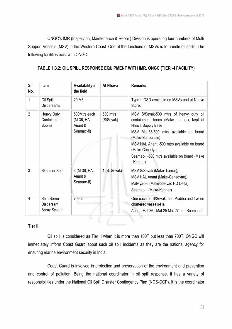
ONGC‟s IMR (Inspection, Maintenance & Repair) Division is operating four numbers of Multi
Support Vessels (MSV) in the Western Coast. One of the functions of MSVs is to handle oil spills. The
following facilities exist with ONGC.
TABLE 1.3.2: OIL SPILL RESPONSE EQUIPMENT WITH IMR, ONGC (TIER –I FACILITY)
Sl.
No.
Item Availability in
the field
At Nhava Remarks
1 Oil Spill
Dispersants
20 M3 Type-II OSD available on MSVs and at Nhava
Store.
2 Heavy Duty
Containment
Booms
500Mtrs each
(M-36, HAL
Anant &
Seamac-II)
500 mtrs
(S/Sevak)
MSV S/Sevak-500 mtrs of heavy duty oil
containment boom (Make -Lamor), kept at
Nhava Supply Base
MSV Mal-36-500 mtrs available on board
(Make-Seacurtain)
MSV HAL Anant -500 mtrs available on board
(Make-Canadyne).
Seamac-II-500 mtrs available on board (Make
–Kepner)
3 Skimmer Sets 3 (M-36, HAL
Anant &
Searnac-II)
1 (S. Sevak) MSV S/Sevak (Make- Lamor),
MSV HAL Anant (Make-Canadyne),
Malviya-36 (Make-Seavac HD Delta),
Seamac-II (Make-Kepner)
4 Ship Borne
Dispersant
Spray System
7 sets One each on S/Sevak, and Prabha and five on
chartered vessels-Hal
Anant, Mal-36., Mal-25 Mal-27 and Seamac-II
Tier II:
Oil spill is considered as Tier II when it is more than 100T but less than 700T. ONGC will
immediately inform Coast Guard about such oil spill incidents as they are the national agency for
ensuring marine environment security in India.
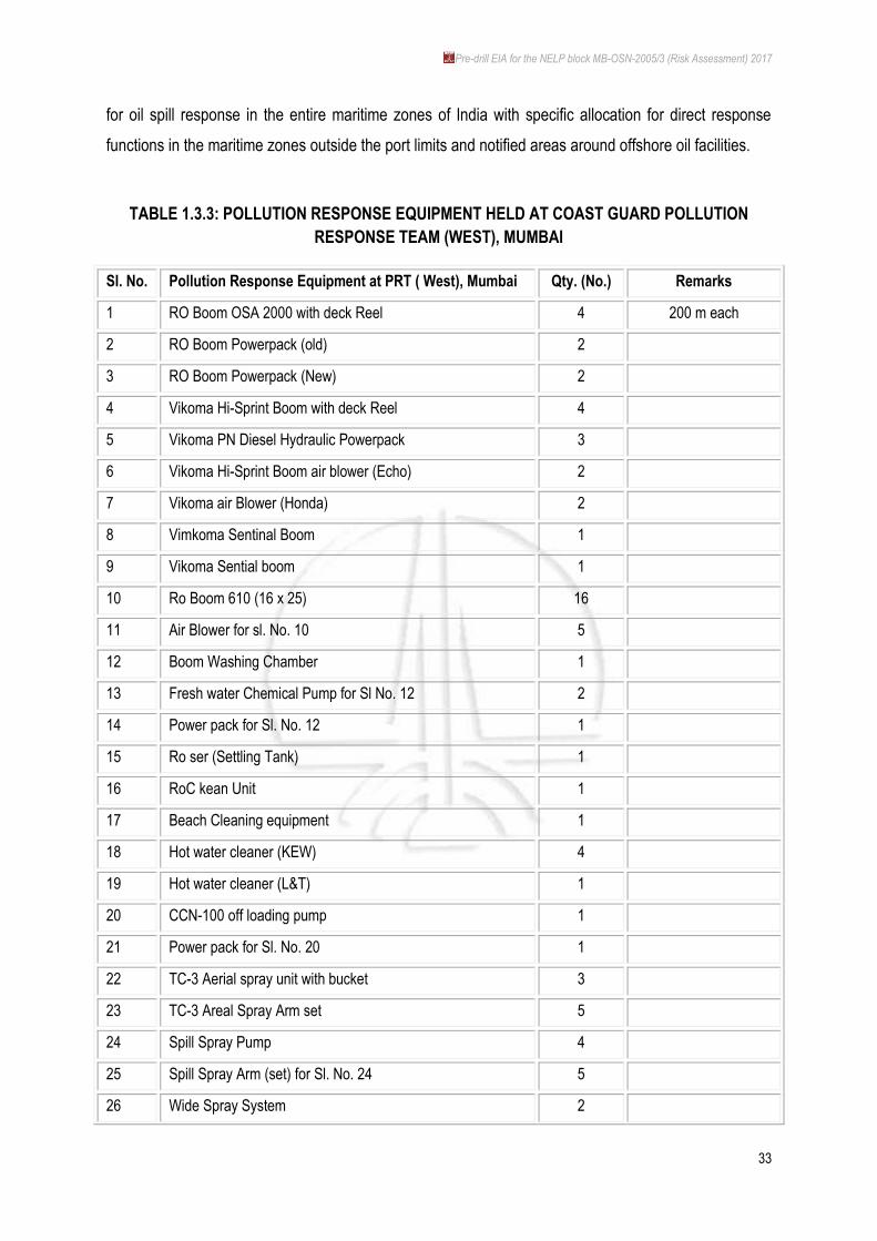
Coast Guard is involved in protection and preservation of the environment and prevention
and control of pollution. Being the national coordinator in oil spill response, it has a variety of
responsibilities under the National Oil Spill Disaster Contingency Plan (NOS-DCP). It is the coordinator
Pre-drill EIA for the NELP block MB-OSN-2005/3 (Risk Assessment) 2017
33
for oil spill response in the entire maritime zones of India with specific allocation for direct response
functions in the maritime zones outside the port limits and notified areas around offshore oil facilities.
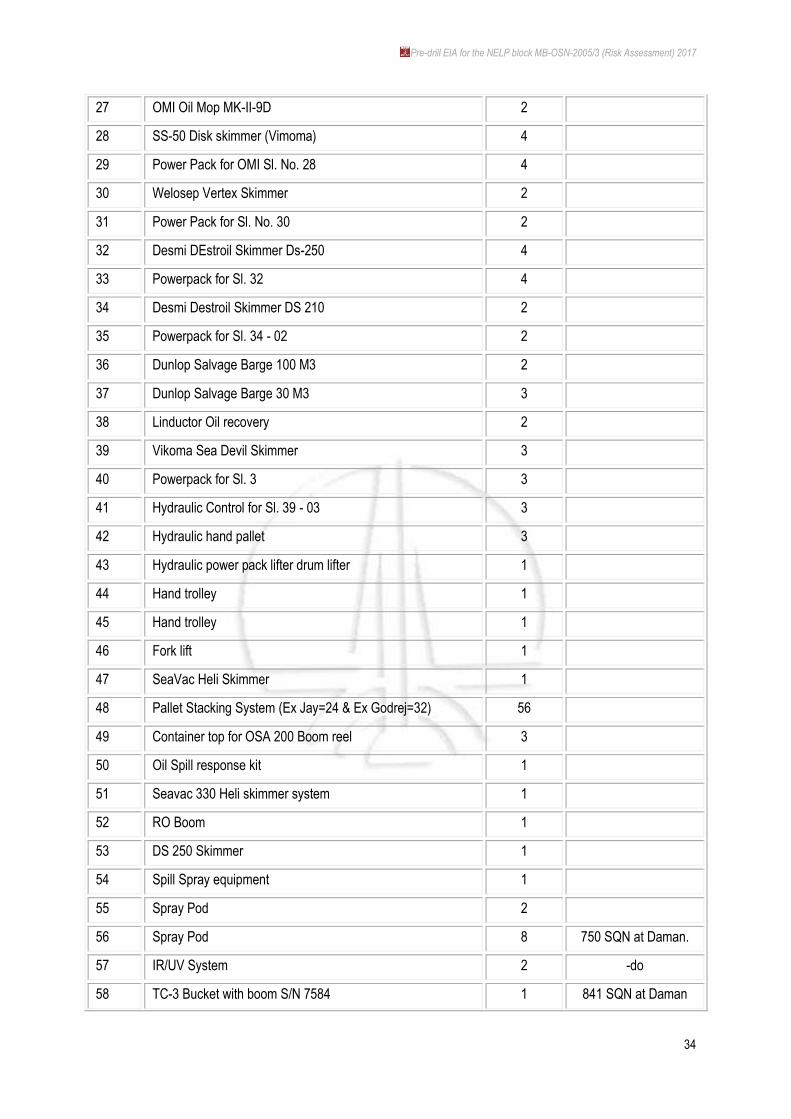
TABLE 1.3.3: POLLUTION RESPONSE EQUIPMENT HELD AT COAST GUARD POLLUTION
RESPONSE TEAM (WEST), MUMBAI
Sl. No. Pollution Response Equipment at PRT ( West), Mumbai Qty. (No.) Remarks
1 RO Boom OSA 2000 with deck Reel 4 200 m each
2 RO Boom Powerpack (old) 2
3 RO Boom Powerpack (New) 2
4 Vikoma Hi-Sprint Boom with deck Reel 4
5 Vikoma PN Diesel Hydraulic Powerpack 3
6 Vikoma Hi-Sprint Boom air blower (Echo) 2
7 Vikoma air Blower (Honda) 2
8 Vimkoma Sentinal Boom 1
9 Vikoma Sential boom 1
10 Ro Boom 610 (16 x 25) 16
11 Air Blower for sl. No. 10 5
12 Boom Washing Chamber 1
13 Fresh water Chemical Pump for Sl No. 12 2
14 Power pack for Sl. No. 12 1
15 Ro ser (Settling Tank) 1
16 RoC kean Unit 1
17 Beach Cleaning equipment 1
18 Hot water cleaner (KEW) 4
19 Hot water cleaner (L&T) 1
20 CCN-100 off loading pump 1
21 Power pack for Sl. No. 20 1
22 TC-3 Aerial spray unit with bucket 3
23 TC-3 Areal Spray Arm set 5
24 Spill Spray Pump 4
25 Spill Spray Arm (set) for Sl. No. 24 5
26 Wide Spray System 2
Pre-drill EIA for the NELP block MB-OSN-2005/3 (Risk Assessment) 2017
34
27 OMI Oil Mop MK-II-9D 2
28 SS-50 Disk skimmer (Vimoma) 4
29 Power Pack for OMI Sl. No. 28 4
30 Welosep Vertex Skimmer 2
31 Power Pack for Sl. No. 30 2
32 Desmi DEstroil Skimmer Ds-250 4
33 Powerpack for Sl. 32 4
34 Desmi Destroil Skimmer DS 210 2
35 Powerpack for Sl. 34 - 02 2
36 Dunlop Salvage Barge 100 M3 2
37 Dunlop Salvage Barge 30 M3 3
38 Linductor Oil recovery 2
39 Vikoma Sea Devil Skimmer 3
40 Powerpack for Sl. 3 3
41 Hydraulic Control for Sl. 39 - 03 3
42 Hydraulic hand pallet 3
43 Hydraulic power pack lifter drum lifter 1
44 Hand trolley 1
45 Hand trolley 1
46 Fork lift 1
47 SeaVac Heli Skimmer 1
48 Pallet Stacking System (Ex Jay=24 & Ex Godrej=32) 56
49 Container top for OSA 200 Boom reel 3
50 Oil Spill response kit 1
51 Seavac 330 Heli skimmer system 1
52 RO Boom 1
53 DS 250 Skimmer 1
54 Spill Spray equipment 1
55 Spray Pod 2
56 Spray Pod 8 750 SQN at Daman.
57 IR/UV System 2 -do
58 TC-3 Bucket with boom S/N 7584 1 841 SQN at Daman
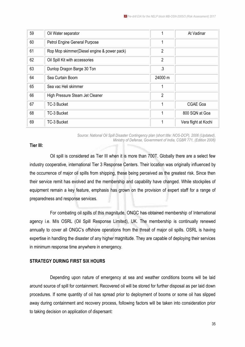
Pre-drill EIA for the NELP block MB-OSN-2005/3 (Risk Assessment) 2017
35
59 Oil Water separator 1 At Vadinar
60 Petrol Engine General Purpose 1
61 Rop Mop skimmer(Diesel engine & power pack) 2
62 Oil Spill Kit with accessories 2
63 Dunlop Dragon Barge 30 Ton .3
64 Sea Curtain Boom 24000 m
65 Sea vac Heli skimmer 1
66 High Pressure Steam Jet Cleaner 2
67 TC-3 Bucket 1 CGAE Goa
68 TC-3 Bucket 1 800 SQN at Goa
69 TC-3 Bucket 1 Vera flight at Kochi
Source: National Oil Spill Disaster Contingency plan (short title: NOS-DCP), 2006 (Updated),
Ministry of Defense, Government of India, CGBR 771, (Edition 2006)
Tier III:
Oil spill is considered as Tier III when it is more than 700T. Globally there are a select few
industry cooperative, international Tier 3 Response Centers. Their location was originally influenced by
the occurrence of major oil spills from shipping, these being perceived as the greatest risk. Since then
their service remit has evolved and the membership and capability have changed. While stockpiles of
equipment remain a key feature, emphasis has grown on the provision of expert staff for a range of
preparedness and response services.
For combating oil spills of this magnitude, ONGC has obtained membership of International
agency i.e. M/s OSRL (Oil Spill Response Limited), UK. The membership is continually renewed
annually to cover all ONGC‟s offshore operations from the threat of major oil spills. OSRL is having
expertise in handling the disaster of any higher magnitude. They are capable of deploying their services
in minimum response time anywhere in emergency.
STRATEGY DURING FIRST SIX HOURS
Depending upon nature of emergency at sea and weather conditions booms will be laid
around source of spill for containment. Recovered oil will be stored for further disposal as per laid down
procedures. If some quantity of oil has spread prior to deployment of booms or some oil has slipped
away during containment and recovery process, following factors will be taken into consideration prior
to taking decision on application of dispersant:
Pre-drill EIA for the NELP block MB-OSN-2005/3 (Risk Assessment) 2017
36
Spilled oil shall not be more than 4 hours old
Oil is moving towards shoreline
Spilled crude characteristics are amenable to use of dispersants
Prevailing weather conditions are conducive to dispersant applications.
Prior approval from Coast Guard for use of dispersant will be obtained.
Spraying of Dispersants
During rough weather, monsoon, low visibility or in case of delayed deployment of
equipment, the spraying of dispersants is considered one of the options, because this strategy needs
very less reaction time (resource mobilization time) and can be initiated by the boat/vessels crew
operating in the area. Spray of dispersants can be done through Helicopters also.
Response equipment such as Containment Booms will be deployed for protection of
Maharashtra coastal belt, the creeks and mangroves along the Maharashtra coast, and sensitive pilgrim
/ tourist area of Dwarka and Bet Dwarka, to deflect spills towards other areas of the shoreline where it
shall cause less harm to the environment.
Shore Cleanup
Despite best efforts to contain and recover spilled oil, there is always a likelihood of spilled
oil reaching shorelines. Shoreline cleanup technique will be practiced for the left over oil as per
topography of the coastline.
1.3.1.4 PROJECT NEED & BENEFITS
The hydrocarbons sector plays vital role in the economic growth of the country. Oil and gas
continue to play a pre-eminent role in meeting a part of the energy demands of the country. Growth of
the economy would lead to spontaneous growth in energy consumption. Economists opine that there
the GDP and per capita energy consumption is a directly proportional. The hydrocarbon sector,
therefor, plays a crucial role in the energy security for the country.
As per the Hydrocarbons Vision – 2025 of the Ministry of Petroleum & Natural Gas, Govt. of
India, inter alia, is – „to assure energy security by achieving self-reliance through increased indigenous
production and investment in equity oil abroad.‟ The medium term objective for E & P Sector of the
country includes:
Continue exploration in producing basins.

Pre-drill EIA for the NELP block MB-OSN-2005/3 (Risk Assessment) 2017
37
Aggressively pursue extensive exploration in non-producing and frontier basins for
knowledge building' and new discoveries.
Venturing into deep-sea offshore areas of the Indian basin for newer finds.
The rapid economic growth of the country and rising population result in the considerable
increase in demand of petroleum products. The gap between supply and availability of crude oil,
petroleum products as well as gas from indigenous sources is likely to increase over the years.
The growing demand and supply gap would require increasing emphasis on E&P sector to
pace keep with demand-supply relationships.
At present, India meets about 30% of petroleum requirements from all of its resources. It is,
therefore, impertinent to expedite exploration activities to minimize our dependence on the imports and
to ensure the energy security of our country.
In view of the unfavorable demand-supply balance of hydrocarbons in the country, ONGC
has been intensifying its E&P activities in Indian basins to improve on the domestic productivity of oil
and gas as well as make equity oil available by acquiring gas assets overseas with a focus on oil
security.
The Western Offshore area has been the main contributor of domestic hydrocarbon
production the Indian exchequer. The recent finds and discoveries have given new vistas and the
likelihood of finding potential hydrocarbon pools is quite high here in the basin.
Block MB-OSN-2005/3 is located in the Western Offshore basin and is proposed by ONGC
for exploratory drilling to explore for the liquid gold. In view of prognosticating the feasibility of presence
as well as tapping hydrocarbon, this offshore exploratory project is of immense domestic and national
importance.