10in. table saw - northern tool · 10in. table saw owner’s manual warning: read carefully and...
TRANSCRIPT

10IN. TABLE SAW
OWNER’S MANUAL
WARNING: Read carefully and understand all ASSEMBLY AND OPERATION INSTRUCTIONS before operating. Failure to follow the safety rules and other basic safety precautions may result in serious personal injury.
Item# 45988

Page of 30
2
Thank you very much for choosing an Ironton product! For future reference, please complete the owner’s record below: Model: _______________ Purchase Date: _______________ Save the receipt, warranty and these instructions. It is important that you read the entire manual to become familiar with this product before you begin using it. This machine is designed for certain applications only. The distributor cannot be responsible for issues arising from modification. We strongly recommend this machine not be modified and/or used for any application other than that for which it was designed. If you have any questions relative to a particular application, DO NOT use the machine until you have first contacted the distributor to determine if it can or should be performed on the product. For technical questions please call 1-800-222-5381.
INTENDED USE The Ironton Table Saw has been designed to cut timber and timber products. The large work table with easy to install side tables provide greater stability when cutting larger workpieces. Designed for multi-purpose applications such as ripping and crosscuts of timber, chipboard and plywood. The saw can be tilted up to 45º for miter cuts. Stand with anti slip rubber feet provides full support and stability. Wheels on the stand make it easy to maneuver and transport.
TECHNICAL SPECIFICATIONS Capacity with 10 in. Blade:
Depth of cut at 90° 3-1/8 in. Maximum tilt angle of arbor (left) 45° Depth of cut at 45° 2-5/32 in. Max. cut right of blade with rip fence 24-1/2 in.
Saw Dimensions:
Cabinet depth 11-13/32 in. Cabinet width 20-3/4 in. Cabinet length 25-15/32 in. Main table 24 x 21-1/16 in. Right extension table 5-63/64 x 21-1/16 in. Rear extension table 24 x 2-35/64 in. Saw blade: Blade max. capacity 10 in. Blade arbor 5/8 in. Saw Constructions: Cabinet Plastic Table Cast aluminum Rip fence Aluminum extrusion Drive system By gear Miter gauge Cast aluminum with T-slot roller guide Blade guard Acrylic with anti-kickback pawls Motor 120 V, 15 A, 60 Hz No load speed 4500 RPM Net weight 81.4 lbs

Page of 30
3
GENERAL SAFETY RULES
WARNING: Read and understand all instructions. Failure to follow all instructions listed below may result in serious injury.
CAUTION: Do not allow persons to operate or assemble this Table Saw until they have read this manual and have developed a thorough understanding of how the Table Saw works.
WARNING: The warnings, cautions, and instructions discussed in this instruction manual cannot cover all possible conditions or situations that could occur. It must be understood by the operator that common sense and caution are factors that cannot be built into this product, but must be supplied by the operator.
SAVE THESE INSTRUCTIONS
IMPORTANT SAFETY CONSIDERATIONS 1) Work area safety a) Keep work area clean and well lit. Cluttered or dark areas invite accidents. b) Do not operate power tools in explosive atmospheres, such as in the presence of flammable liquids, gases or dust. Power tools create sparks which may ignite the dust or fumes. c) Keep children and bystanders away while operating a power tool. Distractions can cause you to lose control. 2) Electrical safety a) Power tool plugs must match the outlet. Never modify the plug in any way. Do not use any adapter plugs with earthed (grounded) power tools. Unmodified plugs and matching outlets will reduce risk of electric shock. b) Avoid body contact with earthed or grounded surfaces, such as pipes, radiators, ranges and refrigerators. There is an increased risk of electric shock if your body is earthed or grounded. c) Do not expose power tools to rain or wet conditions. Water entering a power tool will increase the risk of electric shock. d) Do not abuse the cord. Never use the cord for carrying, pulling or unplugging the power tool. Keep cord away from heat, oil, sharp edges or moving parts. Damaged or entangled cords increase the risk of electric shock. e) When operating a power tool outdoors, use an extension cord suitable for outdoor use. Use of a cord suitable for outdoor use reduces the risk of electric shock. f) If operating a power tool in a damp location is unavoidable, use a residual current device (RCD) protected supply. Use of an RCD reduces the risk of electric shock.

Page of 30
4
3) Personal safety a) Stay alert, watch what you are doing and use common sense when operating a power tool. Do not use a power tool while you are tired or under the influence of drugs, alcohol or medication. A moment of inattention while operating power tools may result in serious personal injury. b) Use personal protective equipment. Always wear eye protection. Protective equipment such as dust mask, non-skid safety shoes, hard hat, or hearing protection used for appropriate conditions will reduce personal injuries. c) Prevent unintentional starting. Ensure the switch is in the off-position before connecting to power source and/or battery pack, picking up or carrying the tool. Carrying power tools with your finger on the switch or energizing power tools that have the switch on invites accidents. d) Remove any adjusting key or wrench before turning the power tool on. A wrench or a key left attached to a rotating part of the power tool may result in personal injury. e) Do not overreach. Keep proper footing and balance at all times. This enables better control of the power tool in unexpected situations. f) Dress properly. Do not wear loose clothing or jewelry. Keep your hair, clothing and gloves away from moving parts. Loose clothes, jewelry or long hair can be caught in moving parts. g) If devices are provided for the connection of dust extraction and collection facilities, ensure these are connected and properly used. Use of dust collection can reduce dust-related hazards. 4) Power tool use and care a) Do not force the power tool. Use the correct power tool for your application. The correct power tool will do the job better and safer at the rate for which it was designed. b) Do not use the power tool if the switch does not turn it on and off. Any power tool that cannot be controlled with the switch is dangerous and must be repaired. c) Disconnect the plug from the power source and/or the battery pack from the power tool before making any adjustments, changing accessories, or storing power tools. Such preventive safety measures reduce the risk of starting the power tool accidentally. d) Keep cutting tools sharp and clean. Properly maintained cutting tools with sharp cutting edges are less likely to bind and are easier to control. e) Use the power tool, accessories and tool bits etc. in accordance with these instructions, taking into account the working conditions and the work to be performed. Use of the power tool for operations different from those intended could result in a hazardous situation. 5) Service a) Have your power tool serviced by a qualified repair person using only identical replacement parts. This will ensure that the safety of the power tool is maintained. b) If the supply cord is damaged, it must be replaced by the manufacturer, its service agent or similarly qualified persons in order to avoid a hazard.

Page of 30
5
TABLE SAW USE AND CARE • Do not modify the Table Saw in any way. Unauthorized modification may impair the function
and/or safety and could affect the life of the equipment. There are specific applications for which the Table Saw was designed.
• Always check of damaged or worn out parts before using the Table Saw. Broken parts will affect the Table Saw operation. Replace or repair damaged or worn parts immediately.
• Store idle Table Saw. When Table Saw is not in use, store it in a secure place out of the reach of children. Inspect it for good working condition prior to storage and before re-use.
• No other people are allowed to stand in the direct vicinity of the machine when it is in use.
People not operating the machine must maintain a suitable safe distance. • Never lay the power cable over the saw table. • Use the push rod to pass the workpiece safely into the saw blade. Do not come too close to the
saw blade. • Make sure that the thickness of the material to be cut is less than the maximum possible cutting
depth. • Never cut “handsfree.” The workpiece must always lie level on the machine table and be
moved along the stop! The workpiece must always be pressed hard against the stop. • Never cut workpieces that are so small that they cannot be safety pressed against the stop and
could turn. • Never cut workpieces that are so small that they cannot be moved by the push rod at a safe
distance from the saw blade. • Only cut one workpiece at a time. Never cut several workpieces simultaneously. Workpiece
must not be placed behind or on top of each other. There is a danger of the workpiece “jamming” and slipping away.
• Make sure that the workpiece cannot slip while cutting or get jammed in the saw blade. • Clean the working area and the workpiece after each cut.
WARNING: Switch the tool off, remove the plug from the power socket and let the machine come to a standstill. No foreign bodies are allowed to be on the workpiece or the machine table. Cut pieces of the workpiece can be caught by the rotating cutting disc and be flung away. • Never reach into the openings of the table saw. Never insert objects into the openings of the
tool (e.g. the saw blade casing, dust extraction adaptor). Danger of cuts. • Never remove the cutting piece if the machine is still switched on or running. Danger of cutting
yourself. • Cut workpieces may have sharp edges, ridges or wooden splinters. Danger of cutting injuries. • Always switch the machine off and remove the power plug when your leave the machine. • Never expose the tool to rain or extreme moisture. • Do not perform any cuts with this table saw, other than those described in these operating
instructions. Do not saw seams and notches. • This table saw cannot to be used for slitting (notches which end in the workpiece).

Page of 30
6
ASSEMBLY
UNPACKING Refer to Figure A-B. 1. Carefully remove the table saw from the carton. 2. Separate the parts. 3. Lay out the parts, and check them against the parts listed below. Examine the parts carefully. A. Table saw parts
1 Riving knife 2 Table insert 3 Blade guard 4 Miter gauge 5 Working table 6 ON/OFF switch with key 7 Mounting holes 8 Rip fence 9 Right extension table 10 Blade bevel lock knob 11 Blade tilt/elevation
handwheel 12 Kickback pawls 13 Rear table 14 Blade wrench 15 Push stick 16 Blade 17 Overload reset switch 18 Stand 19 Wheel 20 Handle 21 Release lever 22 Leveling foot
Page of 30
7
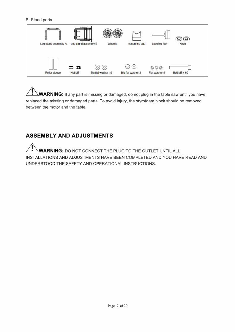
B. Stand parts
WARNING: If any part is missing or damaged, do not plug in the table saw until you have replaced the missing or damaged parts. To avoid injury, the styrofoam block should be removed between the motor and the table.
ASSEMBLY AND ADJUSTMENTS
WARNING: DO NOT CONNECT THE PLUG TO THE OUTLET UNTIL ALL INSTALLATIONS AND ADJUSTMENTS HAVE BEEN COMPLETED AND YOU HAVE READ AND UNDERSTOOD THE SAFETY AND OPERATIONAL INSTRUCTIONS.

Page of 30
8
ASSEMBLE THE STAND (fig. 1-6) • Unpack all of the parts, and group them by type and size. Refer to the parts list for correct quantities. (See Fig. 1) • Attach the tubes of the stand assembly (B) with the corresponding tubes of the stand assembly (A) and align the holes. (See Fig. 2) • Place the flat washer M8 (M), leveling foot (K) before insert the bolt M8 x 60 (L) into hole and put the flat washer M8 (M) on the opposite to the tube, then tighten the knob (F) with hex key tightening the bolt (L). (See Fig. 3) • Insert the bolt with leveling foot (D) into hole, and put flat washer M8 (M) on the opposite tube, then tighten the knob (F), and you can See Fig. 4.

Page of 30
9
• Slide the flat washer M10 (G), roller sleeves (E), wheels (C), and flat washer M8 (H) and nut M8 (J) onto the axle through the hole in the center of the wheel as illustrated. Secure in place using the wrench. (See Fig. 5) • Repeat with the second wheel. Fig. 6 shows completed stand assembly. NOTE: Verity that the stand is securely locked in an open position and that the shock adoption pad stabilized the table saw before operation. ATTACH THE TABLE SAW TO THE STAND (Fig. 7)
WARNING: DO NOT OPERATE THIS MACHINE ON THE FLOOR. THIS IS A VERY DANGEROUS POSITION. • Place the stand on a level surface and level the stand to the floor. • Place the table saw on top of the stand, aligning the holes in the base with the holes in the stand. • Place the flat washer before insert four hex bolts through the holes in the base and the stand. • Tighten all four bolts with hex key. NOTE: DO NOT OVER-TIGHTEN THE NUTS THAT HOLD THE SAW TO THE STAND. DOING SO WILL DAMAGE THE SAW BASE. TO SECURE/LEVEL THE TABLE SAW (Fig. 8) With the stand open and the table saw resting on a flat, level surface, the table saw should not move or rock from side to side. If the table saw rocks from side to side, the leveling foot needs adjusting until the stand is balanced. • Loosen the knob counterclockwise. • Lift the table saw slightly so that you may turn the leveling foot until the stand no longer rocks. • Turning clockwise will lower the foot. • Turning counterclockwise will raise the foot. NOTE: Only the leveling foot with nut can be adjusted

Page of 30
10
for height. TO OPEN THE LEG STAND (Fig. 9-11) • Grasp the grips on the stand and stand the table saw upright as shown Fig. 9. • Step on the leaser lever and pull the grips toward you at the same time. • Step on the leaser lever and pull the grips toward you at the same time. • Once the stand is released from the release lever, slide stand toward the floor by pushing the grips toward the floor.(Fig. 10) • With your hands on the grips, push the stand towards the ground until the table saw is in an open position. (Fig. 11) NOTE: The release lever will close over the center brace locking the stand in an open position. (Fig. 11) TO STORE THE TABLE SAW ACCESSORIES The table saw has convenient storage areas (lie in the table saw cabinet) specifically designed for the saw’s accessories. These accessories must be securely stored prior to closing the stand and moving the saw.

Page of 30
11
TO CLOSE THE LEG STAND AND MOVE THE SAW (Fig. 12-15) • Remove any workpieces from the tool. • Remove and securely store any tools or accessories such as rip fence, miter gauge blade guard, push stick, etc. • Lower the saw blade. To close the leg stand: • At the same time, step on the release lever, grasp the grips, and lift the handles up and away from the body. • Push the table saw until the release lever clicks and locks into place. (Fig. 12-13) To move the leg stand: • Holding the grips firmly, pull the handles towards you until the stand and saw are balanced on the wheels. • Push the table saw to the desired location then either open the stand for saw operation or store the table saw in a dry environment. (Fig. 14-15)

Page of 30
12
MOUNTING THE TABLE SAW TO A WORKBENCH (FIG.16-17) • Step.1: If the stand will not be used, the table saw must be properly secured to a sturdy workbench using the four mounting holes on the base. • Step.2: The workbench must have a hole that is large enough to allow for sawdust fall through and removal. • Step.3: Place the table saw in the center of the workbench tabletop, and mark the location of the four mounting holes (1) on the workbench tabletop. • Step.4: Drill four holes in the workbench tabletop. NOTE: If there is not a hole that is large enough for sawdust removal and fall-through, proceed to step 5. If there is a hole that is large enough, proceed to step 7. • Step.5: Mark a 11 x 11in. square (2), centered between the four mounting holes (1). • Step.6: Cut out and remove the square. This opening will allow sawdust to fall through the saw base. • Step.7: Place the table saw on the workbench tabletop, and align the holes of the table saw with the holes that were drilled in the workbench tabletop. Fasten the table saw to the workbench using 3/8” bolts and nuts. NOTE: bolts and nuts are not included. IMPORTANT: When mounting the saw to the stand or workbench DO NOT over tighten the mounting bolts. NOTE: If the stand or the workbench tends to move while the table saw is in use, the stand or workbench must be fastened to the floor.
WARNING: Failure to provide the sawdust fall-through and removal hole will cause sawdust to build up in the motor area, which may result in a fire hazard or cause damage to the motor. KEEPING THE AREA CLEAN
WARNING: ALWAYS KEEP YOUR WORK AREA CLEAN, UNCLUTTERED, AND WELL LIT. DO NOT WORK ON FLOOR SURFACES THAT ARE SLIPPERY FROM SAWDUST OR WAX. Sawdust and wood chips that fall under the saw will accumulate on the floor. Make it a practice to pick up and discard this dust when you have completed cutting. BLADE RISING/TILTING HANDWHEEL (FIG. 18) • Rotate the crank handle (1) clockwise to raise the blade, and anti-clockwise to bring down the blade. • Rotate the handwheel (2) clockwise, and move along the arc rail, then the blade will tilt from 0° to 45°, or rotate counterclockwise. • Secure the blade bevel lock knob (3) when the bevel angle pointer (4) points at desired angle on scale

Page of 30
13
TO REMOVE/REPLACE/ALIGN THE TABLE INSERT (Fig. 19)
WARNING: The table insert must be level with the saw table. If the table insert is too high or too low, the workpiece can catch on the uneven edges resulting in binding or kickback which could result in serious personal injury. Loosen the handle as shown to remove the blade guard from the riving knife (Fig. 20)
WARNING: To avoid injury, ensure the switch is on the off position and the saw is unplugged before removing the blade guard. Lower the blade by: 1) Unlock the blade height lock knob (turn counterclockwise). 2) Turn the height adjusting knob counterclockwise to lower the blade. • To remove the table insert: place your index in the hole and lift the front end pulling the table insert out toward the front of the saw. • To reinstall the table insert: slip the tab into the slot at the back of the saw and push down to secure in place. Using a hex key, adjust the six set screws until the table insert is level with the saw blade. INSTALL THE BLADE TO THE ARBOR (Fig. 21-23)
WARNING: TO AVOID INJURY FROM AN ACCIDENTAL STARTUP, VERIFY THAT THE SWITCH IS IN THE “OFF” POSITION AND THE PLUG IS NOT CONNECTED TO THE OUTLET. IN ORDER TO AVOID SERIOUS INJURY, THE TABLE INSERT MUST BE LEVEL WITH THE TABLE. NOTE: KEEP THIS MANUAL AS REFERENCE FOR FUTURE BLADE CHANGES. • Remove the table insert (1) by inserting the finger into the hole (2) (see Fig. 21). • Raise the saw blade arbor (3) to its maximum height by turning the blade raising hand wheel counter-clockwise. Remove the arbor nut (4) and the outer flange (5) from the saw arbor. (see Fig. 22) • Place the saw blade on the arbor, making sure the teeth of the blade point DOWN at the front of the table. • Place the flange (5) and the arbor nut (4) on the arbor, and tighten the nut as far as possible by hand, making sure the saw blade is firmly seated against the inner flange (6) (see Fig. 21). NOTE: Make sure the large flat surfaces of the flange and the nut face INWARD, toward the saw blade.

Page of 30
14
• Place the jaws of the open-ended wrench (7) on the flats of the flange (5) in order to prevent the arbor from turning while tightening. Tighten the arbor nut by turning it clockwise using the open-ended wrench (7) (See Fig. 23).
WARNING: MAKE SURE THE SAW BLADE, ARBOR FLANGE, AND NUT ARE PROPERLY SEATED, AND VERIFY THAT THE ARBOR NUT IS TIGHT. ADJUSTING THE RIVING KNIFE (Fig. 24-26) This saw is shipped with the riving knife placed in “down” position. NOTE: The riving knife has two positions: 1) midpoint when not fully cutting through wood e.g. making channels; 2) fully up for normal operation. • Unplug the saw. To place in “up” position for all through cutting: • Remove the table insert. • Raise the saw blade by turning the height adjusting knob clockwise. • Unlock the release lever by pushing the lever up. (see Fig. 24) • Grasp the riving knife and push it towards the right to unlock it from the pin then pull it up until the pins are reengaged and the riving knife is “up” position. (see Fig. 25) • Lock the release lever by pushing the lever down. (see Fig. 24) • Reinstall the table insert. To place in mid-point for non-through cutting e.g. making channel: • Remove the table insert. • Raise the saw blade by turning the height adjusting knob clockwise. • Unlock the release lever by pushing the lever up. • Grasp the riving knife and push it towards the right to unlock it from the pin then pull it down until it is located in the mid-point position. (see Fig. 26) • Lock the release lever by pushing the lever down. • Reinstall the table insert.

Page of 30
15
TO INSTALL THE ANTI-KICKBACK PAWLS AND BLADE GUARD (FIG.27-30) NOTE: Anti-kickback pawls should only be installed for through cuts. • Unplug the saw. • Raise the saw blade. • Place the riving knife in “up” position. TO INSTALL ANTI-KICKBACK PAWLS: • Installing the anti-kickback pawls on the riving knife as shown (Fig. 27-a), the pin on the anti-kickback pawls is inserted in the slot of riving knife. • Lock the handle as shown in the (Fig. 27-b) TO INSTALL BLADE GUARD: • Installing the blade guard on the riving knife as shown (Fig. 28-a), the pin on the blade guard base should match with the slot on the riving knife as shown (Fig. 28-b). • Then tightening the handle as shown (Fig. 29), the blade guard should be parallel with the worktable (Fig. 30). If the blade guard is not parallel, the riving knife is not in “up” position.
WARNING: Do not operate saw without blade guard in place.

Page of 30
16
CHECK AND ALIGN THE RIVING KNIFE AND SAW BLADE (FIG.31-32) If the riving knife is out of alignment with the saw blade, adjustment is needed. • Unplug the saw. • Raise the saw blade by turning the height adjusting knob clockwise. • Remove the anti-kickback pawls and blade guard assembly. Place a framing square or straight edge against both the saw blade and the riving knife. (see Fig. 31) NOTE: Place framing square between carbide teeth and measure from blade. This step will insure framing square is square against blade from the front to back of blade. • The saw blade and riving knife are aligned when the framing square contacts both the blade and splitter evenly with no gaps. TO ADJUST • Remove the anti-kickback pawls and blade guard assembly. • Loosen the screws holding the mounting bracket. (see Fig. 32) • Reposition the riving knife left or right as needed to align the riving knife with the saw blade. • Once properly aligned, securely retighten the screws. NOTE: The blade guard and riving knife must always be correctly aligned so that the cut workpiece will pass on either side of the splitter without binding or twisting to the side.
WARNING: Improper riving knife alignment can cause kickback and serious injury. ADJUSTING THE REAR TABLE EXTENSION • When ripping a short workpiece, the rear extension table should be positioned as close to the rear of the main table as possible. • When ripping a long workpiece that requires extra support as the cut is completed, the rear extension table should be pulled out as far as possible, until the locating seat prevents it from moving out any further.
CAUTION: PIECES OVER 24IN. SHOULD BE HELD BY TWO PERSONS OR ROLLER TO ACCEPT THE CUT PIECES. INSTALLING AND USING THE RIP FENCE (FIG.33-34) • The rip fence can be used on either side of the saw blade. • The fence (1) is moved by lifting the handle (2) and sliding the fence to the desired. • Position the fence on the right side of the table, along the edge of the miter gauge groove. • Lock the fence handle. The fence should be parallel with the miter gauge groove. • If adjustment is needed in order to make the fence parallel to the groove, follow these step: • Loosen the two bolts (3), and lift the handle (2). • Hold the fence bracket (4) firmly against the front of the saw blade. Move the far end of the fence until it is parallel with the miter gauge groove.

Page of 30
17
• Push the handle down to lock it, and tighten both screws. • If fence is loose when handle is in the lock (down) position, follow these steps: • Lift the handle (2) and turn the adjusting nut (5) clockwise until the rear clamp is snug. Do not turn the adjusting screw more than 1/4 turn at a time. • Over-tightening the adjusting screw could bend the rear clamping lever, which may cause the fence to come out of alignment. ADJUSTING THE RIP FENCE INDICATOR (FIG.35) • The rip fence indicator (6) points to the measurement scale (8). The scale shows the distance from the side of the fence closest to blade. • Measure the actual distance with a ruler. If there is a difference between the measurement and the indicator, adjust the indicator (6). • Loosen the screw (7), and slide the indicator to the correct measurement on the scale. Tighten the screw, and re-measure with ruler. ADJUSTING THE MITER GAUGE (FIG.36) • Loosen the lock handle (1) in order to allow the miter body (2) to rotate freely. Position the miter body at 90o, so that the positive detent secures its position. Tighten the lock handle in order to hold the miter body in position. • If the pointer (3) requires adjustment, loosen the two screws under the pointer using a hex wrench. Adjust the pointer to 90o on the scale, and then firmly tighten both adjusting screws. • To change angles on the miter gauge, loosen the lock handle (1) and rotate the miter body to the desire angle, as indicated by the scale. Secure in position by tightening the lock handle.
ADJUSTING THE 90º AND 45º POSITIVE STOPS (FIG. 37-38) This saw has positive stops that will quickly position the saw blade at 90° to the table. Make adjustments only if necessary. 90º STOP (FIG. 37) • Raise the blade to the maximum height by turning the control handle counter -clockwise. • Loosen the bevel angle locking knob. • Tilt the blade to the 90º(0º) bevel. • Using a square (1), verify that the blade is at a 90º(0º) angle to the table top. • If blade is not at a 90º(0º) angle to the table, loosen the adjustment screw (2). • Loosen the bevel locking knob and square the blade 90º(0º) to the table. • Once the blade is at a 90º(0º) angle to the table top, tighten the bevel angle locking knob. • Carefully tighten the adjusting screw (2) until it touches the bevel stop. DO NOT OVERTIGHTEN. • Verify that the blade is still aligned at 90º(0º).

Page of 30
18
45º STOP (FIG. 38) • Raise the blade to the maximum height by turning the control handle counter-clockwise. • Loosen the bevel angle locking knob. • Tilt the blade to the 45° bevel. • Using a square (1), verify that the blade is at a 45º angle to the table top. • If blade is not at a 45º angle to the table, loosen the adjustment screw (2). • Loosen the bevel locking knob and set the blade at a 45ºangle to the table. • Once the blade is at a 45ºangle to the table top, tighten the bevel angle locking knob. • Carefully tighten the adjusting screw (2) until it touches the bevel stop. DO NOT OVERTIGHTEN. • Verify that the blade is still aligned at 45º. BLADE TILT POINTER (FIG. 39) • When the blade is positioned at 90º, adjust the blade tilt pointer read 0º on the scale. • Loosen the holding screw, position the pointer over the 0º, and tighten the screw. NOTE: Make a trial cut on a scrap piece of wood before making critical cuts. Measure for exactness. CAUTION: TO PREVENT PERSONAL INJURY: a. ALWAYS DISCONNECT THE PLUG FROM THE POWER SOURCE WHEN MAKING ANY ADJUSTMENTS. b. THIS ADJUSTMENT MUST BE CORRECT, OR KICKBACK COULD RESULT IN A SERIOUS INJURY AND INABILITY TO MAKE ACCURATE CUTS.
OPERATION BASIC SAW OPERATIONS: RAISE THE BLADE (FIG. 40) In order to raise or lower the blade, turn the blade elevation handwheel (1) to the desired blade height and then tighten the lock knob (2) in order to maintain the desired blade angle. TILTING THE BLADE (FIG. 40) • In order to tilt the saw blade for bevel cutting, loosen the lock knob (2) and turn the blade tilt handwheel (3). • Tighten the lock knob (2) in order to secure the blade at the proper angle. ON/OFF SWITCH (FIG. 41) The ON/OFF switch has a removable key. With the key removed from the switch, the risk for unauthorized and hazardous use by children and others is minimized. • To turn the saw ON, insert the key (2) into the slot in the switch (1). Move the switch upward to the ON position. • To turn the saw OFF, move the switch downward. • To lock the switch in the OFF position, grasp the end (or yellow part) of the toggle switch (2) and pull it out. • The switch will not operate with the switch key removed.

Page of 30
19
• If the switch key is removed while the saw is running, it can be turned OFF, but it cannot be restarted without inserting the switch key (2). OVERLOAD PROTECTION (FIG. 41) This saw has a reset overload relay button (3) that will restart the motor after it shuts off due to overloading or low voltage. If the motor stops during operation, turn the ON/OFF switch to the OFF position. Wait approximately five minutes for the motor to cool off, and then push the reset button (3) and turn the switch to the ON position.
WARNING: In order to avoid injury, the on/off switch should be in the off position and the plug should be removed from the power source while the motor is cooling down. This will prevent accidental startup when the reset button is pushed. Overheating may be caused by misaligned parts or by a dull blade. Inspect the saw for proper setup before using it again.
TO USE THE SLIDING TABLE EXTENSION (FIG. 42) Increase the length of the saw table by using the sliding table extension. • Remove the rip fence. • Unlock the sliding table extension by lifting the table extension locking lever counter-clockwise. • Slide the table extension to the desired width. NOTE: Use the scale on the front rail when a specific width is desired. • Once the extension table is set to the desired width, relock the lever by pushing the lock lever back clockwise. BASIC OPERATION OF THE TABLE SAW (FIG. 43-45) CAUTION: READ GENERAL SAFETY GUIDELINES FOR THE TABLE SAW BEFORE OPERATING THIS SAW. YOUR SAFETY DEPENDS ON IT. VERIFY THE FOLLOWING EVERY TIME THE SAW IS USED: a. The blade is tight. b. The bevel angle locking knob is tight. c. If ripping, the fence locking knob is tight, and the fence is parallel, and the miter gauge knob is tight. d. If crosscutting, the miter gauge knob is tight. e. The blade guard and splitter are in place, and are working properly. f. Safety glasses are being worn. Failure to adhere to these safety rules can greatly increase the chances of injury. Before using the table saw, polish the table with an automotive wax in order to keep it clean and make it easier to slide the workpiece. There are two basic types of table saw cuts: ripping and crosscutting. In general, ripping means cutting with the grain, along the length of the workpiece. Crosscutting means either cutting across the width or across the grain of the workpiece. However, with man-made materials, this distinction can be difficult to make. Therefore, cutting a piece of wood to a different width is ripping, and cutting across the short dimension is crosscutting. Neither ripping nor crosscutting operations can be performed safely

Page of 30
20
freehand: ripping requires the use of the rip fence, and crosscutting requires the use of the miter gauge. RIPPING (FIG. 43-44)
WARNING: To prevent serious injury: a. Never use the miter gauge when ripping. b. Never use more than one rip fence during a single cut. c. Do not allow familiarity or frequent use of your table saw to cause careless mistakes. Remember that even a fraction of a second of carelessness is enough to cause a severe injury. d. Keep both hands away from the blade and the path of the blade. e. When ripping, the workpiece must have a straight edge against the fence, and must not be warped, twisted, or bowed. • Remove the miter gauge, and secure the rip fence to table. • Adjust the blade so that it is approximately 1/8in. higher than the workpiece. • Hold the workpiece flat on the table and against the fence. Keep the workpiece approximately 1 in. away from the blade. • Turn the saw ON, and allow the blade to come up to full speed. • Slowly feed the workpiece into the blade by pushing forward only on the section of the workpiece that will pass between the blade and the fence (see Fig. 43). • Keep your thumbs off the table top. When both of your thumbs touch the front edge of the table, complete the cut using a push stick. (see Fig. 44) • The push stick should always be used when the ripped workpiece is 2 in. wide or narrower.
• Continue to push the workpiece with the push stick until it passes the blade guard and clears the rear of the table. • Never pull the workpiece back while the blade is turning. Turn the switch OFF. When the blade comes to a complete stop, raise the anti-kickback pawls on either side of the splitter, if necessary, and then slide the workpiece out. CAUTION! Avoid kickback by pushing only on the section of workpiece that will pass between the blade and the fence. BEVEL RIPPING This operation is the same as ripping, except that the bevel angle is set to an angle other than 0º. CAUTION! Only cut with the workpiece and the fence on the right-hand side of the blade. RIPPING SMALL PIECES CAUTION! Avoid injury resulting from contact with the blade. Never make through-cuts narrower than 3/4in. wide. • It is not safe to rip small pieces. It is not safe to put your hands close to the blade. In order to ensure your safety, rip the small piece from a large piece. • When a small width is to be ripped and the hand cannot be safety put between the blade and the rip

Page of 30
21
fence, use one or more push sticks. Use the push sticks to hold the workpiece against the table top and the fence, and to push the workpiece completely past the blade (see Fig. 46) CROSSCUTTING (FIG. 45) CAUTION! To prevent serious injury: a. Do not allow familiarity or frequent use of your table saw to cause careless mistakes. Remember that even a fraction of a second of carelessness is enough to cause a severe injury. b. Keep both hands away from the blade and the path of the blade. c. Never attempt to pull the workpiece backward during a cutting operation. This will cause kickback, and serious injury to the user can occur. • Remove the rip fence, and place the miter gauge in one of the grooves on the table. • Adjust the blade height so that it is 1/8in. higher than the top of the workpiece. • Hold the workpiece firmly against the miter gauge, with the blade path in line with the desired cut location. Move the workpiece to within 1in. of the blade. • Start the saw, and wait for the blade (1) to come up to full speed. Never stand directly in line with the path of the saw blade. • Keep the workpiece (2) against the face of the miter gauge (3) and flat against the table. Slowly push the workpiece through the blade. • Do not attempt to pull the workpiece backward while the blade is turning. Turn the switch OFF, and wait until the blade has come to a complete stop before carefully sliding the workpiece out.
WARNING: In order to avoid instability, always place the larger surface of the workpiece on the table when crosscutting and/or bevel crosscutting. BEVEL CROSSCUTTING 0º~45ºBLADE BEVEL & 90O MITER ANGLE(FIG. 46) This cutting operating is the same as crosscutting, except that the blade is at a bevel angle other than 0º. This operation must be performed with miter gauge in the right side groove. • Adjust the blade (1) to the desired angle, and then tighten the blade bevel lock knob. • Tighten the miter lock handle (3) at 90º. • Hold the workpiece (2) firmly against the face of the miter gauge throughout the cutting operation.
WARNING: Always work to the right side of the blade during this type of cut. The miter gauge must be in the right side groove, because the bevel angle may cause the blade guard to interfere with the cut if it is used in the left side groove.

Page of 30
22
0º~45º BLADE BEVEL & 0º~45ºMITER ANGLE (FIG.47) This sawing operation combines a miter angle with a bevel angle. This operation must be performed with the miter gauge in the right side groove. • Set the miter gauge (3) to the desired angle. • Place the miter gauge in the right side groove of the table. • Set the blade (1) bevel to the desired bevel angle, and tighten the blade bevel lock knob. • Hold the workpiece (2) firmly against the face of the miter gauge throughout the cutting operation.
WARNING: Always work to the right side of the blade during this type of cut. The miter gauge must be in the right side groove, because the bevel angle may cause the blade guard to interfere with the cut if it is used in the left side groove. MITERING 0º~45º MITER ANGLE (FIG. 48) This sawing operation is the same as crosscutting, except that the miter gauge is locked at an angle other than 90º. • Set the blade (1) to the 0º bevel angle, and then tighten the blade bevel lock knob. • Set the miter gauge (3) to the desired miter angle, and lock it in position by tightening the miter gauge locking handle. • Hold the workpiece (2) firmly against the face of the miter gauge throughout the cutting operation.

Page of 30
23
Size: inch

Page of 30
24
MAINTENANCE • Maintain your Table Saw. It is recommended that the general condition of any Table Saw be
examined before it is used. Keep your Table Saw in good repair by adopting a program of conscientious repair and maintenance. Have necessary repairs made by qualified service personnel.
CAUTION! For your own safety, turn the switch OFF and remove the key. Remove the plug from the power source before maintaining or lubricating your saw. GENERAL MAINTENANCE Clean out all sawdust that has accumulated inside the saw base and around the motor. Polish the saw table with an automotive wax in order to keep it clean and to make it easier to slide the workpiece. Clean the cutting blades with pitch and gum remover. Immediately replace a worn, cut, or damaged power cord.
CAUTION! All electrical and mechanical repairs should be performed by a qualified repair technician. Use only identical replacement parts. Any substitute parts may create a hazard. Use liquid dish washing detergent and water to clean all plastic parts. NOTE: The use of certain cleaning chemicals may damage plastic parts. Do not use the following cleaning chemicals or solvents on your table saw: gasoline, carbon tetrachloride, chlorinated solvents, ammonia, and household detergents that contain ammonia. BLADE RAISING MECHANISM (FIG. 49) The blade raising mechanisms should be checked for looseness, binding, or other abnormalities after every five hours of operation. Disconnect the table saw from the power source and turn it upside down, and then alternately pull upward and downward on the motor on the motor unit. Observe any movement in the motor mounting mechanism. (See Fig. 49) • Turn the screw pole (1) in the fixed part (2) connection with the wheel. • The power will be transferred by the tapered gear (3) and screw pole (4). • The pole (6) in the fixed part (5) will be moved up and down. Place a small amount of dry lubricant, such as graphite or silicone, on the screw rod at the thrust washer. Do not oil the threads of the screw rod. For smooth operation, the screw rod must be kept clean and free of sawdust, gum, pitch, and other contaminants. Wet lubricants such as oil will attract sawdust, etc. If excessive looseness is observed in any other part of the blade raising or tilting mechanisms, please call 1-800-222-5381.
LUBRICATION All motor bearing are permanently lubricated at the factory, and do not require any additional lubrication. Lubricate all mechanical parts of your table saw where a pivot or threaded rod is present with graphite or silicone. These dry lubricants will not hold sawdust like oil or grease will.

Page of 30
25
TROUBLESHOOTING GUIDE
WARNING! To avoid injury from an accidental start-up, always turn switch OFF! And unplug the table saw before moving, replacing the blade or making adjustments. SYMPTOM POSSIBLE CAUSE(S) CORRECTIVE ACTION The saw will not start 1. The saw is not plugged in
2. The fuse has blown or the circuit breaker has tripped 3. The cord is damaged
1. Plug in the table saw 2. Replace the fuse of reset the circuit breaker 3. Have the cord replaced by a qualified electrician
The saw does not make accurate 45ºor 90º rip cuts
1. The positive stop is not adjusted correctly 2. The blade tilt pointer is not set correctly 3. The rip fence is not properly aligned
1. Check the blade with the square, and adjust the positive stop 2. Check the blade with the square, and adjust the pointer to zero 3. Align the rip fence with the miter gauge slot
The material pinches the blade when ripping
1. The rip fence is not aligned with the blade 2. The wood is warped, the edge against the fence is not straight
1. Check and adjust the rip fence 2. Select another piece of wood
The material binds on the splitter
1. The splitter is not aligned correctly with the blade
1. Check and align the splitter with the blade
The saw makes unsatisfactory cuts
1. The blade is dull 2. The blade is mounted backwards 3. There is gum or pitch on the blade 4. The blade is not appropriate for the work being done 5. There is gum or pitch on the table, causing erratic feeding
1. Replace the blade 2. Turn the blade around 3. Remove the blade and clean it with turpentine and coarse steel wool 4. Change the blade 5. Clean the table with turpentine and coarse steel wool, and apply a coat of automotive polishing wax
The material kicks back from the blade
1. The rip fence is out of alignment 2. The splitter is not aligned correctly with the blade 3. The workpiece is being fed without the rip fence 4. The splitter is not in place 5. The blade is dull 6. The operator is letting go of the material before it has passed the saw blade 7. The miter angle lock knob is loose
1. Align the rip fence with the miter gauge slot 2. Align the splitter with the blade 3. Install and use the rip fence 4. Install and use the splitter (with the guard) 5. Replace the blade 6. Push the material all the way past the saw blade before releasing the workpiece 7. Tighten the knob
The blade does not raise or tilt freely
1. There is sawdust and/or dirt in the raising and tilting mechanisms
1. Brush or blow out any loose dust and dirt
The blade does not come up to speed
1. The extension cord is too light or too long 2. The voltage from the power souce is too low
1. Replace with the proper size of extension cord 2. Contact your distributor.
The saw vibrates excessively
1. The saw is not mounted securely to the workbench 2. The bench is on an uneven surface 3. The blade is damaged
1. Tighten all mounting hardware 2. Reposition the table saw on a flat level surface 3. Replace the blade
The saw does not make accurate 45º or 90ºcrosscut
1. The miter gauge is out of adjustment
1. Adjust the miter gauge

Page of 30
26
DIAGRAM AND PARTS LIST

Page of 30
27
NO. Part Name QT NO. Part Name QT
1 Hex bolt M8 x 60 4 45 Junction box groupware 1 2 Flat washer 8 1 46 Switch board 1 3 Absorbing pad (B) 1 47 Flat washer 4 1 4 Stand E 2 48 Overloading protection label 1 5 Knob 2 49 Overloading protection nut 1 6 Hex bolt M8 x 70 2 50 Switch 1 7 Absorbing pad (A) 4 51 Reinforce side board 1 8 - - - 4 52 Bolt M5 x 8 1 9 Hex nut M8 6 53 Rack (B) 1 10 Absorbing pad (C) 1 54 Angle pointer 6 11 Locking nut M8 2 55 Bolt M5 x 16 6 12 Stand assembly (A) 2 56 Spring washer 4 2 13 Catch gauge (A) 1 57 Bolt M4 x 10 1 14 Spacer bush 8 58 Adjustment handle 1 15 Catch gauge (B) 1 59 Gasket ring 1 16 Spring 2 60 Hex nut M5 2 17 Sleeve for hook 1 61 Locking compress spring 1 18 Screw M6 x 45 2 62 Locking handle 1 19 Screw M6 x 50 1 63 Compaction screw 1 20 Screw M6 x 65 1 64 Adjustment handle 1 21 Shockinsulator (B) 1 65 Hex bolt M5 x 12 1 22 Stand assembly (C) 1 66 Circumgyrate Knob 1 23 Closing plate for stand 1 67 Bolt 1 24 Stand assembly (B) 2 68 Bolt M5 x 20 1 25 Screw M6 x 70 1 69 Spring washer 5 1 26 Screw M6 x 80 1 70 Flat washer 5 1 27 Big washer 10 1 71 Up-down column 1 28 Wheel 1 72 Prick gear 1 29 Sleeve for wheel 2 73 Ring for shaft 10 1 30 Big washer 8 1 74 Up-down adjustment seat 1 31 Shockinsulator (A) 1 75 Up-down adjustment screw (B) 15 32 Chassis assembly for stand 1 76 Down damper for body 1 33 Locking nut M5 1 77 Flat key 4 x 8 1 34 Sleeve for tube 1 78 Up-down adjustment screw (A) 1 35 Bolt M4 x 8 1 79 Bolt M6 x 16 1 36 Hex bolt M5 x 25 1 80 Spring washer 6 1 37 Handle assembly for stand 1 81 Flat washer 6 1 38 Main label 1 82 Fix seat (A) 1 39 Bolt ST2.9 x 9 2 83 Screw M6 x 16 1 40 Rubber ring (B) 5 84 Fix seat (B) 1 41 Bolt ST 4.2 x 12 4 85 Body 4 42 Switch box cover 10 86 Hex bolt M5 x 20 4 43 Handle 1 87 Damper for body 1 44 Overloading protection 1 88 Bolt M4 x 12 2

Page of 30
28
NO. Part Name QT NO. Part Name QT
94 Guard (left) 4 143 Dust extraction port 1 95 Cover (right) 1 144 Scale label 1 96 Guard support base 1 145 Scale seat 1 97 Bolt M3 x 10 2 146 Scale seat insert (A) 1 98 Locking nut M6 2 147 Bolt ST4.2 x 8 1
104 Spring pin 4 x 12 2 148 - - - 1 105 Circumgyrate wrench parts 4 149 Limited block (B) 1 106 Bolt M4 x 15 4 150 Compaction washer 1 107 Support board cover 6 151 Bolt M4 x 8 1 108 Bolt M4 x 10 1 152 Scale seat insert (B) 6 109 Connection shaft 2 153 Eccentricity compaction handle 6 110 Guard support board 2 154 Compaction fixed ring 2 111 Gasket 1 155 Compaction shaft 1 112 Connection shaft (B) 8 156 Guide pipe fixed seat 1 113 Spacer (C) 1 157 Pointer 1 114 Uncork ring 9 2 158 Telescopic tube 1 115 Limited piece 1 159 Hex bolt M6 x 20 15 116 Compaction cover (B) 2 160 Big washer 6 1 117 Torsional spring 1 161 Rail 1 118 Bolt M3 x 8 1 162 Extension table 1 119 Limited piece support base 1 163 Limited block 1 120 Compaction cover (A) 1 164 Miter guide knob assembly 1 121 Screw M6 x 58 1 165 Miter guide 1 122 Battery box cover 2 166 Rip fence 1 123 Bolt M5 x 10 1 167 Miter guide pointer 1 124 Big washer 5 1 168 Steel ball 1 125 - - - 1 169 Rub washer 4 126 - - - 1 170 Pointer spring 4 127 Small baffle 2 171 Bolt M6 x 12 1 128 Thin nut M16 1 172 Pointer 2 129 Outside plywood 1 173 Hex bolt M6 x 10 4 130 Blade 1 174 Main table 1 131 Inside plywood 1 175 Bolt M5 x 14 1 132 Cam handle 1 176 Limited board (A) 2 133 Riving knife 1 177 Locking block 2 134 Screw 1 178 Locking handle 2 135 Rip knife press board 1 179 Screw 4 136 Hex bolt M6 x 20 1 180 Locking rail 4 137 Rip knife base 2 181 Spring 6 138 Pin for rip knife 5 182 Spring pin 3 x 30 1 139 Slip piece 4 183 Limited board (B) 2 140 Compress spring 10 184 Screw 2 141 Compaction cover 1 185 Rail 1 142 Clearance piece 1 186 Bolt M6 x 20 8

Page of 30
29
NO. Part Name QT NO. Part Name QT
187 - - - 1 220 Brush cover 1 188 Table insert 2 221 Brush 2 189 Washer 1 222 Brush holding 1 190 Permanent seat 2 223 Body 1 191 Screw M6 x 14 1 224 Bolt ST4.2 x 8 1 192 Closing plate (A) for rear rail 1 225 - - - 1 193 Compress spring 1 226 Limited block (B) 1 194 - - - 1 227 Compaction washer 1 195 Compress board 1 228 Ring for shaft 16 1 196 Rear rail 2 229 Gear 1 197 Closing plate (B) for rear rail 1 230 Half-round key 5 x 6.5 x 16 1 198 Rear support 1 231 Output shaft 1 199 Knob 1 232 Ring for shaft or hole 35 1 200 Rear extension pole for table 1 233 Bearing 6003-2Z 1 201 Limited ring 2 234 Gear cover 1 202 - - - 1 235 Bolt M5 x 35 1 203 Hook for blade guard 1 236 Body 15 204 Hook for limited piece 1 237 Inside track 1 205 Cord storage 1 238 Bearing 6201-2Z 1 206 - - - 1 239 Rotor 1 207 Case 1 240 Bolt ST4.2 x 16 1 208 Hex bolt M8 x 40 1 241 Press board cover 1 209 Screw M6 x 30 1 242 Screw M5 x 35 1 210 Plug cord 1 243 Thin nut M5 1 211 Locking sleeve 2 244 Bolt M5 x 8 1 212 Cord inlet 5 245 Bolt 1 213 Press wire block 4 246 Bolt M5 x 16 4 214 Bolt ST4.2 x 16 10 215 Blade wrench 1 216 Push sticker 1 217 Wire clamp 1 218 Bolt M5 x 8 1 219 Cover board 1 220 Brush cover 1 221 Brush 1 222 Brush holding 1 223 Body 1 224 Damping ring 1 225 Bearing 6001-2Z 1 226 Stator 6 227 Self-lubricating bearing 6 217 Wire clamp 2 218 Bolt M5 x 8 1 219 Cover board 1

Page of 30
30
WARNING Some dust created by power sanding, sawing, grinding, drilling, and other construction activities contains chemicals known to the State of California to cause cancer, birth defects or other reproductive harm. Some examples of these chemicals are: • lead from lead-based paints, • crystalline silica from bricks and cement and other masonry products, and • arsenic and chromium from chemically-treated lumber. Your risk from these exposures varies, depending on how often you do this type of work. To reduce your exposure to these chemicals: work in a well ventilated area, and work with approved safety equipment, such as those dust masks that are specially designed to filter out microscopic particles.
Distributed by
Northern Tool + Equipment Co., Inc. Burnsville, Minnesota 55306
NorthernTool.com Made in China