10020204 cdweb manager.pdf
TRANSCRIPT
CDWeb Manager
System Manual 6510020204 Rev 01

CDWeb Manager System Manual
September, 2006
Confidentiality Statement
This manual is a product of Honeywell. It is intended for use only by Honeywell and customer personnel in connection with Honeywell products. It is strictly prohibited to copy this manual or any part thereof or to transfer this manual or any part thereof to any non-Honeywell person or entity, except customer personnel for use in connection with Honeywell products. Persons employed by a third-party service company shall not have access to this manual.
Notice
All information and specifications contained in this manual have been carefully researched and prepared according to the best efforts of Honeywell, and are believed to be true and correct as of the time of this printing. However, due to continued efforts in product improvement, we reserve the right to make changes at any time without notice.
To view or order additional or revised copies of this publication, visit Honeywell's Process Solutions Center at http://az18nt1019/index.html under Literature Technical Literature
Trademarks
All trademarks and registered trademarks are the properties of their respective holders.
Copyright
© 2006 Honeywell 500 Brooksbank Ave, North Vancouver, BC, Canada V7J 3S4.
All rights reserved. No part of this publication may be reproduced or translated, stored in a database or retrieval system, or transmitted in any form or by any means, electronic, mechanical, photocopying, recording, or otherwise, without the prior written permission of Honeywell.
Printed in Canada
P/N 6510020204 Rev 01 9/21/06 i
Contents
Introduction........................................................................................................................................... 1-1 Audience ............................................................................................................................................ 1-1 About This Manual........................................................................................................................... 1-1 Related Reading ................................................................................................................................ 1-2 Conventions....................................................................................................................................... 1-2 Honeywell, Vancouver Operations Part Numbers...................................................................... 1-4
1. System Overview ............................................................................................................................ 1-1 1.1. Supervisory Control System Communications Interface................................................. 1-1 1.2. The LON Server Software..................................................................................................... 1-2 1.3. The i.LON 100......................................................................................................................... 1-2
1.3.1. i.LON Status Lights.................................................................................................... 1-3 1.4. The CDWeb Processor........................................................................................................... 1-4 1.5. HC900 Hybrid Controller ..................................................................................................... 1-5
1.5.1. Controller Mode Switch ............................................................................................ 1-6 1.5.2. Status LED................................................................................................................... 1-6
2. Installation Requirements............................................................................................................. 2-1 2.1. CDWeb Manager Environmental Specification................................................................. 2-1 2.2. CDWeb Manager Electrical Specification........................................................................... 2-1
2.2.1. Mill Power Requirements ......................................................................................... 2-1 2.2.2. Voltage, Current and Frequency Ratings ............................................................... 2-2 2.2.3. Installation of Distribution Circuits......................................................................... 2-2
2.3. CDWeb Manager Installation............................................................................................... 2-2 2.3.1. Enclosure Installation ................................................................................................ 2-2 2.3.2. Cable Installation........................................................................................................ 2-3
3. Utilities.............................................................................................................................................. 3-1
CDWeb Manager System Manual Contents
9/21/06 P/N 6510020204 Rev 01 ii
3.1. Introduction ............................................................................................................................ 3-1 3.1.1. CDWeb Explorer ........................................................................................................ 3-1 3.1.2. Hybrid Control Designer .......................................................................................... 3-2 3.1.3. Internet Explorer ........................................................................................................ 3-2 3.1.4. Windows Remote Desktop....................................................................................... 3-2 3.1.5. Personal Computer .................................................................................................... 3-2
3.2. CDWeb Explorer .................................................................................................................... 3-3 3.2.1. The .web File............................................................................................................... 3-3 3.2.2. Connecting to the System Using CDWeb Explorer .............................................. 3-6
3.2.2.1. Connection through Da Vinci or CDWeb Processor ....................................... 3-8 3.2.2.2. i.LON Direct Connection..................................................................................... 3-8
4. Common Tasks ................................................................................................................................ 4-1 4.1. View and Log CDWeb Diagnostic Information ................................................................ 4-1 4.2. Configure and Tune Actuators ............................................................................................ 4-3
4.2.1. Configuring Actuators .............................................................................................. 4-3 4.2.2. Tuning an Actuator ................................................................................................... 4-5
4.3. Save and Restore Configuration and Tuning .................................................................... 4-7 4.4. Download New Actuator Firmware ................................................................................... 4-8 4.5. Reconfigure or Replace an i.LON 100 Router.................................................................... 4-9 4.6. Replace a LONWorks Router............................................................................................. 4-12 4.7. Establish a Network Connection to the HC900 ............................................................... 4-13 4.8. Modify the TCP/IP Settings of the HC900....................................................................... 4-14 4.9. Create a Backup of HC900 Configuration and Logic ..................................................... 4-18 4.10. Load an HC900 Processor............................................................................................. 4-20 4.11. Install the LON Server Software.................................................................................. 4-22
4.11.1. Introduction .............................................................................................................. 4-22 4.11.2. Installing the LON drivers...................................................................................... 4-23 4.11.3. Creating the CDWeb profile................................................................................... 4-23 4.11.4. Adding the LON Server.......................................................................................... 4-27 4.11.5. Setting up the HC900 communications ................................................................ 4-29
4.12. Modifying the CDWeb Processor IP Addresses........................................................ 4-34 4.12.1. Remote Desktop Connection.................................................................................. 4-34 4.12.2. CDWeb Processor Address .................................................................................... 4-37 4.12.3. ODX Server Host Address...................................................................................... 4-37 4.12.4. HC900 Address ........................................................................................................ 4-38 4.12.5. i.LON Address ......................................................................................................... 4-40
5. Glossary ............................................................................................................................................ 5-1
CDWeb Manager Contents
P/N 6510020204 Rev 01 9/21/06 iii
A. CDWeb Configuration Files ........................................................................................................ A-1 A.1.1. Actuator Alarm Enumeration ................................................................................. A-1
A.2. CDWeb.ini ........................................................................................................................ A-1 A.2.1. host gauge .................................................................................................................. A-2 A.2.2. actuator type .............................................................................................................. A-2 A.2.3. Number of actuators................................................................................................. A-2 A.2.4. Actuators per node ................................................................................................... A-3 A.2.5. Interlock Mask ........................................................................................................... A-3 A.2.6. Setpoint/position send mask .................................................................................. A-3 A.2.7. Powerup bit................................................................................................................ A-3 A.2.8. Powerup reset bit ...................................................................................................... A-4 A.2.9. Flushable..................................................................................................................... A-4 A.2.10. Database ..................................................................................................................... A-4 A.2.11. Node name................................................................................................................. A-4 A.2.12. Beam id ....................................................................................................................... A-5 A.2.13. Actuator map file ...................................................................................................... A-5 A.2.14. Alarm map file........................................................................................................... A-5 A.2.15. Sample CDWeb.ini file ............................................................................................. A-6
A.3. Database (CSV) file ......................................................................................................... A-6 A.3.1. :NODE:........................................................................................................................ A-7 A.3.2. :SUBNET_NODE:...................................................................................................... A-7 A.3.3. :NODE_NV: ............................................................................................................... A-7
A.4. Actuator Map File ........................................................................................................... A-8 A.5. Alarm Map File................................................................................................................ A-8
B. System and Actuator Alarms ........................................................................................................B-1 B.1. System Alarms........................................................................................................................B-1 B.2. Actuator Alarms.....................................................................................................................B-1 B.3. Status and Alarm Word Structures .....................................................................................B-1
B.3.1. Aqualizer .....................................................................................................................B-2 B.3.2. AutoSlice CDW/ProCoat CDW...............................................................................B-4 B.3.3. Calcoil CW...................................................................................................................B-6 B.3.4. IDP (Devronizer XP7, Calendizer XP).....................................................................B-8 B.3.5. ProFlow II..................................................................................................................B-10 B.3.6. AutoSlice/ProCoat...................................................................................................B-12 B.3.7. ProFlow......................................................................................................................B-14
C. Host Communications................................................................................................................... C-1 C.1. ODX................................................................................................................................... C-1
C.1.1. CDWeb Manager Network Communication Specification................................. C-1 C.1.1.1. Introduction ......................................................................................................... C-1
CDWeb Manager System Manual Contents
9/21/06 P/N 6510020204 Rev 01 iv
C.2. Modbus..............................................................................................................................C-8 C.2.1. Modbus Communication Specification ..................................................................C-8
C.2.1.1. Introduction ..........................................................................................................C-8 C.2.2. CDWeb Manager Registers ......................................................................................C-9
C.2.2.1. Number of Actuators Register .........................................................................C-10 C.2.2.2. System Status Registers.....................................................................................C-10 C.2.2.3. Actuator Type Register .....................................................................................C-11 C.2.2.4. Host Set point Registers ....................................................................................C-11 C.2.2.5. Actuator Position Registers ..............................................................................C-11 C.2.2.6. Actuator Status Registers..................................................................................C-11 C.2.2.7. Zone Enable/Disable Registers .......................................................................C-11 C.2.2.8. Zone Reset Registers..........................................................................................C-12
C.3. OPC Communications...................................................................................................C-12 C.3.1. Introduction ..............................................................................................................C-12 C.3.2. OPC Client Setup .....................................................................................................C-12 C.3.3. OPC Tagnames.........................................................................................................C-13
List of Figures Figure 1-1 i.LON 100 ............................................................................................................................ 1-3 Figure 1-2 Honeywell HC900 Hybrid Controller (configuration may vary) ............................... 1-5 Figure 4-1 Diagnostic Messages Menu .............................................................................................. 4-2 Figure 4-2 Diagnostic Messages Window ......................................................................................... 4-2
List of Tables Table B-1 Aqualizer System Status Words........................................................................................B-2 Table B-2 Aqualizer Actuator Alarm Word Mapping.....................................................................B-3 Table B-3 AutoSlice CDW/ProCoat CDW System Status Words .................................................B-4 Table B-4 AutoSlice CDW/ProCoat CDW Actuator Alarm Word Mapping ..............................B-5 Table B-5 Calcoil CW System Status Words .....................................................................................B-6 Table B-6 Calcoil CW Actuator Alarm Word Mapping ..................................................................B-7 Table B-7 IDP System Status Words ..................................................................................................B-8 Table B-8 IDP Actuator Alarm Word Mapping ...............................................................................B-9 Table B-9 ProFlow II System Status Words.....................................................................................B-10 Table B-10 ProFlow II Actuator Alarm Word Mapping................................................................B-11 Table B-11 AutoSlice/ProCoat System Status Words ...................................................................B-12
CDWeb Manager Contents
P/N 6510020204 Rev 01 9/21/06 v
Table B-12 AutoSlice/ProCoat Actuator Alarm Word Mapping ............................................... B-13 Table B-13 ProFlow System Status Words...................................................................................... B-14 Table B-14 ProFlow Actuator Alarm Word Mapping .................................................................. B-15 Table C-1 Supervisory Control System Symbol Names................................................................. C-7 Table C-2 RTU Functions .................................................................................................................... C-9 Table C-3 Modbus Registers – Up To 200 Actuators .................................................................... C-10 Table C-4 Modbus Registers – 201 To 400 Actuators.................................................................... C-10 Table C-5 RTU Actuator Types ........................................................................................................ C-11 Table C-6 OPC Tagnames ................................................................................................................. C-13

6510020204 Rev 01 1-1
Introduction
This manual provides an introduction to the CDWeb Manager.
Audience This manual is intended for use by engineers or process engineers and assumes that the reader has some knowledge of the operation of a paper machine and a basic understanding of mechanical, electrical and computer software concepts.
About This Manual This manual contains 5 chapters and 3 appendixes.
Chapter 1, System Overview, describes the function of the CDWeb Manager and gives an overview of the system components.
Chapter 2, Installation Requirements, describes the site specifications for installing the CDWeb Manager.
Chapter 3, Utilities, describes the function of various utilities that may be used during installation or maintenance.
Chapter 4, Common Tasks, describes basic duties performed by the CDWeb Manager.
Chapter 5, Glossary, describes terms and acronyms used in this manual.
Introduction CDWeb Manager System Manual
Related Reading The following documents contain related reading material.
Honeywell P/N Document Title / Description 46000001 SCL User's Manual 51-52-25-107 Hybrid Controller Installation and User Guide 51-51-25-110 Hybrid Control Designer’s User Manual 6510020134 Installation Requirements for Conformance to Standards Other Equipment Manufacturer
i.LON 100 Internet Server User’s Manual
Conventions The following conventions are used in this manual:
i
NOTE: Text may appear in uppercase or lowercase except as specified in these conventions.
Boldface Boldface characters in this special type indicate your input. Special Type Characters in this special type that are not boldfaced indicate system
prompts, responses, messages, or characters that appear on displays, keypads, or as menu selections.
Italics In a command line or error message, words and numbers shown in italics represent file names, words, or numbers that can vary; for example, file name represents any file name. In text, words shown in italics are manual titles, key terms, notes, cautions, or warnings.
Boldface Boldface characters in this special type indicate button names, button menus, fields on a display, parameters, or commands that must be entered exactly as they appear.
lowercase In an error message, words in lowercase are file names or words that can vary. In a command line, words in lowercase indicate variable input.
Type Type means to type the text on a keypad or keyboard. Press Press means to press a key or a button.
9/21/06 P/N 6510020204 Rev 01 1-2
CDWeb Manager System Manual Conventions
[ENTER] or [RETURN]
[ENTER] is the key you press to enter characters or commands into the system, or to accept a default option. In a command line, square brackets are included; for example:
SXDEF 1 [ENTER] [CTRL] [CTRL] is the key you press simultaneously with another key. This key
is called different names on different systems; for example,
[CONTROL], or [CTL]. [KEY-1]-KEY-2 Connected keys indicate that you must press the keys simultaneously;
for example,
[CTRL]-C. Click Click means to position the mouse pointer on an item, then quickly
depress and release the mouse button. This action highlights or “selects,” the item clicked.
Double-click Double-click means to position the mouse pointer on an item, then click the item twice in rapid succession. This action selects the item “double-clicked.”
Drag X Drag X means to move the mouse pointer to X, then press the mouse button and hold it down, while keeping the button down, move the mouse pointer.
Press X Press X means to move the mouse pointer to the X button, then press the mouse button and hold it down.
i
The information icon appears beside a note box containing information that is important.
!
The caution icon appears beside a note box containing information that cautions you about potential equipment or material damage.
The warning icon appears beside a note box containing information that warns you about potential bodily harm or catastrophic equipment damage.
P/N 6510020204 Rev 01 9/21/06 1-3
Introduction CDWeb Manager System Manual
9/21/06 P/N 6510020204 Rev 01 1-4
Honeywell, Vancouver Operations Part Numbers Honeywell, Vancouver Operations assigns a part number to every manual. Sample part numbers are as follows:
6510020004
6510020048 Rev 02
The first two digits of the part number are the same for all Honeywell, Vancouver Operations products. The next four digits identify part type. Type numbers 1002 designates technical publications. The next four digits identify the manual. These digits remain the same for all rewrites and revision packages of the manual for a particular product. Revision numbers are indicated after the Rev.
6510020204 Rev 01 1-1
1. System Overview
A Honeywell CDWeb actuator system consists of three main components: the CDWeb Manager, a communications bus, and the actuators.
The CDWeb Manager acts as the interface between the supervisory control system and the actuators via the communications bus. The communications bus, also known as the local operating network (LON), is based on the LONWorks standard with custom messages created specifically for Honeywell CD actuator control. This bus uses Echelon FT/10a transceivers to allow robust actuator communications at 78kBps.
Other functions of the CDWeb Manager include actuator power distribution and system interlock monitoring.
1.1. Supervisory Control System Communications Interface
A supervisory Quality Control System (QCS) receives paper measurements (for example, weight, moisture, caliper) from a scanner system and calculates actuator setpoints using a variety of control algorithms. The QCS then transmits these setpoints to the actuator system and in return receives actuator status and position information.
The CDWeb Manager supports a number of different communication protocols for communications with the QCS. The standard protocol used with Honeywell Performance CD control systems is a LON protocol over TCP/IP. This protocol is converted to LON FT/10a by a router in the CDWeb Manager known as the i.LON 100.
System Overview CDWeb Manager System Manual
9/21/06 P/N 6510020204 Rev 01 1-2
To support communications to QCS systems other than Performance CD, the CDWeb Manager also support ODX, RTU Modbus, and SCL protocols. These protocols are supported by the addition of an industrial computer, called the CDWeb Processor, to translate between the QCS protocol and the LON over TCP/IP protocol for connection to the i.LON 100 router.
1.2. The LON Server Software Actuator communications direct from the Performance CD server is achieved through the LON server software. This software consists of two executables (CDWebnet.exe and CDWebRTDR.exe), communications drivers (OpenLDV) and configuration files (CDWeb.ini, export.csv, zone.map, alarm.ini).
CDWebRTDR continuously reads actuator setpoints from the RTDR database and sends this information to CDWebNet. CDWebNet provides the interface to the OpenLDV communication driver, which converts the messages to a format suitable for transmission over the LAN. Actuators receive these setpoints and periodically respond with their status information. This data is sent from OpenLDV to CDWebNet and from there to CDWebRTDR, which populates the appropriate locations in the RTDR database for use by the Performance CD control software.
1.3. The i.LON 100 Combined with the LON server software, the i.LON 100 is the heart of the CDWeb Manager. This device provides the hardware interface between the actuators operating on the LON, and the QCS operating on the 10/100 base-T LAN. The i.LON 100 has many features, such as an internet server and a modem, which are not used in the CDWeb Manager, and will not be discussed further in this document.
CDWeb Manager System Manual The i.LON 100
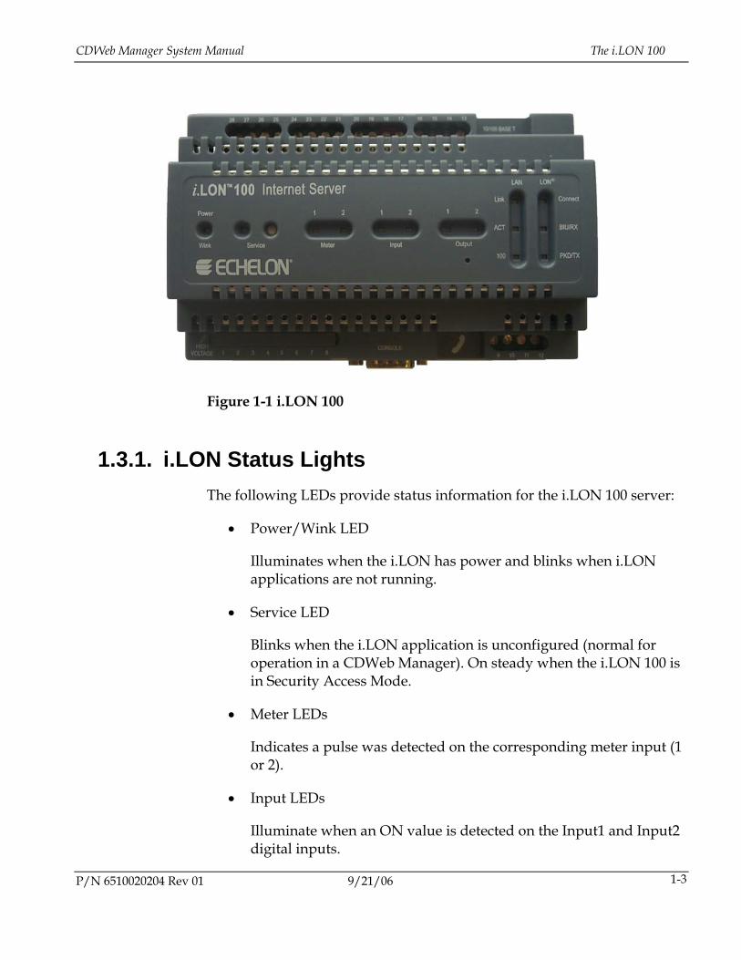
Figure 1-1 i.LON 100
1.3.1. i.LON Status Lights The following LEDs provide status information for the i.LON 100 server:
• Power/Wink LED
Illuminates when the i.LON has power and blinks when i.LON applications are not running.
• Service LED
Blinks when the i.LON application is unconfigured (normal for operation in a CDWeb Manager). On steady when the i.LON 100 is in Security Access Mode.
• Meter LEDs
Indicates a pulse was detected on the corresponding meter input (1 or 2).
• Input LEDs
Illuminate when an ON value is detected on the Input1 and Input2 digital inputs.
P/N 6510020204 Rev 01 9/21/06 1-3
System Overview CDWeb Manager System Manual
9/21/06 P/N 6510020204 Rev 01 1-4
• Output LEDs
Illuminate when the corresponding output’s relay is closed.
• LAN Link
Illuminates when an Ethernet connection is present.
• LAN ACT
Illuminates with Ethernet activity.
• LAN 100
Illuminates when the Ethernet connection is communicating at 100 Mbps.
• LON Connect
Illuminates when an OpenLDV session is open.
• LON BIU/RX
Illuminates when LON data is being received.
• LON PKD/TX
Illuminates when LON data is being transmitted.
Further details on the i.LON 100 can be read in the i.LON 100 Internet Server User’s Manual.
1.4. The CDWeb Processor CDWeb Managers that are required to communicate to CD control systems other than Honeywell’s Performance CD system require the addition of a CDWeb Processor. This processor acts as a protocol translator between the QCS and the i.LON 100, converting the ODX, RTU, or SCL host messages to LON over TCP/IP and vice versa.
The CDWeb Processor is an industrial PC running Windows XP with a minimal RAE 4.0 installation. ODX client, RTU slave, or SCL slave applications communicate with the host QCS placing (and retrieving)
CDWeb Manager System Manual HC900 Hybrid Controller
information directly in the RTDR database. The CDWeb LON server application provides the interface between the database and the actuators through the i.LON.
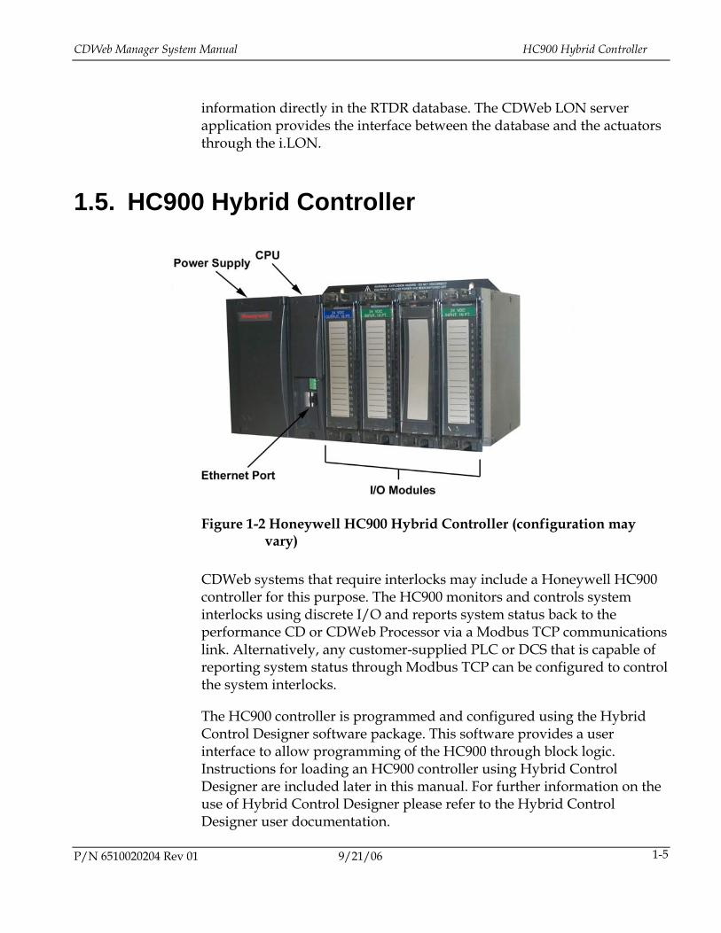
1.5. HC900 Hybrid Controller
Figure 1-2 Honeywell HC900 Hybrid Controller (configuration may
vary)
CDWeb systems that require interlocks may include a Honeywell HC900 controller for this purpose. The HC900 monitors and controls system interlocks using discrete I/O and reports system status back to the performance CD or CDWeb Processor via a Modbus TCP communications link. Alternatively, any customer-supplied PLC or DCS that is capable of reporting system status through Modbus TCP can be configured to control the system interlocks.
The HC900 controller is programmed and configured using the Hybrid Control Designer software package. This software provides a user interface to allow programming of the HC900 through block logic. Instructions for loading an HC900 controller using Hybrid Control Designer are included later in this manual. For further information on the use of Hybrid Control Designer please refer to the Hybrid Control Designer user documentation.
P/N 6510020204 Rev 01 9/21/06 1-5
System Overview CDWeb Manager System Manual
9/21/06 P/N 6510020204 Rev 01 1-6
Although the HC900 includes a lithium backup battery to save run-time data and power the real-time clock in the event of a power loss, this feature is not used on CDWeb Manager systems. In the event that the battery is removed or discharged, the CDWeb system will continue to function correctly, however a red warning LED on the HC900 processor will blink five times to indicate the fault.
1.5.1. Controller Mode Switch The three-position mode switch is located inside the door of the HC900 CPU. The left position is Run-locked mode, the middle position is Run & Program mode, and the right position is Program-locked mode. The normal position for operation in a CDWeb system is either Run-locked, or Run & Program.
1.5.2. Status LED The HC900 status LED gives an indication of the controller’s mode. Flashing green indicate Run mode, solid green indicate Program Mode, while flashing red indicates and error code. Refer to the Hybrid Controller Installation and User Guide for more details.
6510020204 Rev 01 2-1
2. Installation Requirements
2.1. CDWeb Manager Environmental Specification
All Honeywell CDWeb Managers have the following environmental specification:
Cabinet Rating: NEMA 4, IP 66 Operating Temp.: 0 to 50°C* Storage Temp.: -20 to 75°C Operating Humidity: 30 to 90% @ 40°C Relative Humidity(non-
condensing) Storage Humidity: 20 to 90% Relative Humidity(non-
condensing)
*without CDWeb Processor. Systems with CDWeb processor have a maximum operating temperature of 40°C.
2.2. CDWeb Manager Electrical Specification
2.2.1. Mill Power Requirements This specification defines the requirements for AC source power for the operation of the CDWeb Manager. For more details on power requirements, see the Installation Requirements for Conformance to Standards manual, part number 65 1002 0134, shipped with the CDWeb Manager.
Installation Requirements CDWeb Manager System Manual
9/21/06 P/N 6510020204 Rev 01 2-2
2.2.2. Voltage, Current and Frequency Ratings The required source voltage for the CDWeb Manager is 100/120 VAC or 200/230 VAC. The current requirements for the various CDWeb Managers depend on actuator type and system size. Consult Engineering drawings to determine the requirements for a specific system.
The source frequency should be 60 Hz ± 2 Hz, or at 50 Hz ± 2 Hz. Short or long term variations outside these limits degrade system reliability.
The voltage supply must not deviate from these specifications. Condition the supply to correct for any drift that may occur from facility load changes, or starting and running current requirements.
2.2.3. Installation of Distribution Circuits Selection of wire sizes, cable type, color, conduit, switch panel, breakers, transformers, and miscellaneous hardware, must conform to local electrical codes and to standard practice. Circuit breakers must be sized according to Honeywell equipment power requirements and installed in close proximity to the equipment they power. Refer to the cable/conduit schedule included with the system drawings for specific details.
2.3. CDWeb Manager Installation
2.3.1. Enclosure Installation The CDWeb Manager enclosure is shipped from the factory unchanged from the original manufacturer’s NEMA 4 condition. Any modifications done to the enclosure during installation can compromise the seal integrity of the enclosure and reduce the enclosure performance to below NEMA 4. Consult Honeywell if a non-standard installation method is to be used.
All CDWeb Managers are equipped with grounding terminals to be connected to mill ground during installation as per standard practice or regional regulations. Failure to provide a primary ground connection to the grounding terminals (consult system electrical drawings for exact
CDWeb Manager System Manual CDWeb Manager Installation
P/N 6510020204 Rev 01 9/21/06 2-3
locations) can lead to personal injury and may be in violation of local electrical code.
2.3.2. Cable Installation Where possible, cable entry into the CDWeb Manager enclosure should be from the bottom to prevent condensation or moisture in the cable conduit from dripping into the enclosure. All cables and conduits must use water-tight cable glands or fittings to preserve the NEMA 4 rating of the enclosure.
Cables and wires are to be terminated according to the control cabinet electrical wiring diagrams supplied with the system. Refer to the wire and cable schedule provided with the system for minimum recommended cable sizes and types.

6510020204 Rev 01 3-1
3. Utilities
3.1. Introduction The CDWeb Manager is shipped factory configured to operate with the specified Supervisory Control System. During system installation and maintenance, it may be necessary to change some of the configuration and tuning values used by the system, or to replace components of the CDWeb system. Various utilities are required to assist with these changes.
3.1.1. CDWeb Explorer CDWeb Explorer is a software utility designed and created specifically for the installation and maintenance of a CDWeb actuator system. Its major functions include:
• Installing new or replacement actuator controllers
• Viewing runtime diagnostic information
• Configuring/tuning/calibrating actuator controllers
• Monitoring actuator controller status messages
• Updating actuator firmware
• Defining and generating network layout (.csv and .map files)
Utilities CDWeb Manager System Manual
9/21/06 P/N 6510020204 Rev 01 3-2
3.1.2. Hybrid Control Designer Hybrid Control Designer is a software utility designed specifically for the HC900 series of controllers. Its major functions include:
• Viewing and modifying interlock block logic
• Viewing and modifying I/O configuration
• Changing the network parameters of the HC900 processor
3.1.3. Internet Explorer Internet Explorer, or any other standard internet browser, is required to access the maintenance features of the i.LON100. The major functions it is used for in a CDWeb system are:
• Modifying network parameters of the i.LON100
• Updating the firmware of the i.LON100
3.1.4. Windows Remote Desktop Windows Remote Desktop, a standard feature with Windows XP, is used to configure a CDWeb Processor when connecting a monitor and keyboard directly to the processor is not possible. It can be used for the following functions:
• Modifying CDWeb processor communications parameters
• Configuring a replacement CDWeb Processor
3.1.5. Personal Computer All of the utilities previously described in this chapter require a personal computer. The minimum requirements for this PC are:
• CPU: Pentium, 300MHz
• Operating System: Windows 2000, Windows XP
CDWeb Manager System Manual CDWeb Explorer
P/N 6510020204 Rev 01 9/21/06 3-3
• Display Color: Minimum resolution (256 color x 1024 x 768 resolution)
• Pointing Device: Mouse, Trackball or compatible device
• RAM: 128MB Minimum
• Removable Disk Drive: CD ROM Drive
• Ports: Ethernet
3.2. CDWeb Explorer The main utility used for configuring and maintaining a CDWeb actuator system is CDWeb Explorer.
3.2.1. The .web File CDWeb Explorer is based around a system specific .web file. Normally this file is name CDWeb.web, but any standard file name with the .web extension will work. In general, there should be no need to modify a .web file for a CDWeb system as it is set up at the time of manufacture.
The .web file is simply a text-based database that contains information relevant to a specific CDWeb system. It describes how many, and what type of actuators are present in the system. Each section of the .web file refers to a specific element of the CDWeb system.
[CDWeb Explorer]
The CDWeb Explorer section allows you to set the default view of the system when the .web file is first loaded. This view can be changed dynamically at any time during a CDWeb Explorer session, but each new session will start with the default view defined in the .web file.
[CDWeb Explorer]
View=location
Utilities CDWeb Manager System Manual
9/21/06 P/N 6510020204 Rev 01 3-4
[CDWeb]
The CDWeb section is used to define the number of beams, the number of controllers, and a name for the system that will be displayed.
[CDWeb]
Display Label=Example Web
Number of Beams=1
Number of Controllers=35
[CDWeb Manager]
The CDWeb Manager section holds the definitions for number of CDWeb processors and the number of routers attached to the system.
[CDWeb Manager]
Number of Processors=1
Number of Routers=1
[Processor x]
There is a processor section for each processor connected to a specific CDWeb system (normally only 1 processor is connected). This section contains the display label, the CDWeb processor name, the network address of the CDWeb processor, the type of Processor, and which beams are controlled by this processor.
[Processor 1]
Display Label=
Name=
Address=++
Processor Type=(LDV,FC,QNX,Da Vinci)
Beam 1 = (non zero value)
Tool = (Always = 1)
Interface index = (0…X, where X is the index of the iLON on the performance CD system)

CDWeb Manager System Manual CDWeb Explorer
P/N 6510020204 Rev 01 9/21/06 3-5
LDV address = X.CDWEB.CP1
LON Link Type = Processor or SLTA)
++ The address defined in this section is simply the default IP address where CDWeb Explorer looks for the LON server application (CDWebNET.exe). If the IP address of the LON server has been changed it can be found using the Locate option from the context menu. This function also dynamically updates the .web file to look at the new address.
[Beam x]
There is one Beam section for each beam included in a system. This section defines the beam Display label, the type of actuator, the actuator version, and a listing of the actuators on a specific beam.
[Beam 1]
Display Label=Beam
Actuator Type=CalcoilCW
Actuator Version=112
Controller 1=1
...
Controller 35=1
The controllers attached to the beam are defined in the same way as the beams attached to a processor, that is, any non-zero value will define the controller to be attached to the beam.
[Router x]
There will be one Router section for each router in the CDWeb system. This section defines the name of the router, its configuration setting, and which actuators are connected to it.
[Router 1]
Name=Router_b1_s1
Configuration=configured
Utilities CDWeb Manager System Manual
9/21/06 P/N 6510020204 Rev 01 3-6
Visible = 0 (first router in each beam is not visible, subsequent routers visible = 1)
Controller 1=1
...
Controller 35=1
[Controller 1]
For multi zone controllers there is a section for each controller to indicate which physical zone is controlled by which zone on the controller. The NeuronID of the controller will also be stored in this section once the zone has been confirmed.
NeuronID=00 04 23 20 77 00
ZoneA=1
ZoneB=2
ZoneC=3
ZoneD=4
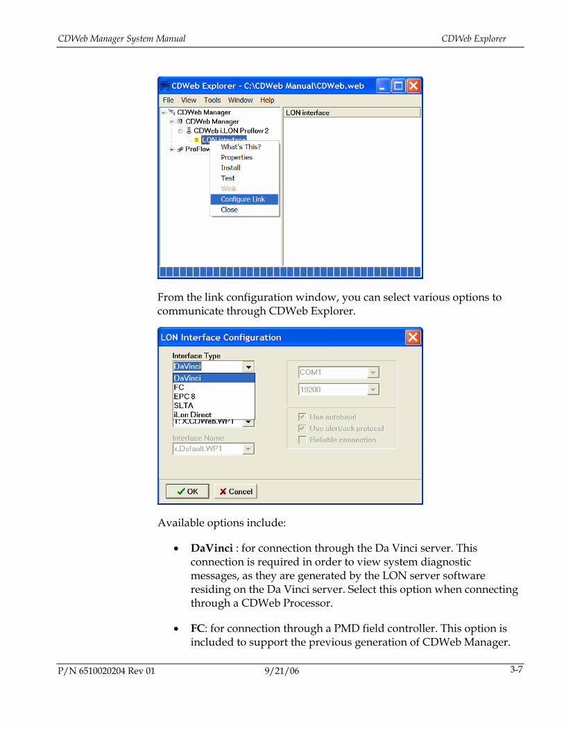
3.2.2. Connecting to the System Using CDWeb Explorer CDWeb Explorer provides several ways to connect to the actuator system for installation and maintenance. With the .web file open, right click in the LON interface and select configure link.
CDWeb Manager System Manual CDWeb Explorer
From the link configuration window, you can select various options to communicate through CDWeb Explorer.
Available options include:
• DaVinci : for connection through the Da Vinci server. This connection is required in order to view system diagnostic messages, as they are generated by the LON server software residing on the Da Vinci server. Select this option when connecting through a CDWeb Processor.
• FC: for connection through a PMD field controller. This option is included to support the previous generation of CDWeb Manager.
P/N 6510020204 Rev 01 9/21/06 3-7
Utilities CDWeb Manager System Manual
• EPC-8: for connection through a CDWeb Manager with an EPC-8 CDWeb Processor. This option is included to support the original style of CDWeb Manager.
• SLTA: for connection through a Serial LONTalk Adapter (SLTA).
• i.LON Direct: This option is for connection to the actuators directly through the i.LON, bypassing the LON server software on the Da Vinci server. Installation of the i.LON driver software on the maintenance PC is required.
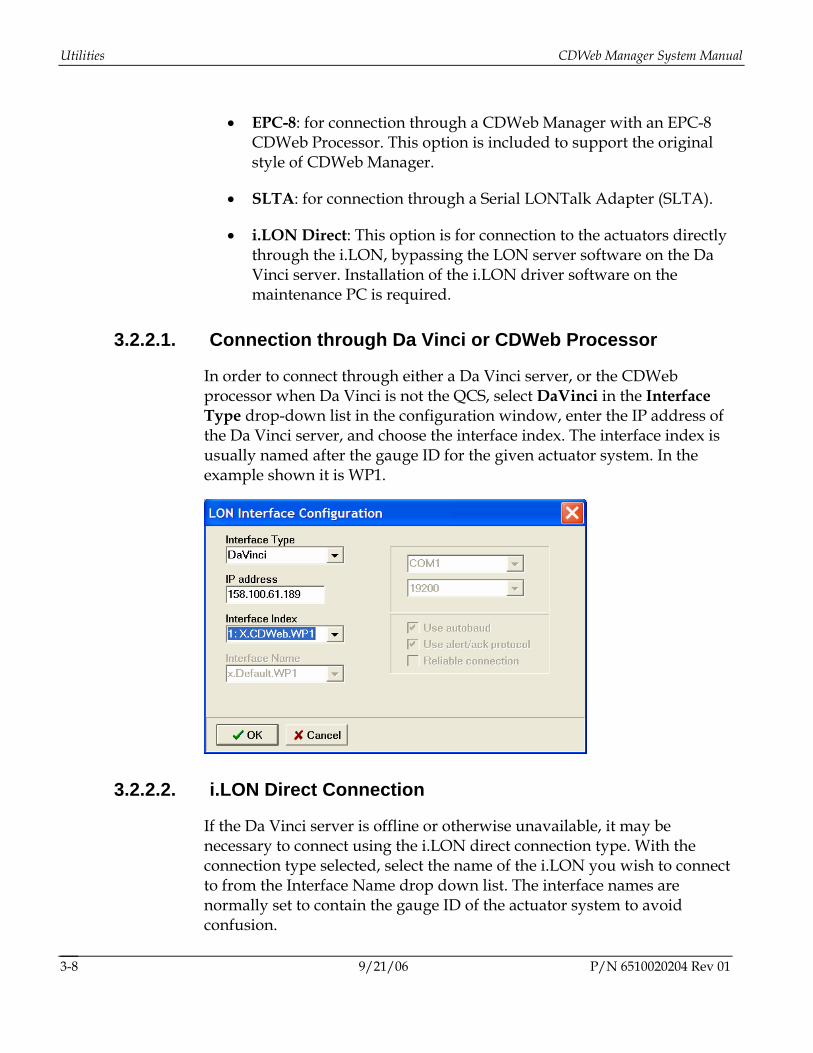
3.2.2.1. Connection through Da Vinci or CDWeb Processor
In order to connect through either a Da Vinci server, or the CDWeb processor when Da Vinci is not the QCS, select DaVinci in the Interface Type drop-down list in the configuration window, enter the IP address of the Da Vinci server, and choose the interface index. The interface index is usually named after the gauge ID for the given actuator system. In the example shown it is WP1.
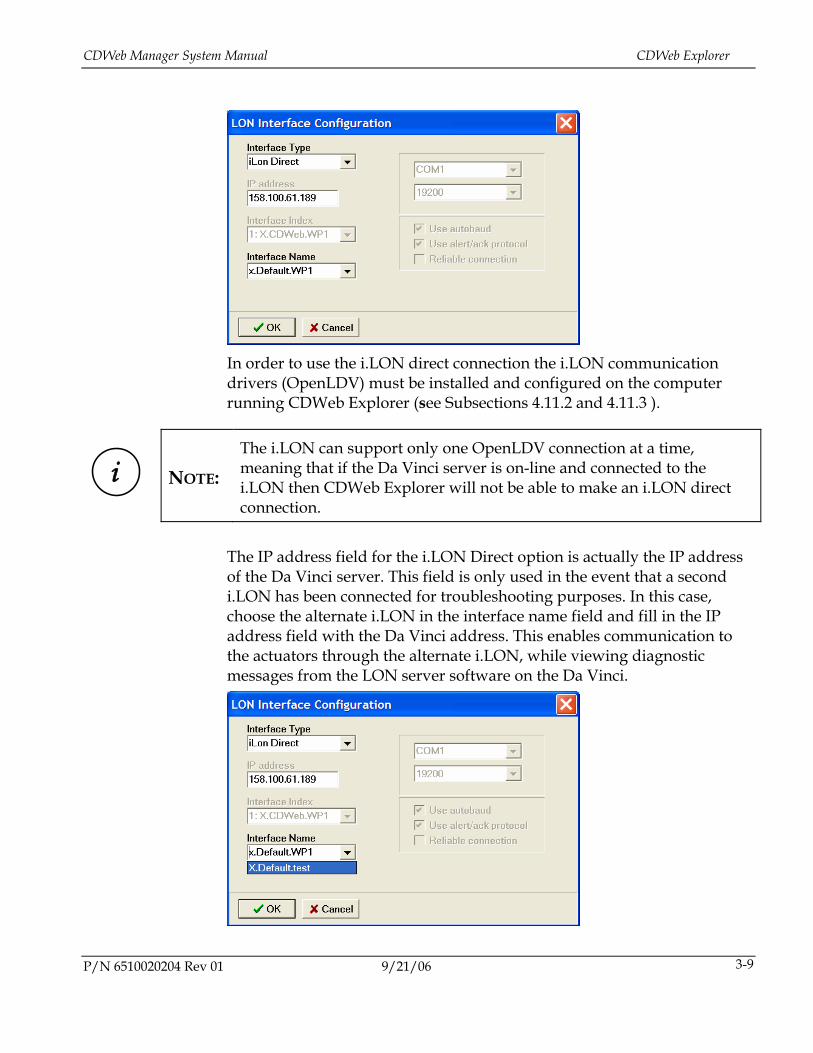
3.2.2.2. i.LON Direct Connection
If the Da Vinci server is offline or otherwise unavailable, it may be necessary to connect using the i.LON direct connection type. With the connection type selected, select the name of the i.LON you wish to connect to from the Interface Name drop down list. The interface names are normally set to contain the gauge ID of the actuator system to avoid confusion.
9/21/06 P/N 6510020204 Rev 01 3-8
CDWeb Manager System Manual CDWeb Explorer
In order to use the i.LON direct connection the i.LON communication drivers (OpenLDV) must be installed and configured on the computer running CDWeb Explorer (see Subsections 4.11.2 and 4.11.3 ).
i
NOTE: The i.LON can support only one OpenLDV connection at a time, meaning that if the Da Vinci server is on-line and connected to the i.LON then CDWeb Explorer will not be able to make an i.LON direct connection.
The IP address field for the i.LON Direct option is actually the IP address of the Da Vinci server. This field is only used in the event that a second i.LON has been connected for troubleshooting purposes. In this case, choose the alternate i.LON in the interface name field and fill in the IP address field with the Da Vinci address. This enables communication to the actuators through the alternate i.LON, while viewing diagnostic messages from the LON server software on the Da Vinci.
P/N 6510020204 Rev 01 9/21/06 3-9

6510020204 Rev 01 4-1
4. Common Tasks
This chapter contains descriptions of how to perform common tasks for CDWeb systems. Basic instructions are given for loading and communicating with the HC900 controller, but for a fuller understanding of its capabilities and features, reading the HC900 documentation is recommended. Before attempting these procedures, ensure that the software tools have been properly installed on a suitable maintenance computer.
4.1. View and Log CDWeb Diagnostic Information CDWeb diagnostic information can be viewed only when connected through a computer running the LON server application (CDWebNET.exe). The LON Server software will be running on either on the Da Vinci server or on the CDWeb Processor required for legacy and MXOpen systems
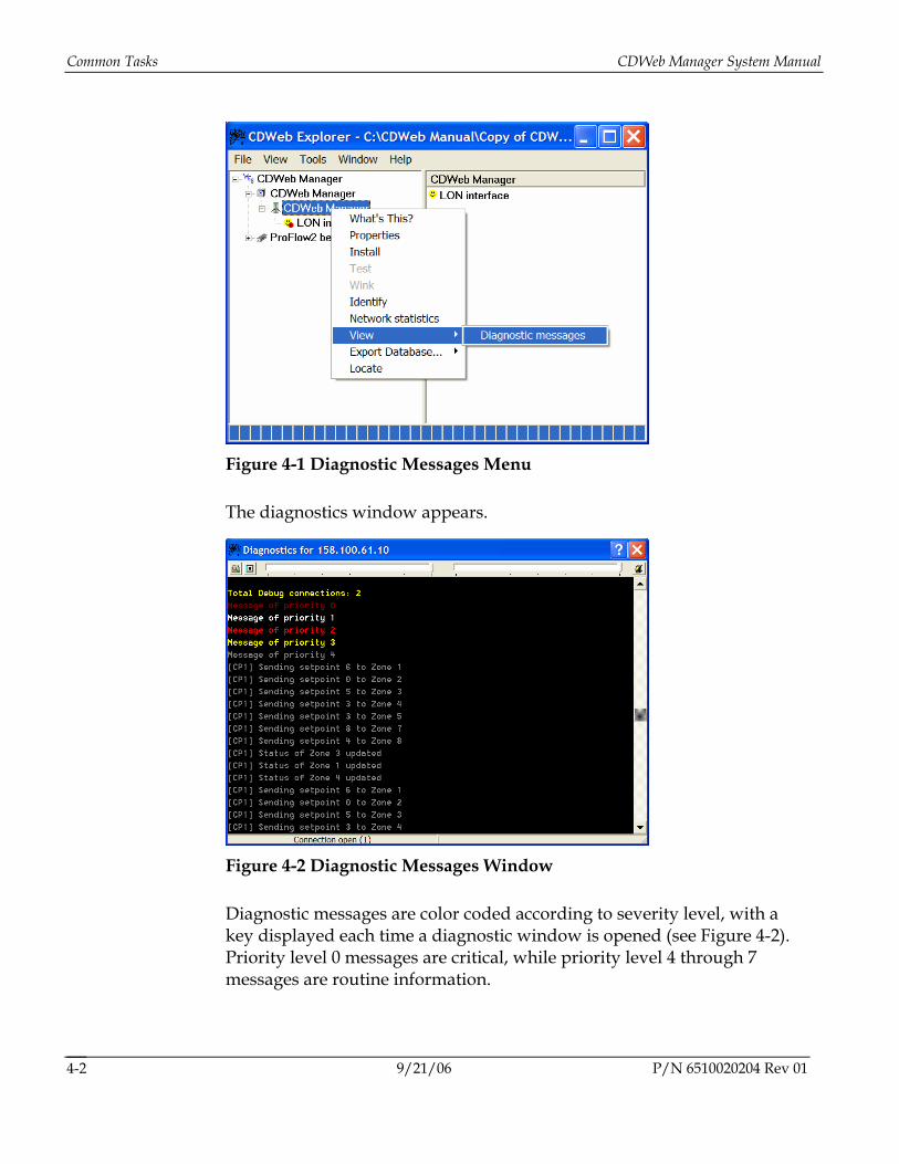
To see the diagnostic messages: using CDWeb Explorer, right-click on the CDWeb Processor and select View Diagnostic Messages from the context menu.
Common Tasks CDWeb Manager System Manual
Figure 4-1 Diagnostic Messages Menu
The diagnostics window appears.
Figure 4-2 Diagnostic Messages Window
Diagnostic messages are color coded according to severity level, with a key displayed each time a diagnostic window is opened (see Figure 4-2). Priority level 0 messages are critical, while priority level 4 through 7 messages are routine information.
9/21/06 P/N 6510020204 Rev 01 4-2
CDWeb Manager System Manual Configure and Tune Actuators
The display can be paused using the button in the top left corner of the window. A file log can be enabled using the button in the top right corner of the window.
The filter button can be used when there are multiple CD actuator systems connected in order to filter out messages for systems which do not require troubleshooting.
The slider bars at the top are used to filter the message severity level. Moving the slider to the left filters out lower priority messages, while moving it to the extreme right allows all messages through. The left slider is used to filter message shown on the display, while the right slider is used to filter messages sent to the log file (if active).
4.2. Configure and Tune Actuators Each actuator needs certain information in order to operate correctly. This information includes how often it should communicate with the CDWeb Manager.
Configuring an actuator lets it know what type of actuator it is and gives it certain values required for LON communications. Tuning provides operational limits and alarm thresholds. Calibration consists of the values required to transform sensor inputs into useful outputs.
An actuator is configured by sending it a network variable message for nci_ActConfig with meaningful values. Similarly, tuning an actuator consists of sending it a new nci_ActTuning network variable.
For detailed information regarding the tuning and configuration of specific actuators please refer to the appropriate actuator system manual.
4.2.1. Configuring Actuators 1. Start CDWeb Explorer and load the .web file for the system.
2. Configure the CDWeb Explorer link (see Chapter 3).
P/N 6510020204 Rev 01 9/21/06 4-3
Common Tasks CDWeb Manager System Manual
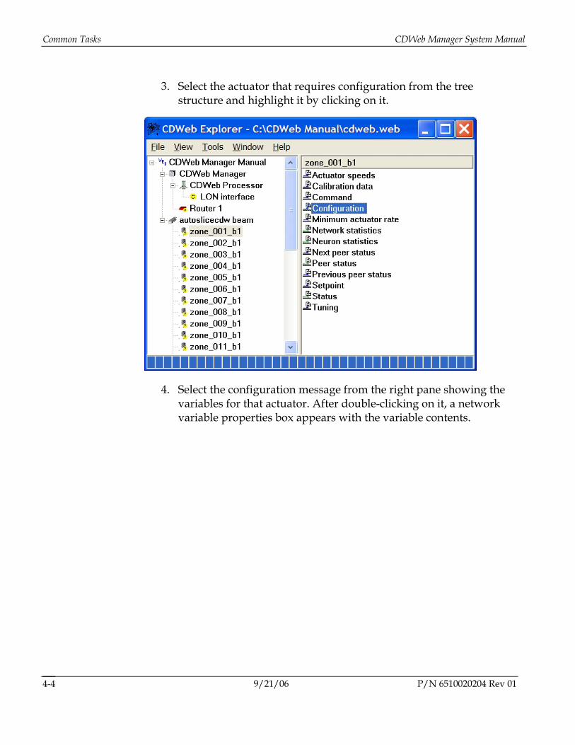
3. Select the actuator that requires configuration from the tree structure and highlight it by clicking on it.
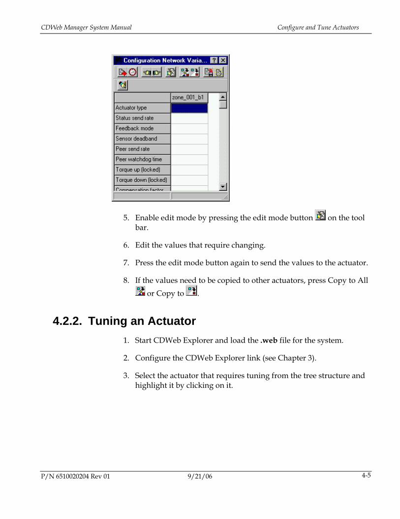
4. Select the configuration message from the right pane showing the variables for that actuator. After double-clicking on it, a network variable properties box appears with the variable contents.
9/21/06 P/N 6510020204 Rev 01 4-4
CDWeb Manager System Manual Configure and Tune Actuators
5. Enable edit mode by pressing the edit mode button on the tool bar.
6. Edit the values that require changing.
7. Press the edit mode button again to send the values to the actuator.
8. If the values need to be copied to other actuators, press Copy to All or Copy to .
4.2.2. Tuning an Actuator 1. Start CDWeb Explorer and load the .web file for the system.
2. Configure the CDWeb Explorer link (see Chapter 3).
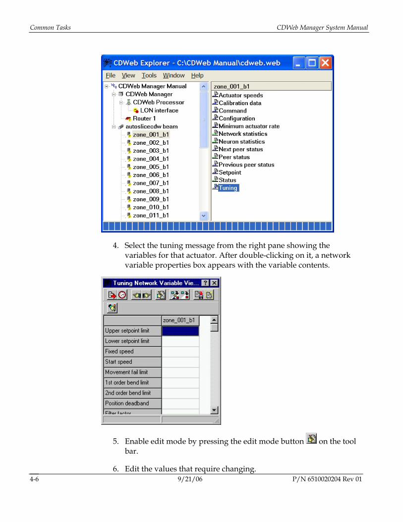
3. Select the actuator that requires tuning from the tree structure and highlight it by clicking on it.
P/N 6510020204 Rev 01 9/21/06 4-5
Common Tasks CDWeb Manager System Manual
4. Select the tuning message from the right pane showing the variables for that actuator. After double-clicking on it, a network variable properties box appears with the variable contents.
5. Enable edit mode by pressing the edit mode button on the tool bar.
9/21/06 P/N 6510020204 Rev 01 6. Edit the values that require changing.
4-6
CDWeb Manager System Manual Save and Restore Configuration and Tuning
7. Press the edit mode button again to send the values to the actuator.
8. If the values need to be copied to other actuators, select Copy to All or Copy to .
4.3. Save and Restore Configuration and Tuning In some cases it can be useful or even necessary to save the actuator tuning and configurations values. For example, if the actuator firmware is being upgraded to take advantage of some new actuator features, the tuning and configuration data can be saved, and then restored to the actuators when the process is complete.
To save configuration or tuning information:
1. Start CDWeb Explorer and load the .web file for the system.
2. Ensure the Actuator communication interface is functional.
3. Select an actuator from the tree structure and highlight it by clicking on it.
4. Select the tuning or configuration message from the right pane showing the variables for that actuator. After double-clicking on it, a network variable properties box appears with the variable contents.
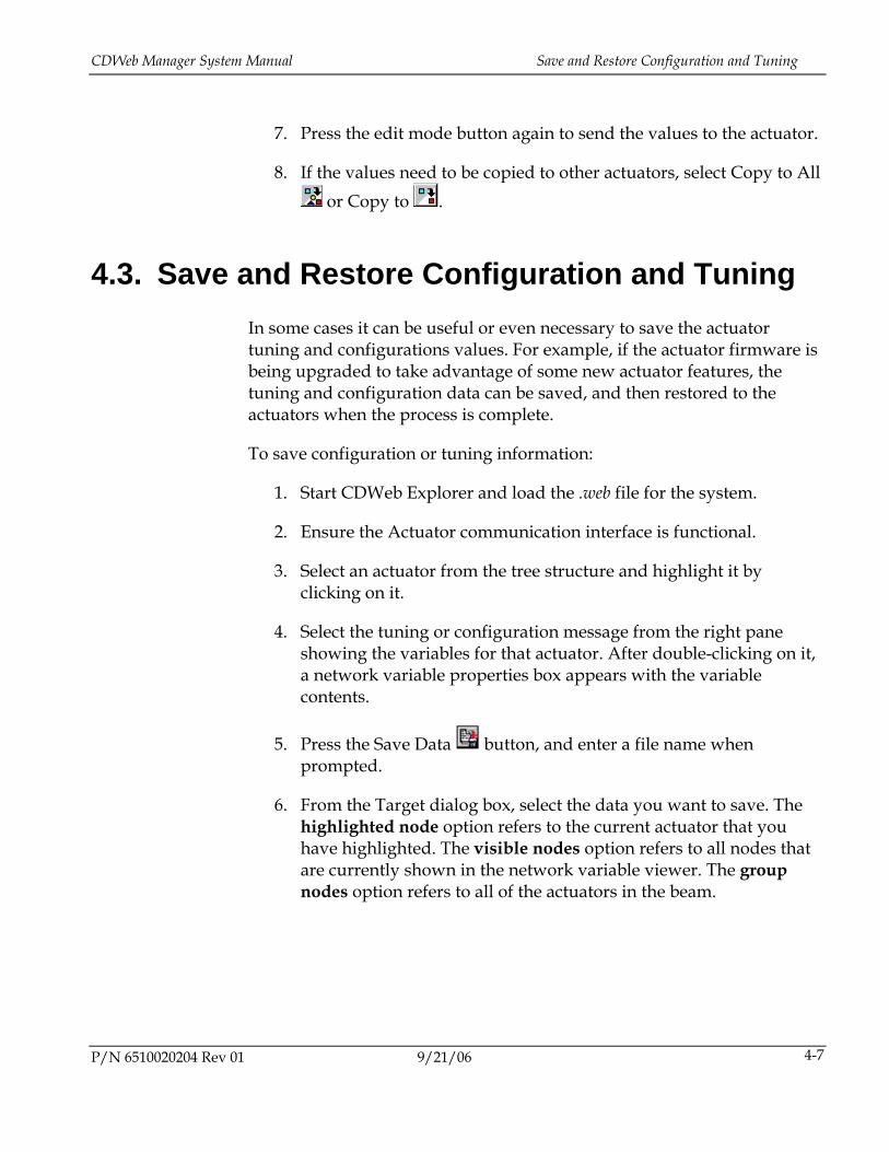
5. Press the Save Data button, and enter a file name when prompted.
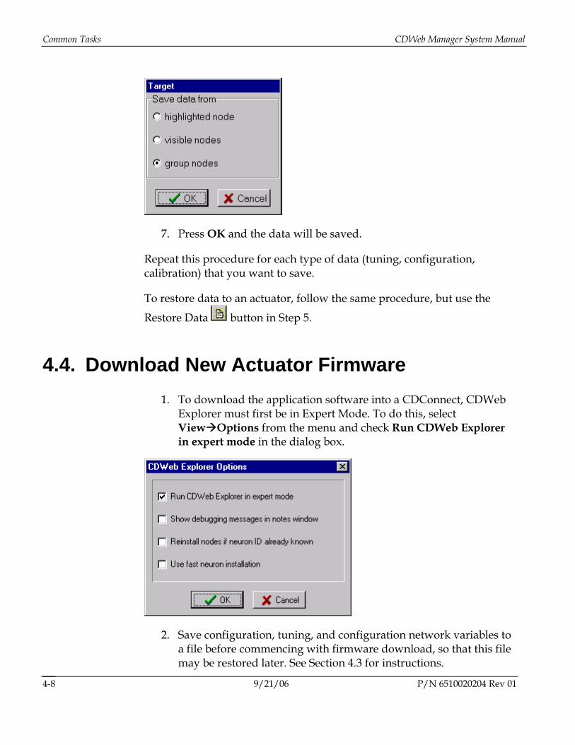
6. From the Target dialog box, select the data you want to save. The highlighted node option refers to the current actuator that you have highlighted. The visible nodes option refers to all nodes that are currently shown in the network variable viewer. The group nodes option refers to all of the actuators in the beam.
P/N 6510020204 Rev 01 9/21/06 4-7
Common Tasks CDWeb Manager System Manual
7. Press OK and the data will be saved.
Repeat this procedure for each type of data (tuning, configuration, calibration) that you want to save.
To restore data to an actuator, follow the same procedure, but use the
Restore Data button in Step 5.
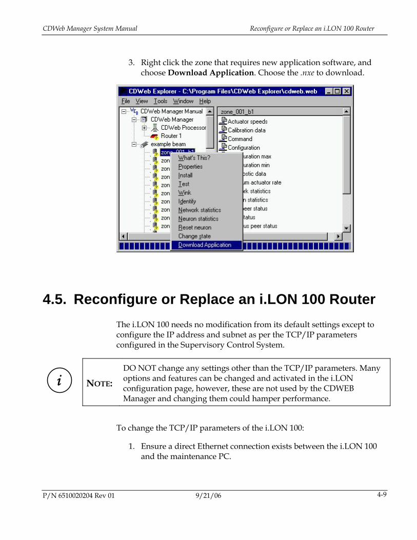
4.4. Download New Actuator Firmware 1. To download the application software into a CDConnect, CDWeb
Explorer must first be in Expert Mode. To do this, select View Options from the menu and check Run CDWeb Explorer in expert mode in the dialog box.
2. Save configuration, tuning, and configuration network variables to a file before commencing with firmware download, so that this file may be restored later. See Section 4.3 for instructions.
9/21/06 P/N 6510020204 Rev 01 4-8
CDWeb Manager System Manual Reconfigure or Replace an i.LON 100 Router
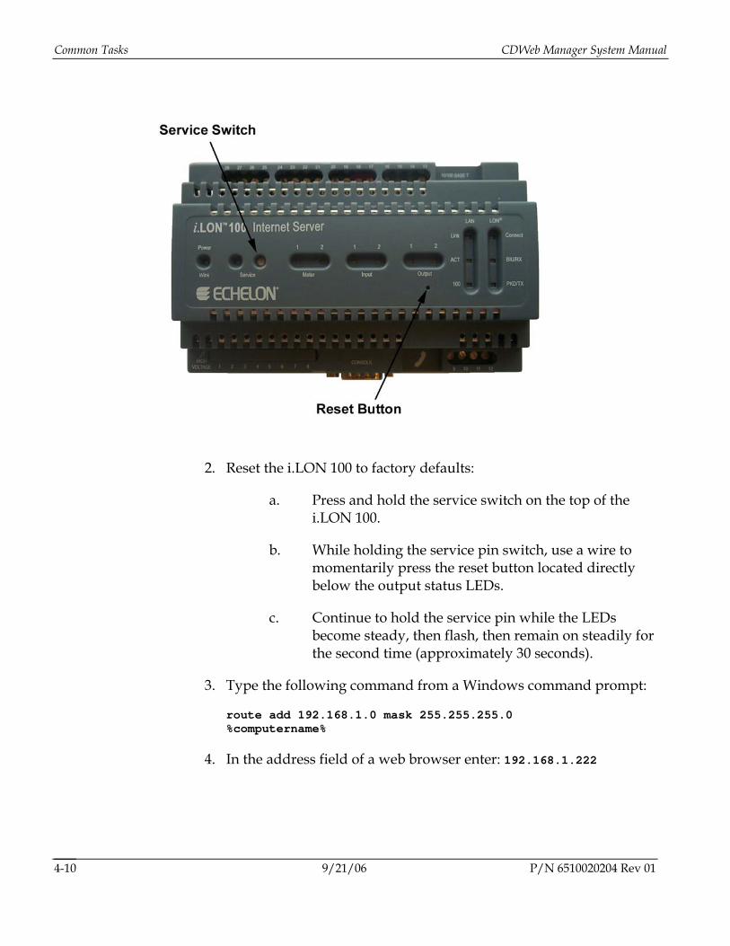
3. Right click the zone that requires new application software, and choose Download Application. Choose the .nxe to download.
4.5. Reconfigure or Replace an i.LON 100 Router The i.LON 100 needs no modification from its default settings except to configure the IP address and subnet as per the TCP/IP parameters configured in the Supervisory Control System.
i
NOTE: DO NOT change any settings other than the TCP/IP parameters. Many options and features can be changed and activated in the i.LON configuration page, however, these are not used by the CDWEB Manager and changing them could hamper performance.
To change the TCP/IP parameters of the i.LON 100:
1. Ensure a direct Ethernet connection exists between the i.LON 100 and the maintenance PC.
P/N 6510020204 Rev 01 9/21/06 4-9
Common Tasks CDWeb Manager System Manual
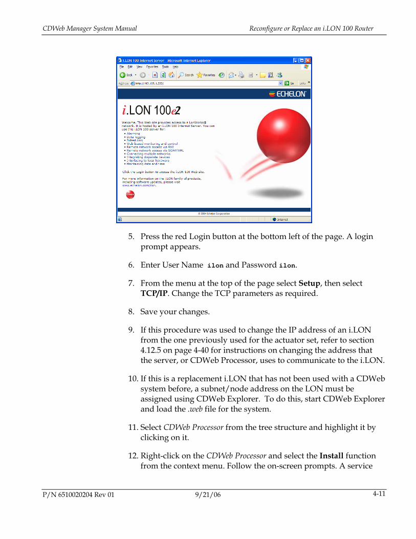
2. Reset the i.LON 100 to factory defaults:
a. Press and hold the service switch on the top of the i.LON 100.
b. While holding the service pin switch, use a wire to momentarily press the reset button located directly below the output status LEDs.
c. Continue to hold the service pin while the LEDs become steady, then flash, then remain on steadily for the second time (approximately 30 seconds).
3. Type the following command from a Windows command prompt:
route add 192.168.1.0 mask 255.255.255.0 %computername%
4. In the address field of a web browser enter: 192.168.1.222
9/21/06 P/N 6510020204 Rev 01 4-10
CDWeb Manager System Manual Reconfigure or Replace an i.LON 100 Router
5. Press the red Login button at the bottom left of the page. A login prompt appears.
6. Enter User Name ilon and Password ilon.
7. From the menu at the top of the page select Setup, then select TCP/IP. Change the TCP parameters as required.
8. Save your changes.
9. If this procedure was used to change the IP address of an i.LON from the one previously used for the actuator set, refer to section 4.12.5 on page 4-40 for instructions on changing the address that the server, or CDWeb Processor, uses to communicate to the i.LON.
10. If this is a replacement i.LON that has not been used with a CDWeb system before, a subnet/node address on the LON must be assigned using CDWeb Explorer. To do this, start CDWeb Explorer and load the .web file for the system.
11. Select CDWeb Processor from the tree structure and highlight it by clicking on it.
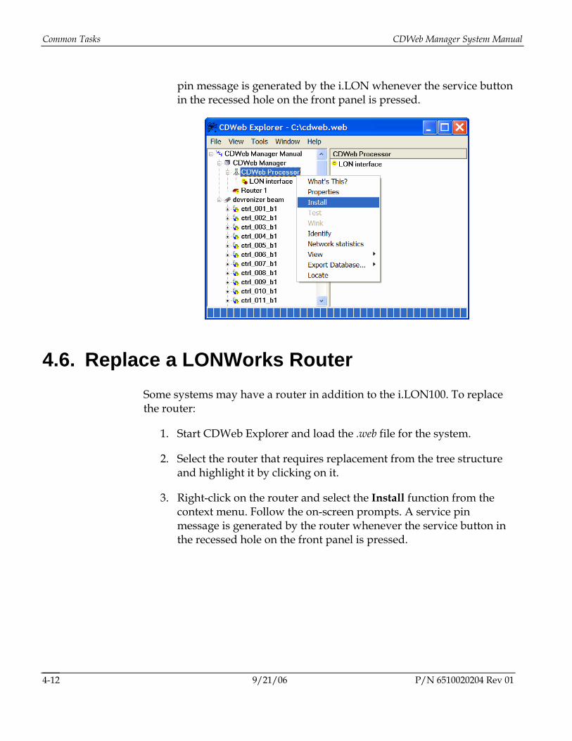
12. Right-click on the CDWeb Processor and select the Install function from the context menu. Follow the on-screen prompts. A service
P/N 6510020204 Rev 01 9/21/06 4-11
Common Tasks CDWeb Manager System Manual
pin message is generated by the i.LON whenever the service button in the recessed hole on the front panel is pressed.
4.6. Replace a LONWorks Router Some systems may have a router in addition to the i.LON100. To replace the router:
1. Start CDWeb Explorer and load the .web file for the system.
2. Select the router that requires replacement from the tree structure and highlight it by clicking on it.
3. Right-click on the router and select the Install function from the context menu. Follow the on-screen prompts. A service pin message is generated by the router whenever the service button in the recessed hole on the front panel is pressed.
9/21/06 P/N 6510020204 Rev 01 4-12
CDWeb Manager System Manual Establish a Network Connection to the HC900
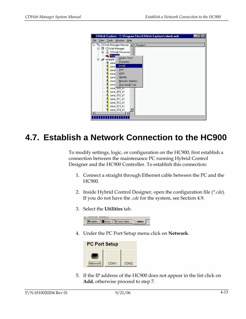
4.7. Establish a Network Connection to the HC900 To modify settings, logic, or configuration on the HC900, first establish a connection between the maintenance PC running Hybrid Control Designer and the HC900 Controller. To establish this connection:
1. Connect a straight through Ethernet cable between the PC and the HC900.
2. Inside Hybrid Control Designer, open the configuration file (*.cde). If you do not have the .cde for the system, see Section 4.9.
3. Select the Utilities tab.
4. Under the PC Port Setup menu click on Network.
5. If the IP address of the HC900 does not appear in the list click on Add, otherwise proceed to step 7.
P/N 6510020204 Rev 01 9/21/06 4-13
Common Tasks CDWeb Manager System Manual
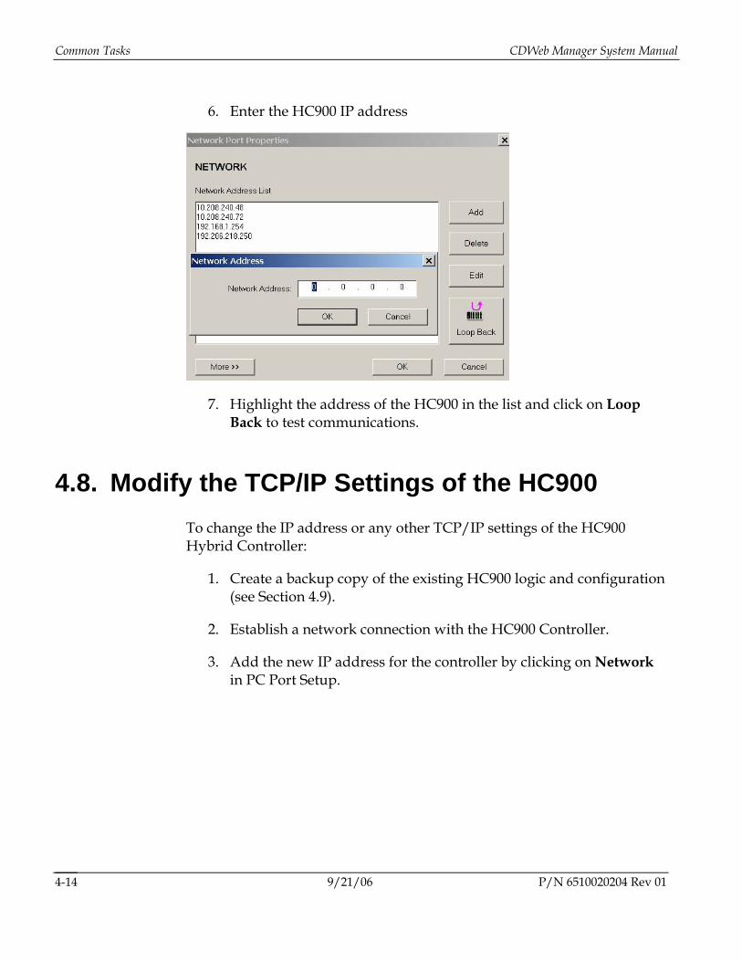
6. Enter the HC900 IP address
7. Highlight the address of the HC900 in the list and click on Loop Back to test communications.
4.8. Modify the TCP/IP Settings of the HC900 To change the IP address or any other TCP/IP settings of the HC900 Hybrid Controller:
1. Create a backup copy of the existing HC900 logic and configuration (see Section 4.9).
2. Establish a network connection with the HC900 Controller.
3. Add the new IP address for the controller by clicking on Network in PC Port Setup.
9/21/06 P/N 6510020204 Rev 01 4-14
CDWeb Manager System Manual Modify the TCP/IP Settings of the HC900
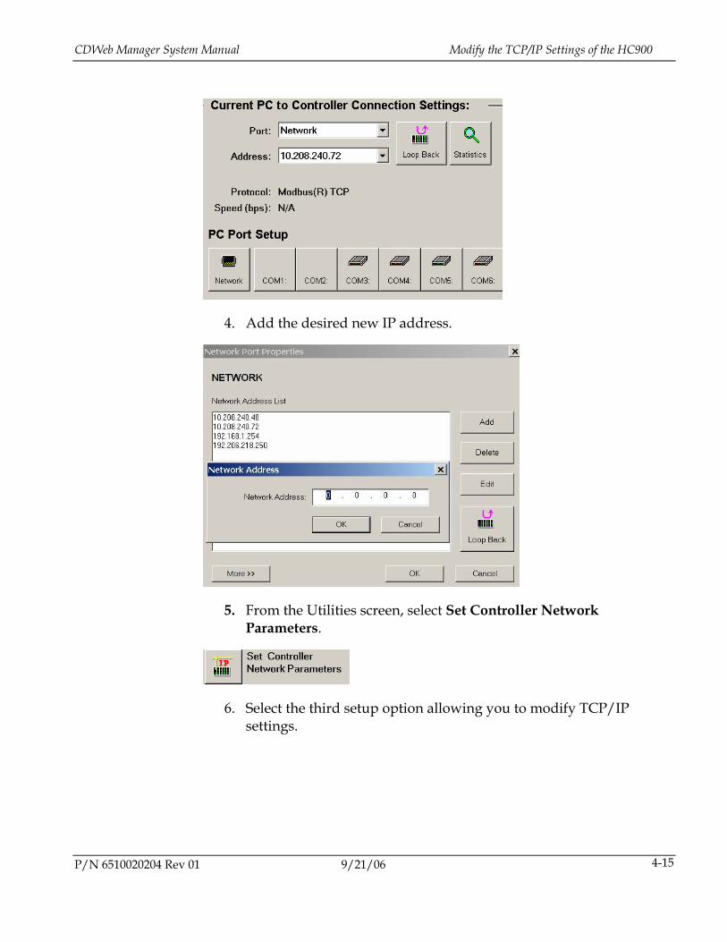
4. Add the desired new IP address.
5. From the Utilities screen, select Set Controller Network Parameters.
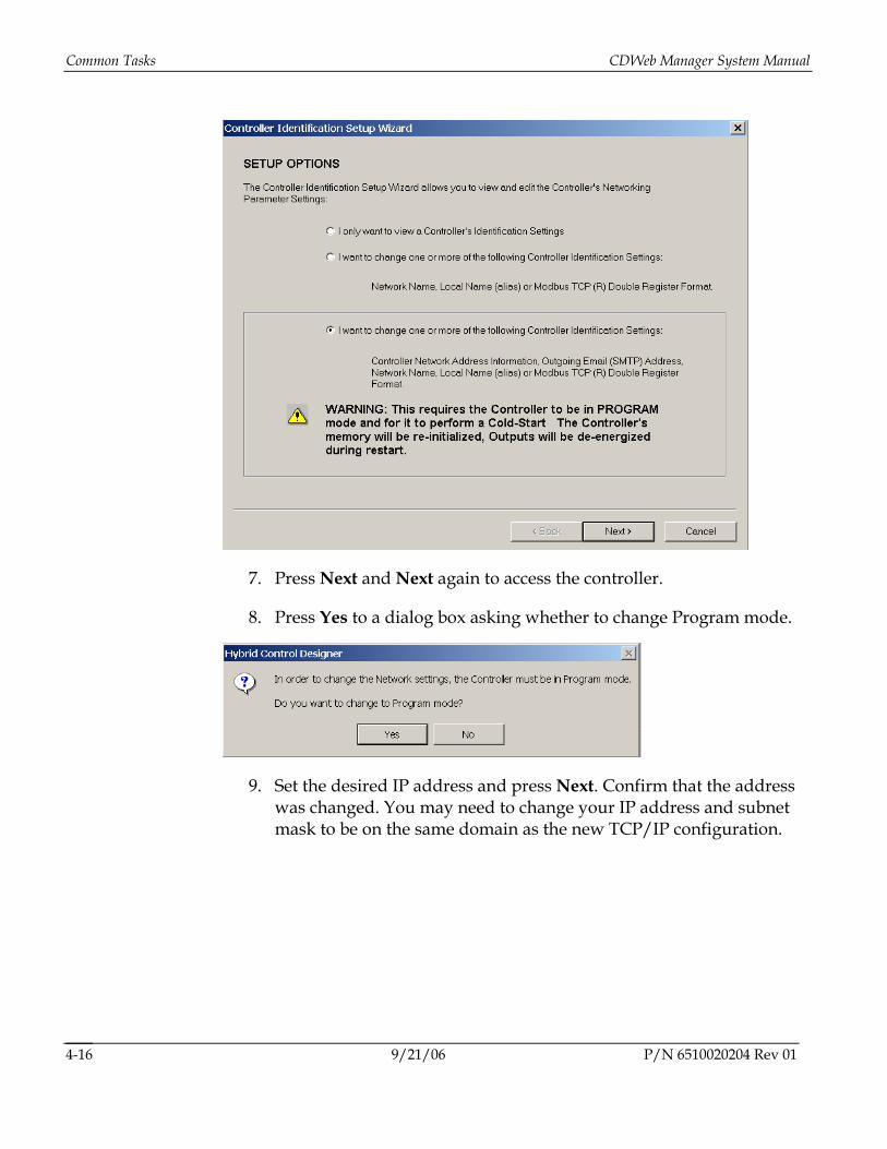
6. Select the third setup option allowing you to modify TCP/IP settings.
P/N 6510020204 Rev 01 9/21/06 4-15
Common Tasks CDWeb Manager System Manual
7. Press Next and Next again to access the controller.
8. Press Yes to a dialog box asking whether to change Program mode.
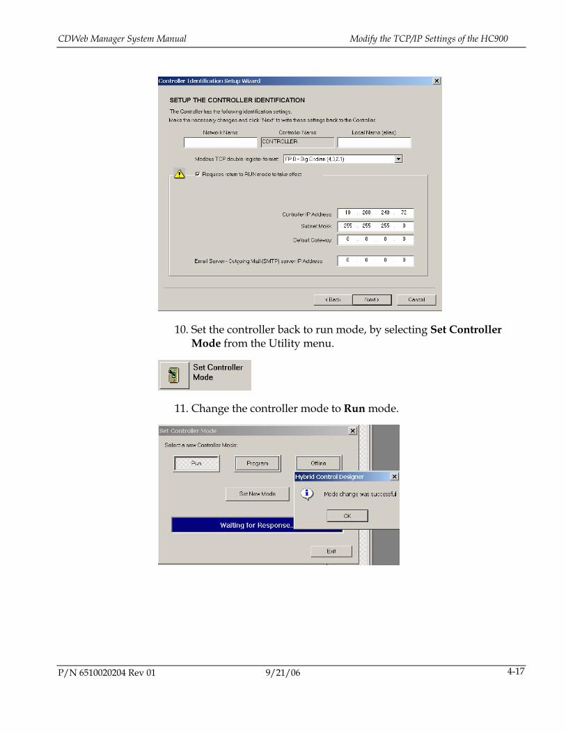
9. Set the desired IP address and press Next. Confirm that the address was changed. You may need to change your IP address and subnet mask to be on the same domain as the new TCP/IP configuration.
9/21/06 P/N 6510020204 Rev 01 4-16
CDWeb Manager System Manual Modify the TCP/IP Settings of the HC900
10. Set the controller back to run mode, by selecting Set Controller Mode from the Utility menu.
11. Change the controller mode to Run mode.
P/N 6510020204 Rev 01 9/21/06 4-17
Common Tasks CDWeb Manager System Manual
4.9. Create a Backup of HC900 Configuration and Logic
Before modifying interlock logic it is important to back up the existing logic. The following procedure lists the steps necessary for uploading the existing configuration to save as a backup. Perform this procedure before changing the HC900’s Logic:
1. Ensure that all configuration files have been closed. The Hybrid Control Designer window should be empty with no open windows.
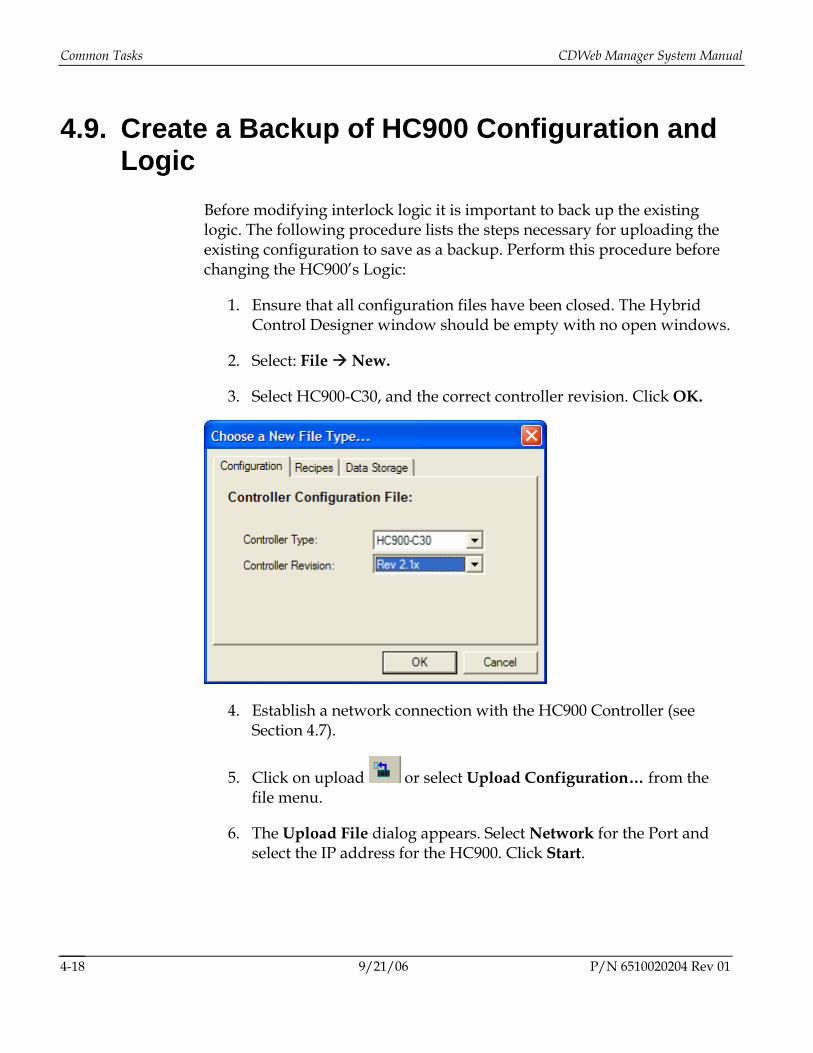
2. Select: File New.
3. Select HC900-C30, and the correct controller revision. Click OK.
4. Establish a network connection with the HC900 Controller (see Section 4.7).
5. Click on upload or select Upload Configuration… from the file menu.
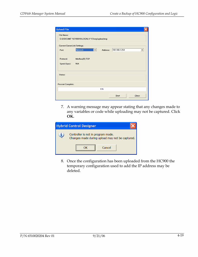
6. The Upload File dialog appears. Select Network for the Port and select the IP address for the HC900. Click Start.
9/21/06 P/N 6510020204 Rev 01 4-18
CDWeb Manager System Manual Create a Backup of HC900 Configuration and Logic
7. A warning message may appear stating that any changes made to any variables or code while uploading may not be captured. Click OK.
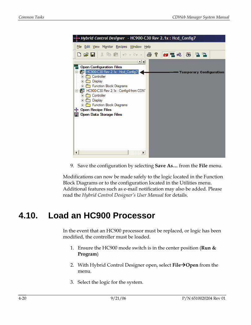
8. Once the configuration has been uploaded from the HC900 the temporary configuration used to add the IP address may be deleted.
P/N 6510020204 Rev 01 9/21/06 4-19
Common Tasks CDWeb Manager System Manual
9. Save the configuration by selecting Save As… from the File menu.
Modifications can now be made safely to the logic located in the Function Block Diagrams or to the configuration located in the Utilities menu. Additional features such as e-mail notification may also be added. Please read the Hybrid Control Designer’s User Manual for details.
4.10. Load an HC900 Processor In the event that an HC900 processor must be replaced, or logic has been modified, the controller must be loaded.
1. Ensure the HC900 mode switch is in the center position (Run & Program)
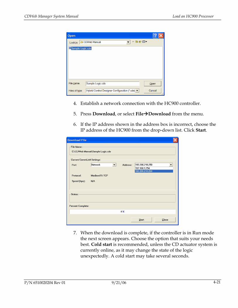
2. With Hybrid Control Designer open, select File Open from the menu.
3. Select the logic for the system.
9/21/06 P/N 6510020204 Rev 01 4-20
CDWeb Manager System Manual Load an HC900 Processor
4. Establish a network connection with the HC900 controller.
5. Press Download, or select File Download from the menu.
6. If the IP address shown in the address box is incorrect, choose the IP address of the HC900 from the drop-down list. Click Start.
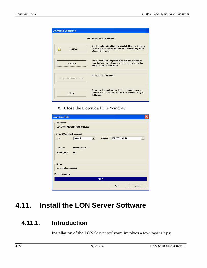
7. When the download is complete, if the controller is in Run mode the next screen appears. Choose the option that suits your needs best. Cold start is recommended, unless the CD actuator system is currently online, as it may change the state of the logic unexpectedly. A cold start may take several seconds.
P/N 6510020204 Rev 01 9/21/06 4-21
Common Tasks CDWeb Manager System Manual
8. Close the Download File Window.
4.11. Install the LON Server Software
4.11.1. Introduction Installation of the LON Server software involves a few basic steps:
9/21/06 P/N 6510020204 Rev 01 4-22
CDWeb Manager System Manual Install the LON Server Software
1. Installing the LON drivers
2. Creating the CDWeb profile
3. Adding the LON server
4. Setting up the HC900 communications
4.11.2. Installing the LON drivers Run the installation file OpenLDV210.exe and follow the on screen prompts, installing the files in their default directories.
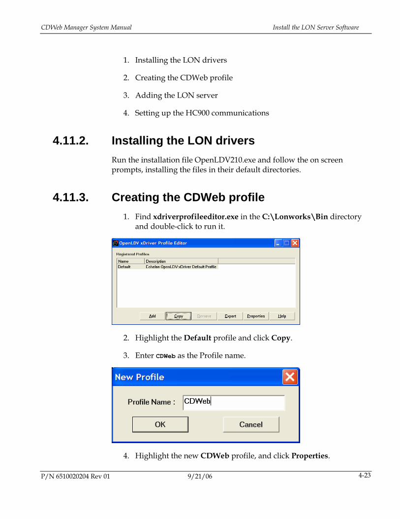
4.11.3. Creating the CDWeb profile 1. Find xdriverprofileeditor.exe in the C:\Lonworks\Bin directory
and double-click to run it.
2. Highlight the Default profile and click Copy.
3. Enter CDWeb as the Profile name.
4. Highlight the new CDWeb profile, and click Properties.
P/N 6510020204 Rev 01 9/21/06 4-23
Common Tasks CDWeb Manager System Manual
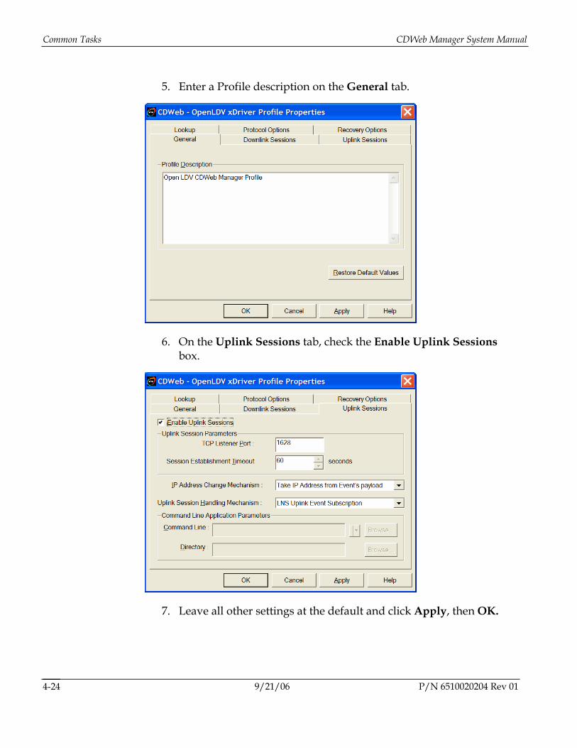
5. Enter a Profile description on the General tab.
6. On the Uplink Sessions tab, check the Enable Uplink Sessions box.
7. Leave all other settings at the default and click Apply, then OK.
9/21/06 P/N 6510020204 Rev 01 4-24
CDWeb Manager System Manual Install the LON Server Software
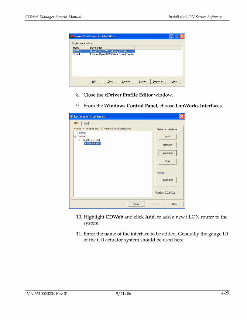
8. Close the xDriver Profile Editor window.
9. From the Windows Control Panel, choose LonWorks Interfaces.
10. Highlight CDWeb and click Add, to add a new i.LON router to the system.
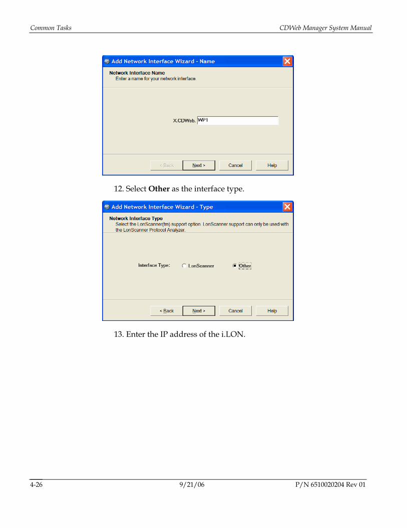
11. Enter the name of the interface to be added. Generally the gauge ID of the CD actuator system should be used here.
P/N 6510020204 Rev 01 9/21/06 4-25
Common Tasks CDWeb Manager System Manual
12. Select Other as the interface type.
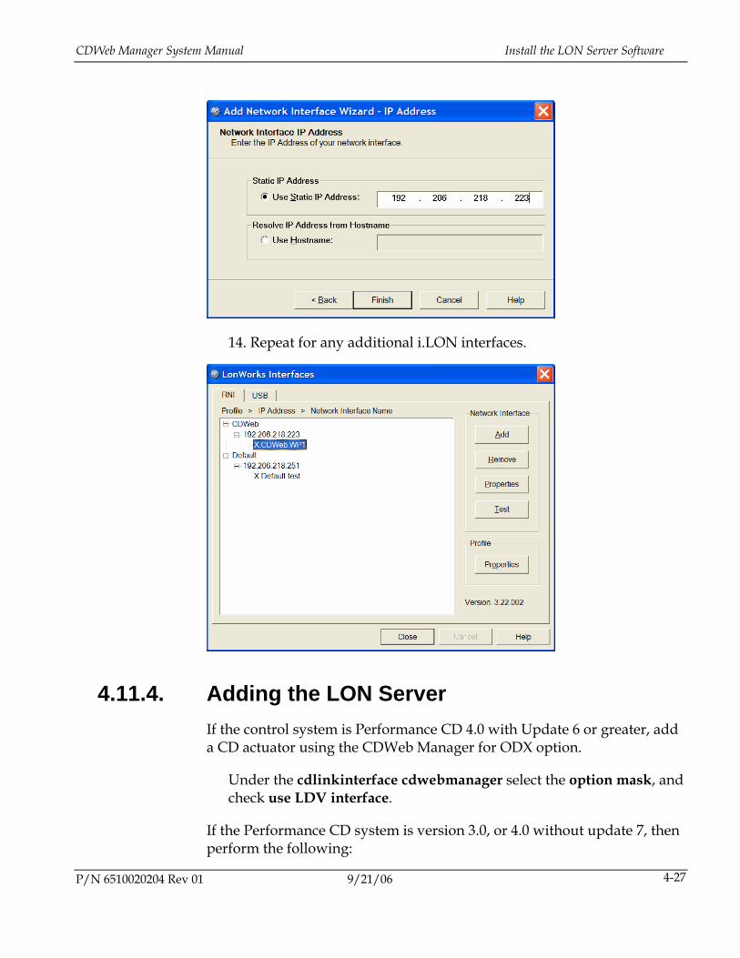
13. Enter the IP address of the i.LON.
9/21/06 P/N 6510020204 Rev 01 4-26
CDWeb Manager System Manual Install the LON Server Software
14. Repeat for any additional i.LON interfaces.
4.11.4. Adding the LON Server If the control system is Performance CD 4.0 with Update 6 or greater, add a CD actuator using the CDWeb Manager for ODX option.
Under the cdlinkinterface cdwebmanager select the option mask, and check use LDV interface.
If the Performance CD system is version 3.0, or 4.0 without update 7, then perform the following:
P/N 6510020204 Rev 01 9/21/06 4-27
Common Tasks CDWeb Manager System Manual
i
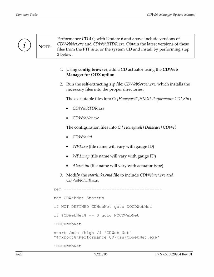
NOTE: Performance CD 4.0, with Update 6 and above include versions of CDWebNet.exe and CDWebRTDR.exe. Obtain the latest versions of these files from the FTP site, or the system CD and install by performing step 2 below.
1. Using config browser, add a CD actuator using the CDWeb Manager for ODX option.
2. Run the self-extracting zip file: CDWebServer.exe, which installs the necessary files into the proper directories.
The executable files into C:\Honeywell\HMX\Performance CD\Bin\
• CDWebRTDR.exe
• CDWebNet.exe
The configuration files into C:\Honeywell\Database\CDWeb
• CDWeb.ini
• WP1.csv (file name will vary with gauge ID)
• WP1.map (file name will vary with gauge ID)
• Alarm.ini (file name will vary with actuator type)
3. Modify the startlinks.cmd file to include CDWebnet.exe and CDWebRTDR.exe.
rem ---------------------------------------
rem CDWebNet Startup
if NOT DEFINED CDWebNet goto DOCDWebNet
if %CDWebNet% == 0 goto NOCDWebNet
:DOCDWebNet
start /min /high /i "CDWeb Net" "%mxroot%\Performance CD\bin\CDWebNet.exe"
:NOCDWebNet
9/21/06 P/N 6510020204 Rev 01 4-28
CDWeb Manager System Manual Install the LON Server Software
P/N 6510020204 Rev 01 9/21/06 4-29
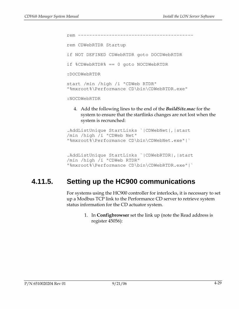
rem -----------------------------------------
rem CDWebRTDR Startup
if NOT DEFINED CDWebRTDR goto DOCDWebRTDR
if %CDWebRTDR% == 0 goto NOCDWebRTDR
:DOCDWebRTDR
start /min /high /i "CDWeb RTDR" "%mxroot%\Performance CD\bin\CDWebRTDR.exe"
:NOCDWebRTDR
4. Add the following lines to the end of the BuildSite.mac for the system to ensure that the startlinks changes are not lost when the system is recrunched:
.AddListUnique StartLinks `|CDWebNet|,|start /min /high /i "CDWeb Net" "%mxroot%\Performance CD\bin\CDWebNet.exe"|`
.AddListUnique StartLinks `|CDWebRTDR|,|start /min /high /i "CDWeb RTDR" "%mxroot%\Performance CD\bin\CDWebRTDR.exe"|`
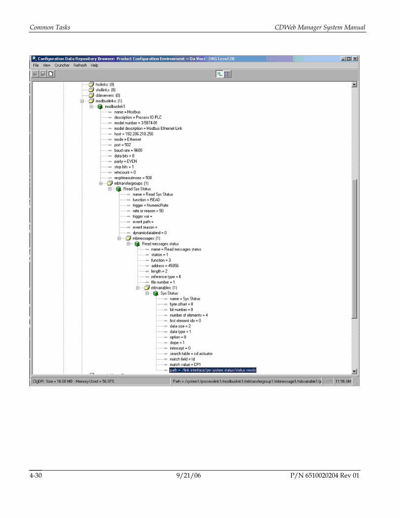
4.11.5. Setting up the HC900 communications For systems using the HC900 controller for interlocks, it is necessary to set up a Modbus TCP link to the Performance CD server to retrieve system status information for the CD actuator system.
1. In Configbrowser set the link up (note the Read address is register 45056):
Common Tasks CDWeb Manager System Manual
9/21/06 P/N 6510020204 Rev 01 4-30
CDWeb Manager System Manual Install the LON Server Software
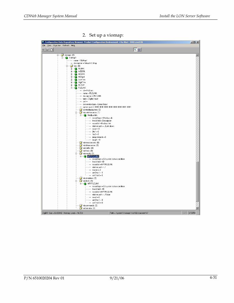
2. Set up a viomap:
P/N 6510020204 Rev 01 9/21/06 4-31
Common Tasks CDWeb Manager System Manual
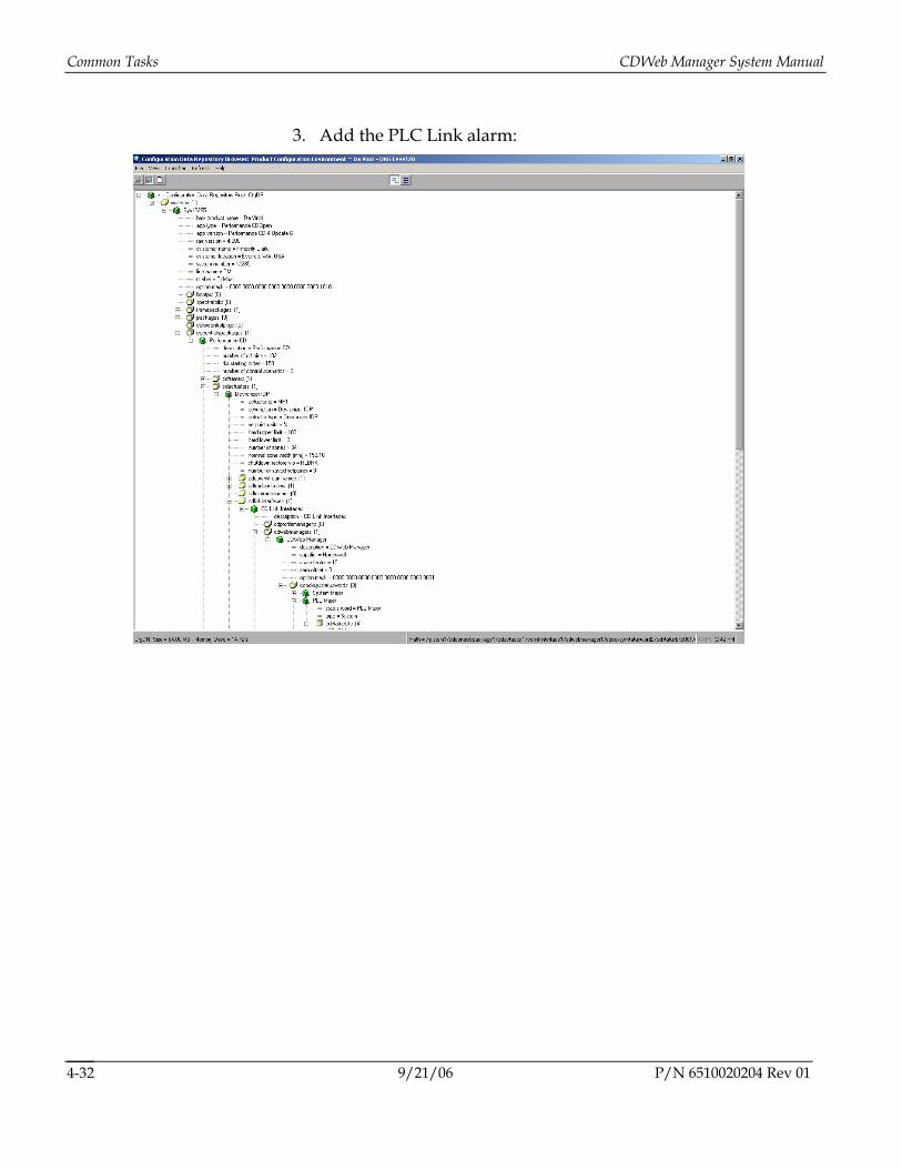
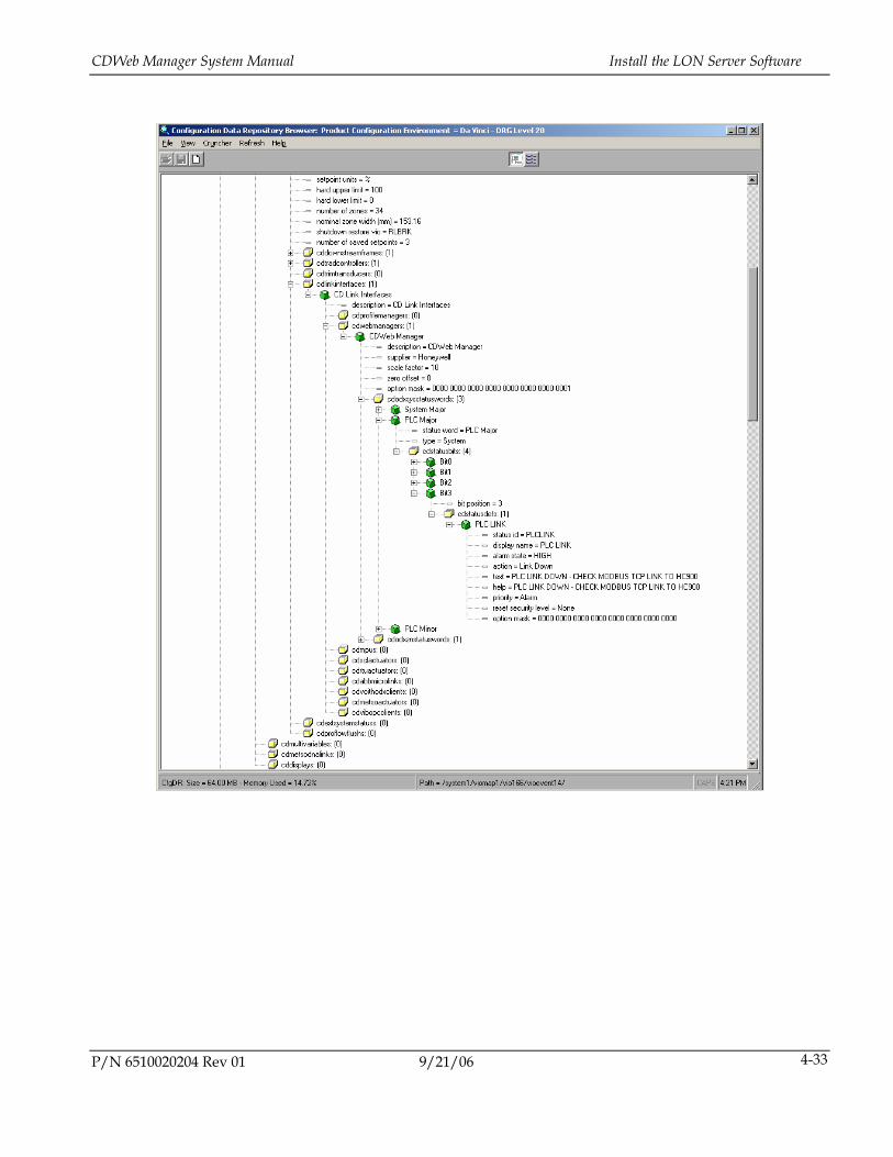
3. Add the PLC Link alarm:
9/21/06 P/N 6510020204 Rev 01 4-32
CDWeb Manager System Manual Install the LON Server Software
P/N 6510020204 Rev 01 9/21/06 4-33
Common Tasks CDWeb Manager System Manual
4.12. Modifying the CDWeb Processor IP Addresses
4.12.1. Remote Desktop Connection In order to make changes to the CDWeb Processor configuration, a keyboard, mouse, and monitor must be connected, or a Windows Remote Desktop connection must be established. Windows Remote Desktop is a standard feature in Windows XP Professional. It can also be added to earlier versions of Windows through a download from the Microsoft website.
To establish a Remote Desktop connection the the CDWeb Processor:
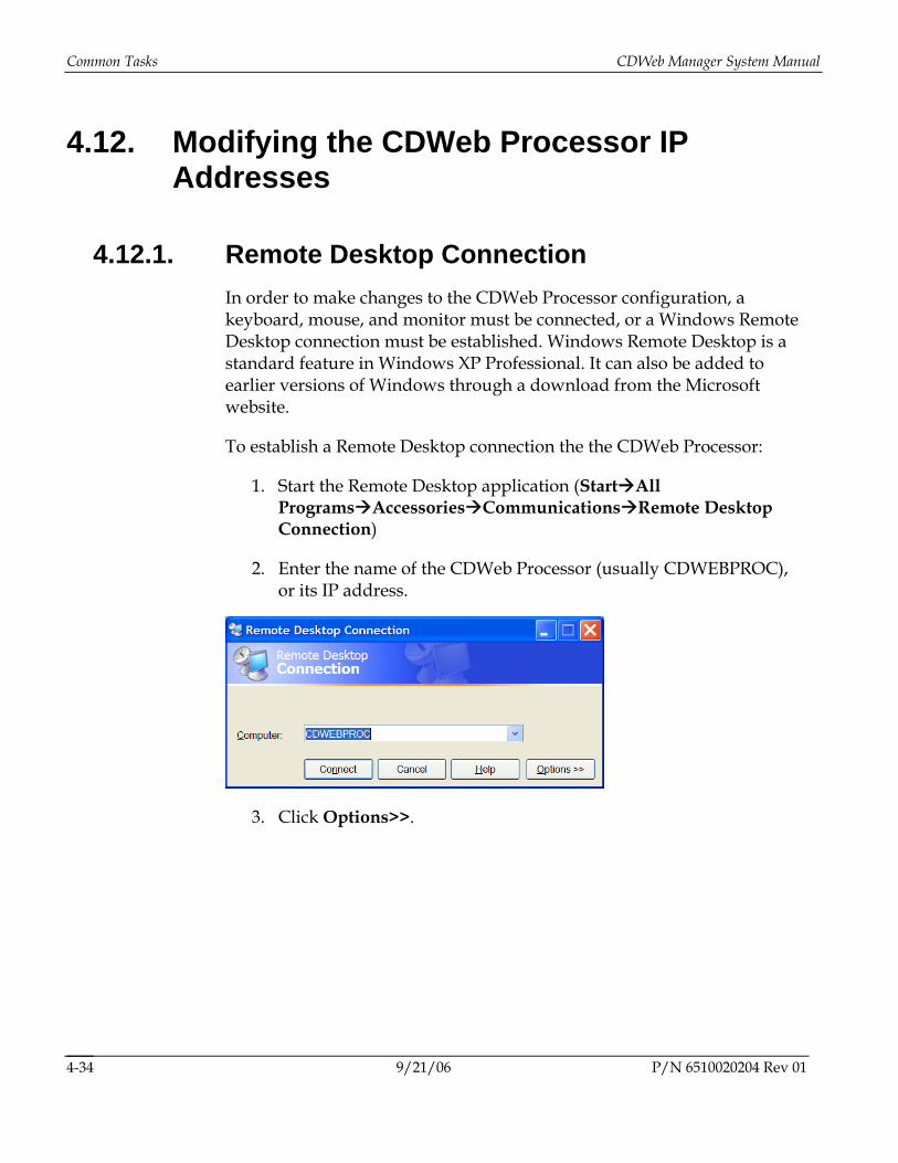
1. Start the Remote Desktop application (Start All Programs Accessories Communications Remote Desktop Connection)
2. Enter the name of the CDWeb Processor (usually CDWEBPROC), or its IP address.
3. Click Options>>.
9/21/06 P/N 6510020204 Rev 01 4-34
CDWeb Manager System Manual Modifying the CDWeb Processor IP Addresses
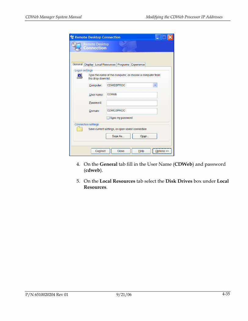
4. On the General tab fill in the User Name (CDWeb) and password (cdweb).
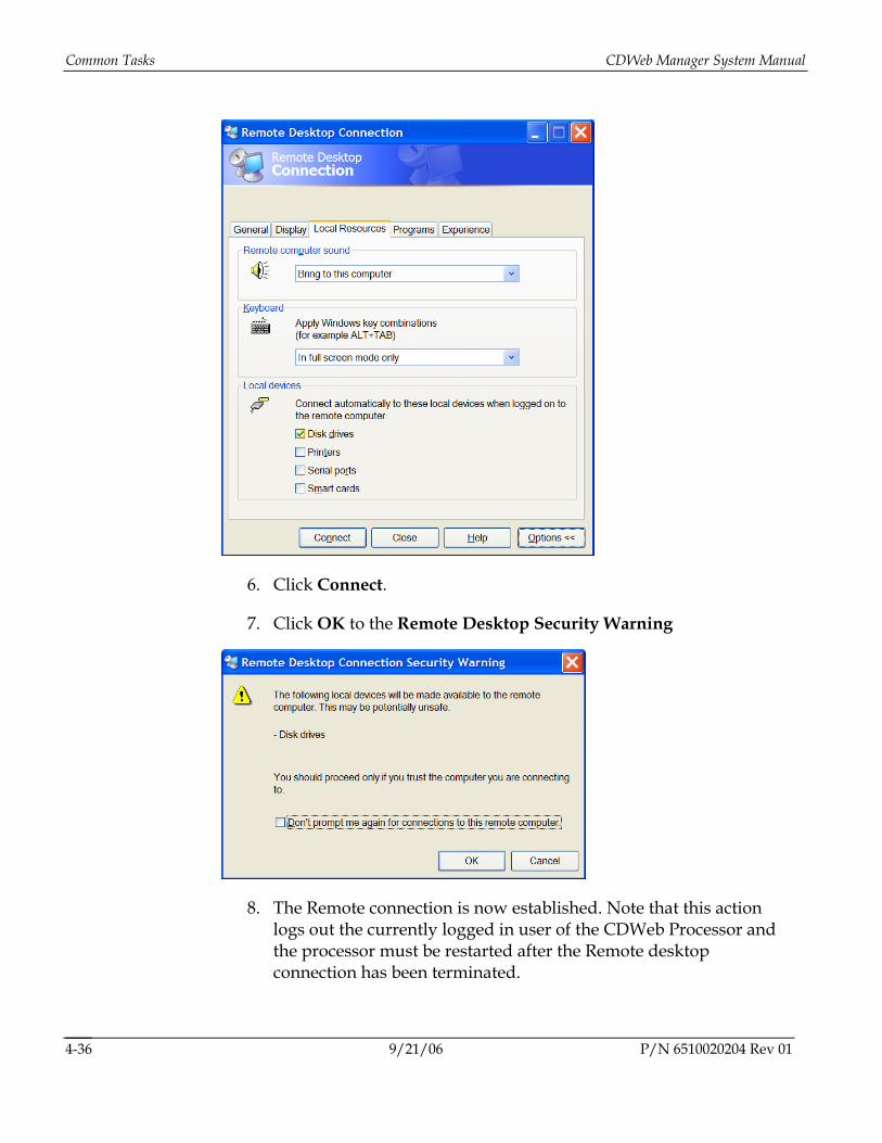
5. On the Local Resources tab select the Disk Drives box under Local Resources.
P/N 6510020204 Rev 01 9/21/06 4-35
Common Tasks CDWeb Manager System Manual
6. Click Connect.
7. Click OK to the Remote Desktop Security Warning
8. The Remote connection is now established. Note that this action logs out the currently logged in user of the CDWeb Processor and the processor must be restarted after the Remote desktop connection has been terminated.
9/21/06 P/N 6510020204 Rev 01 4-36
CDWeb Manager System Manual Modifying the CDWeb Processor IP Addresses
4.12.2. CDWeb Processor Address 1. Establish a Remote Desktop connection.
2. Using the Windows Control Panel set the computer’s IP address as you would with a standard Windows computer.
3. Restart the CDWeb Processor.
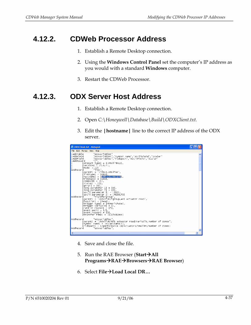
4.12.3. ODX Server Host Address 1. Establish a Remote Desktop connection.
2. Open C:\Honeywell\Database\Build\ODXClient.txt.
3. Edit the |hostname| line to the correct IP address of the ODX server.
4. Save and close the file.
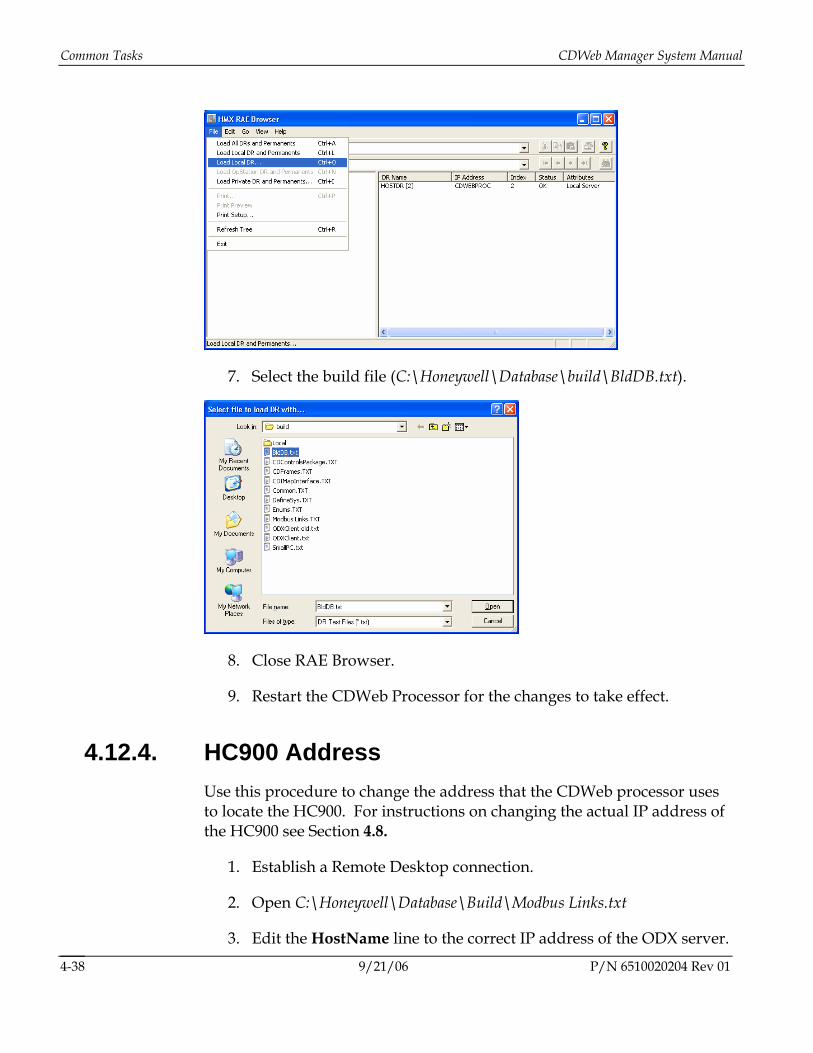
5. Run the RAE Browser (Start All Programs RAE Browsers RAE Browser)
6. Select File Load Local DR…
P/N 6510020204 Rev 01 9/21/06 4-37
Common Tasks CDWeb Manager System Manual
7. Select the build file (C:\Honeywell\Database\build\BldDB.txt).
8. Close RAE Browser.
9. Restart the CDWeb Processor for the changes to take effect.
4.12.4. HC900 Address Use this procedure to change the address that the CDWeb processor uses to locate the HC900. For instructions on changing the actual IP address of the HC900 see Section 4.8.
1. Establish a Remote Desktop connection.
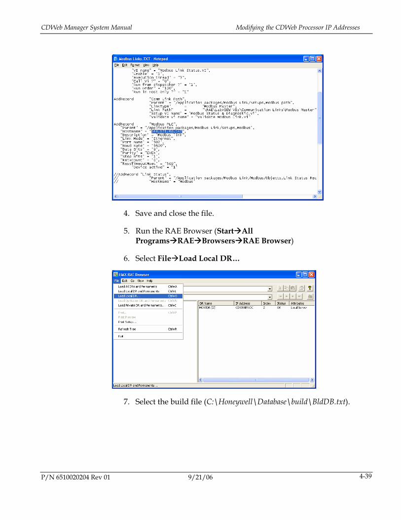
2. Open C:\Honeywell\Database\Build\Modbus Links.txt
3. Edit the HostName line to the correct IP address of the ODX server.
9/21/06 P/N 6510020204 Rev 01 4-38
CDWeb Manager System Manual Modifying the CDWeb Processor IP Addresses
4. Save and close the file.
5. Run the RAE Browser (Start All Programs RAE Browsers RAE Browser)
6. Select File Load Local DR…
7. Select the build file (C:\Honeywell\Database\build\BldDB.txt).
P/N 6510020204 Rev 01 9/21/06 4-39

Common Tasks CDWeb Manager System Manual
8. Close RAE Browser
9. Restart the CDWeb Processor for the changes to take effect.
4.12.5. i.LON Address Use this procedure to change the address that the CDWeb Processor, or DaVinci server, uses to communicate to the i.LON. To change the actual IP address of the i.LON see Section 4.5.
1. Establish a Remote Desktop connection to the CDWeb Processor. If the CDWeb Processor is not present and you are working on the DaVinci server, skip this step.
2. From the Windows Control Panel, choose LonWorks Interfaces.
9/21/06 P/N 6510020204 Rev 01 4-40
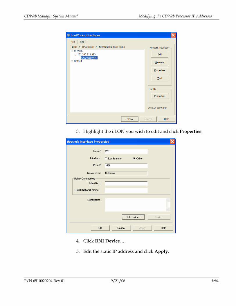
CDWeb Manager System Manual Modifying the CDWeb Processor IP Addresses
3. Highlight the i.LON you wish to edit and click Properties.
4. Click RNI Device….
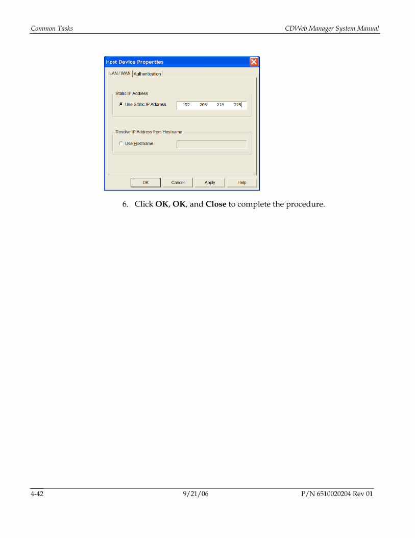
5. Edit the static IP address and click Apply.
P/N 6510020204 Rev 01 9/21/06 4-41
Common Tasks CDWeb Manager System Manual
6. Click OK, OK, and Close to complete the procedure.
9/21/06 P/N 6510020204 Rev 01 4-42
6510020204 Rev 01 5-1
5. Glossary
Actuator Mechanical or electronic device that performs the control action in a control loop.
CD Cross Direction
Used to refer to those properties of a process measurement or control device that are determined by its position along a line that runs across the paper machine. The Cross Direction is transverse to the MD (Machine Direction) that relates to a position along the length of the paper machine.
Da Vinci A Quality Control System.
QCS Quality Control System
A computer system which manages the quality of the paper produced.
RAE Real-Time Application Environment
The system software used by Da Vinci QCS to manage data exchange between applications (with Performance CD being one of them).
RTDR Real-Time Data Repository
The database managed by RAE to store system data and data for individual applications.
Setpoint (SP) Target value (desired value). Setpoints are defined process values that can be modified by entering new values through the monitor, loading grade data, and changing a supervisory target.
VIO Virtual Input/Output

6510020204 Rev 01 A-1
A. CDWeb Configuration Files
To operate correctly, the CDWeb LON server applications (CDWebNet.exe and CDWebRTDR.exe) require configuration information in the form of several text-based files. This appendix provides a description of the contents of each of these files.
A.1.1. Actuator Alarm Enumeration Some configuration parameters reference the raw actuator alarms arriving as part of the actuator status messages. In these configuration files the alarm bits are enumerated right to left within every byte of raw actuator alarms. Bytes are used in their natural order, from left to right. This enumeration differs from all other systems currently used for actuator alarm documentation. For example, AutoSlice CDW alarm enumeration uses bits within bytes in the same sequence, but swaps every pair of bytes.
A.2. CDWeb.ini When CDWebNet.exe first starts, it searches for the CDWeb.ini file in the %MXRTDB%\CDWeb directory, where MXRTDB is a system environment variable normally set during the RAE installation process.
The CDWeb.ini file internally references the other configuration files by name, with paths included. If the other files are located in the same directory as CDWeb.ini, then no path information is required.
The structure of the file conforms to conventional Windows INI file format.
CDWeb Configuration Files CDWeb Manager System Manual
9/21/06 P/N 6510020204 Rev 01 A-2
• All names are not case sensitive
• Any number of spaces is allowed between keywords
• Parameter values containing spaces must be enclosed in double quotes
• Comments start with the semicolon character (;)
• Comments are allowed at the end of any line, or as a separate line.
The CDWeb.ini file consists of one or more INI sections. Each section name is enclosed in square brackets and corresponds to one LON interface.
Each INI file section has the following parameters defined:
A.2.1. host gauge Defines the symbol used to find CD Control profile related information in the RTDR database.
Example:
host gauge = CP1
A.2.2. actuator type [not currently used]
Defines the expected actuator type. This type must correspond to the type defined in the RTDR and the type reported by the actuator.
Example:
Actuator type = autosliceCDW
A.2.3. Number of actuators Defines the number of control zones in the CD control profile. This number must be the same as defined in the RTDR database.
CDWeb Manager System Manual CDWeb.ini
P/N 6510020204 Rev 01 9/21/06 A-3
Example:
Number of actuators = 65
A.2.4. Actuators per node Defines the number of actuator per node on the LON network. For most actuator types this number is 1, however, the IDP actuator uses 8 actuators per node.
Example:
Actuators per node = 8 ; IDP actuator
A.2.5. Interlock Mask Defines the condition when “set interlock command” is sent to the actuators and is used only for actuators that support interlocks. The mask is defined as a 16 bit word used to check bits in the system status word located in the RTDR database. It can be presented in two formats: as a binary string, or as a hexadecimal constant. This parameter is optional, with a default value of zero (no interlocks).
A.2.6. Setpoint/position send mask Defines the conditions under which the RTDR database receives actuator setpoints instead of actual positions. The mask is defined as a 16 bit word used to check bits in the system status word located in the RTDR database and can be presented as a binary string or as a hexadecimal constant. This parameter is optional, and the default value is zero (always send positions).
Examples:
Setpoint/position send mask = 0000010100010100 ; binary string
Setpoint/position send mask = 0x0514; hexadecimal constant
CDWeb Configuration Files CDWeb Manager System Manual
9/21/06 P/N 6510020204 Rev 01 A-4
A.2.7. Powerup bit Defines the bit number in the raw actuator alarms used as the “power up” flag. This bit is checked every time a status message arrives from an actuator. This parameter is optional, with a default value of 255 (powerup bit is not used).
Example:
Powerup bit = 40; Calcoil CW actuator power up bit
A.2.8. Powerup reset bit Defines the bit number to put in the reset command for the powerup bit. This number is different from the powerup bit because of different systems of actuator alarm enumeration.
This parameter is optional, but must be present if powerup bit is defined.
Example:
Powerup reset bit = 1 ; Calcoil CW
A.2.9. Flushable Defines if the actuator supports flushing sequences. Can be defined as 0 (default, non-flushable), or 1 (flushable).
Example:
Flushable = 0
A.2.10. Database Defines the name, and optionally the location, of the LON network configuration file.
Example:
Database = export.csv
CDWeb Manager System Manual CDWeb.ini
P/N 6510020204 Rev 01 9/21/06 A-5
A.2.11. Node name Defines the name of the host node (i.LON) in the database file. It is used for extraction of the host node address and the bound network variables.
Example:
Node name = cdweb_proc_1; standard name for the host node
A.2.12. Beam id Defines the ID number of the CD actuator system within the database file. One database file can contain configuration for several CD actuator systems.
Example:
Beam id = 1
A.2.13. Actuator map file Defines the name, and optionally the location, of the file containing the zone mapping information.
Example:
Actuator map file = zone.map
A.2.14. Alarm map file Defines the name of the file containing the actuator alarm mapping configuration.
Example:
Alarm map file = alrmsAutosliceCDW.ini
CDWeb Configuration Files CDWeb Manager System Manual
9/21/06 P/N 6510020204 Rev 01 A-6
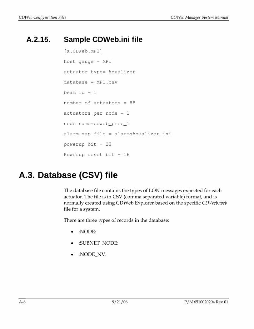
A.2.15. Sample CDWeb.ini file [X.CDWeb.MP1]
host gauge = MP1
actuator type= Aqualizer
database = MP1.csv
beam id = 1
number of actuators = 88
actuators per node = 1
node name=cdweb_proc_1
alarm map file = alarmsAqualizer.ini
powerup bit = 23
Powerup reset bit = 16
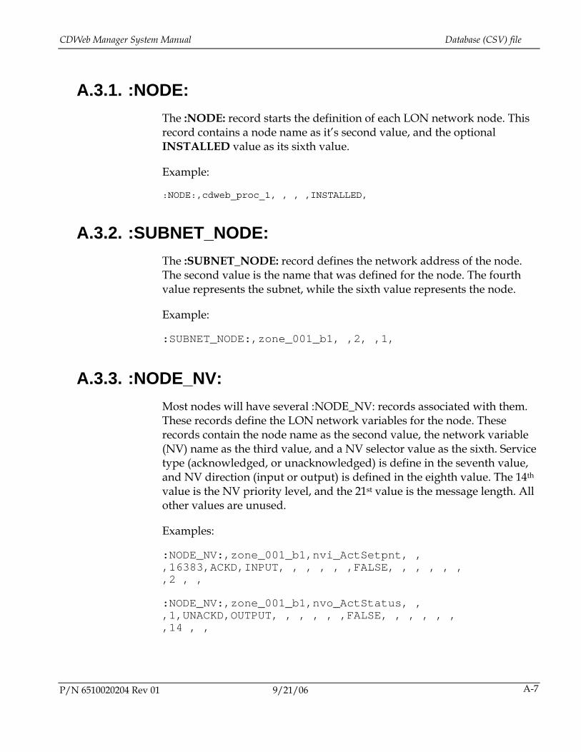
A.3. Database (CSV) file The database file contains the types of LON messages expected for each actuator. The file is in CSV (comma separated variable) format, and is normally created using CDWeb Explorer based on the specific CDWeb.web file for a system.
There are three types of records in the database:
• :NODE:
• :SUBNET_NODE:
• :NODE_NV:
CDWeb Manager System Manual Database (CSV) file
P/N 6510020204 Rev 01 9/21/06 A-7
A.3.1. :NODE: The :NODE: record starts the definition of each LON network node. This record contains a node name as it’s second value, and the optional INSTALLED value as its sixth value.
Example:
:NODE:,cdweb_proc_1, , , ,INSTALLED,
A.3.2. :SUBNET_NODE: The :SUBNET_NODE: record defines the network address of the node. The second value is the name that was defined for the node. The fourth value represents the subnet, while the sixth value represents the node.
Example:
:SUBNET_NODE:,zone_001_b1, ,2, ,1,
A.3.3. :NODE_NV: Most nodes will have several :NODE_NV: records associated with them. These records define the LON network variables for the node. These records contain the node name as the second value, the network variable (NV) name as the third value, and a NV selector value as the sixth. Service type (acknowledged, or unacknowledged) is define in the seventh value, and NV direction (input or output) is defined in the eighth value. The 14th value is the NV priority level, and the 21st value is the message length. All other values are unused.
Examples:
:NODE_NV:,zone_001_b1,nvi_ActSetpnt, , ,16383,ACKD,INPUT, , , , , ,FALSE, , , , , , ,2 , ,
:NODE_NV:,zone_001_b1,nvo_ActStatus, , ,1,UNACKD,OUTPUT, , , , , ,FALSE, , , , , , ,14 , ,
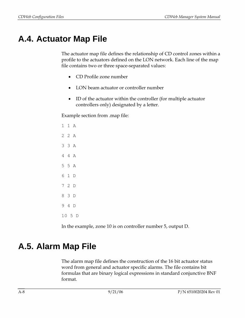
CDWeb Configuration Files CDWeb Manager System Manual
9/21/06 P/N 6510020204 Rev 01 A-8
A.4. Actuator Map File The actuator map file defines the relationship of CD control zones within a profile to the actuators defined on the LON network. Each line of the map file contains two or three space-separated values:
• CD Profile zone number
• LON beam actuator or controller number
• ID of the actuator within the controller (for multiple actuator controllers only) designated by a letter.
Example section from .map file:
1 1 A
2 2 A
3 3 A
4 4 A
5 5 A
6 1 D
7 2 D
8 3 D
9 4 D
10 5 D
In the example, zone 10 is on controller number 5, output D.
A.5. Alarm Map File The alarm map file defines the construction of the 16 bit actuator status word from general and actuator specific alarms. The file contains bit formulas that are binary logical expressions in standard conjunctive BNF format.
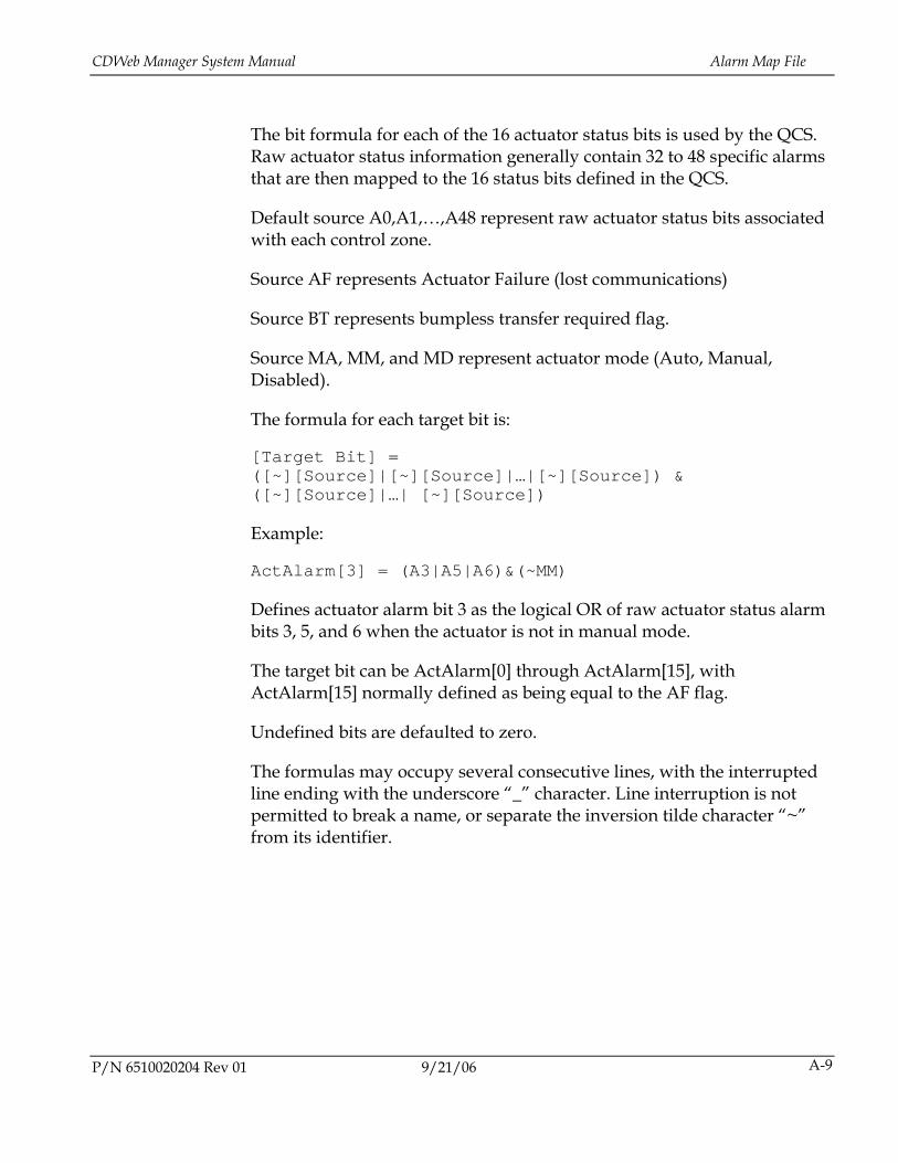
CDWeb Manager System Manual Alarm Map File
P/N 6510020204 Rev 01 9/21/06 A-9
The bit formula for each of the 16 actuator status bits is used by the QCS. Raw actuator status information generally contain 32 to 48 specific alarms that are then mapped to the 16 status bits defined in the QCS.
Default source A0,A1,…,A48 represent raw actuator status bits associated with each control zone.
Source AF represents Actuator Failure (lost communications)
Source BT represents bumpless transfer required flag.
Source MA, MM, and MD represent actuator mode (Auto, Manual, Disabled).
The formula for each target bit is:
[Target Bit] = ([~][Source]|[~][Source]|…|[~][Source]) & ([~][Source]|…| [~][Source])
Example:
ActAlarm[3] = (A3|A5|A6)&(~MM)
Defines actuator alarm bit 3 as the logical OR of raw actuator status alarm bits 3, 5, and 6 when the actuator is not in manual mode.
The target bit can be ActAlarm[0] through ActAlarm[15], with ActAlarm[15] normally defined as being equal to the AF flag.
Undefined bits are defaulted to zero.
The formulas may occupy several consecutive lines, with the interrupted line ending with the underscore “_” character. Line interruption is not permitted to break a name, or separate the inversion tilde character “~” from its identifier.

6510020204 Rev 01 B-1
B. System and Actuator Alarms
This appendix outlines the system alarms and actuator alarms that may appear on operator displays.
B.1. System Alarms Interlocks represent conditions that must be satisfied in order for the actuator system to safely and accurately operate. These conditions are defined in terms of digital and/or analog signals provided by related systems or instruments to the optional I/O subsystem in the CDWeb Manager cabinet. The CDWeb Processor organizes the information from the I/O subsystem as four status words, with each word 16 bits in size, for re-transmission to the host system.
For systems that do not require interlocks, or where the interlocks are handled by another means, the system status words will be unused except for Not Ready For Control or Waiting For Actuator Startup.
B.2. Actuator Alarms Individual actuators have either 32 bit or 48 status words; the CDWeb Manager application summarizes these actuator alarms into one 16-bit word per actuator for use by the QCS.
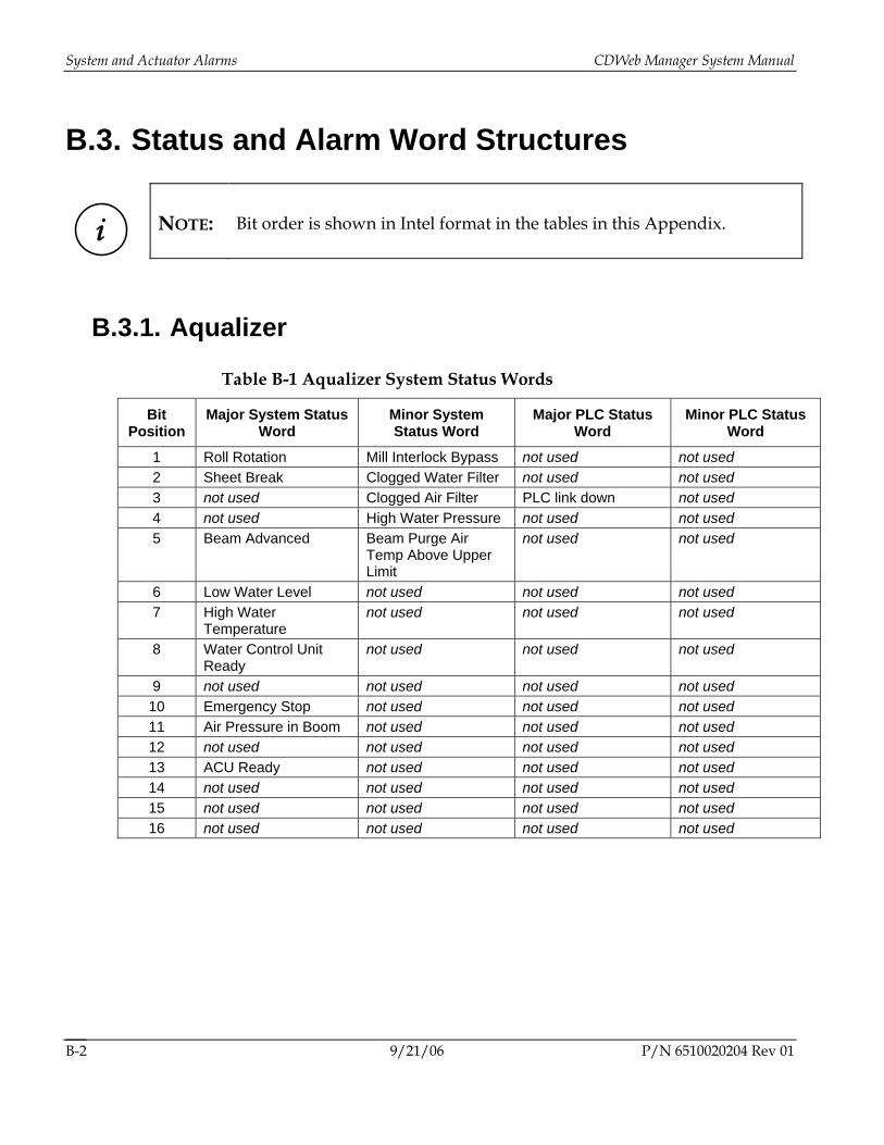
System and Actuator Alarms CDWeb Manager System Manual
B.3. Status and Alarm Word Structures
i
NOTE: Bit order is shown in Intel format in the tables in this Appendix.
B.3.1. Aqualizer
Table B-1 Aqualizer System Status Words
Bit Position
Major System Status Word
Minor System Status Word
Major PLC Status Word
Minor PLC Status Word
1 Roll Rotation Mill Interlock Bypass not used not used 2 Sheet Break Clogged Water Filter not used not used 3 not used Clogged Air Filter PLC link down not used 4 not used High Water Pressure not used not used 5 Beam Advanced Beam Purge Air
Temp Above Upper Limit
not used not used
6 Low Water Level not used not used not used 7 High Water
Temperature not used not used not used
8 Water Control Unit Ready
not used not used not used
9 not used not used not used not used 10 Emergency Stop not used not used not used 11 Air Pressure in Boom not used not used not used 12 not used not used not used not used 13 ACU Ready not used not used not used 14 not used not used not used not used 15 not used not used not used not used 16 not used not used not used not used
9/21/06 P/N 6510020204 Rev 01 B-2
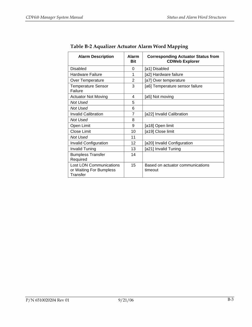
CDWeb Manager System Manual Status and Alarm Word Structures
P/N 6510020204 Rev 01 9/21/06 B-3
Table B-2 Aqualizer Actuator Alarm Word Mapping
Alarm Description Alarm Bit
Corresponding Actuator Status from CDWeb Explorer
Disabled 0 [a1] Disabled Hardware Failure 1 [a2] Hardware failure Over Temperature 2 [a7] Over temperature Temperature Sensor Failure
3 [a6] Temperature sensor failure
Actuator Not Moving 4 [a5] Not moving Not Used 5 Not Used 6 Invalid Calibration 7 [a22] Invalid Calibration Not Used 8 Open Limit 9 [a18] Open limit Close Limit 10 [a19] Close limit Not Used 11 Invalid Configuration 12 [a20] Invalid Configuration Invalid Tuning 13 [a21] Invalid Tuning Bumpless Transfer Required
14
Lost LON Communications or Waiting For Bumpless Transfer
15 Based on actuator communications timeout
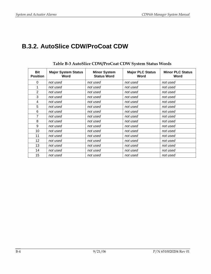
System and Actuator Alarms CDWeb Manager System Manual
9/21/06 P/N 6510020204 Rev 01 B-4
B.3.2. AutoSlice CDW/ProCoat CDW
Table B-3 AutoSlice CDW/ProCoat CDW System Status Words
Bit Position
Major System Status Word
Minor System Status Word
Major PLC Status Word
Minor PLC Status Word
0 not used not used not used not used 1 not used not used not used not used 2 not used not used not used not used 3 not used not used not used not used 4 not used not used not used not used 5 not used not used not used not used 6 not used not used not used not used 7 not used not used not used not used 8 not used not used not used not used 9 not used not used not used not used 10 not used not used not used not used 11 not used not used not used not used 12 not used not used not used not used 13 not used not used not used not used 14 not used not used not used not used 15 not used not used not used not used
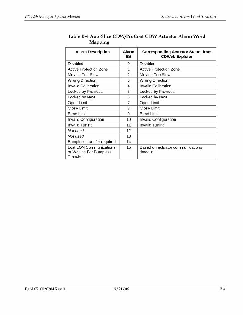
CDWeb Manager System Manual Status and Alarm Word Structures
P/N 6510020204 Rev 01 9/21/06 B-5
Table B-4 AutoSlice CDW/ProCoat CDW Actuator Alarm Word Mapping
Alarm Description Alarm Bit
Corresponding Actuator Status from CDWeb Explorer
Disabled 0 Disabled Active Protection Zone 1 Active Protection Zone Moving Too Slow 2 Moving Too Slow Wrong Direction 3 Wrong Direction Invalid Calibration 4 Invalid Calibration Locked by Previous 5 Locked by Previous Locked by Next 6 Locked by Next Open Limit 7 Open Limit Close Limit 8 Close Limit Bend Limit 9 Bend Limit Invalid Configuration 10 Invalid Configuration Invalid Tuning 11 Invalid Tuning Not used 12 Not used 13 Bumpless transfer required 14 Lost LON Communications or Waiting For Bumpless Transfer
15 Based on actuator communications timeout
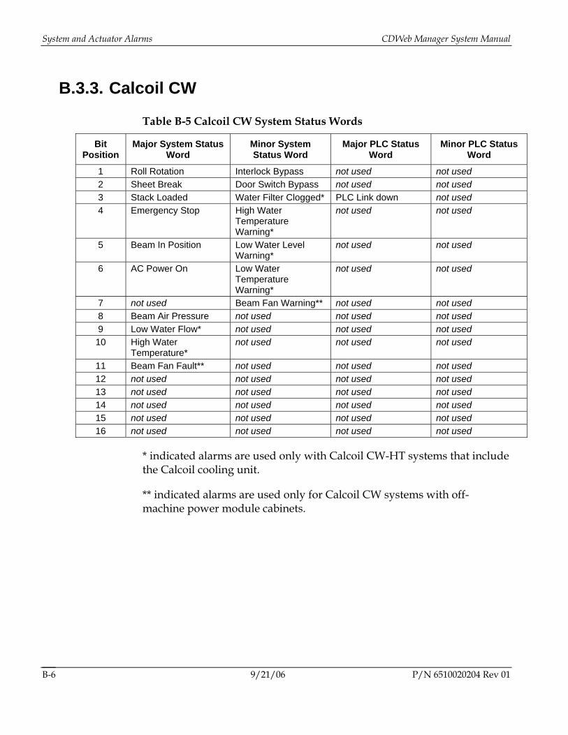
System and Actuator Alarms CDWeb Manager System Manual
9/21/06 P/N 6510020204 Rev 01 B-6
B.3.3. Calcoil CW
Table B-5 Calcoil CW System Status Words
Bit Position
Major System Status Word
Minor System Status Word
Major PLC Status Word
Minor PLC Status Word
1 Roll Rotation Interlock Bypass not used not used 2 Sheet Break Door Switch Bypass not used not used 3 Stack Loaded Water Filter Clogged* PLC Link down not used 4 Emergency Stop High Water
Temperature Warning*
not used not used
5 Beam In Position Low Water Level Warning*
not used not used
6 AC Power On Low Water Temperature Warning*
not used not used
7 not used Beam Fan Warning** not used not used 8 Beam Air Pressure not used not used not used 9 Low Water Flow* not used not used not used 10 High Water
Temperature* not used not used not used
11 Beam Fan Fault** not used not used not used 12 not used not used not used not used 13 not used not used not used not used 14 not used not used not used not used 15 not used not used not used not used 16 not used not used not used not used
* indicated alarms are used only with Calcoil CW-HT systems that include the Calcoil cooling unit.
** indicated alarms are used only for Calcoil CW systems with off-machine power module cabinets.
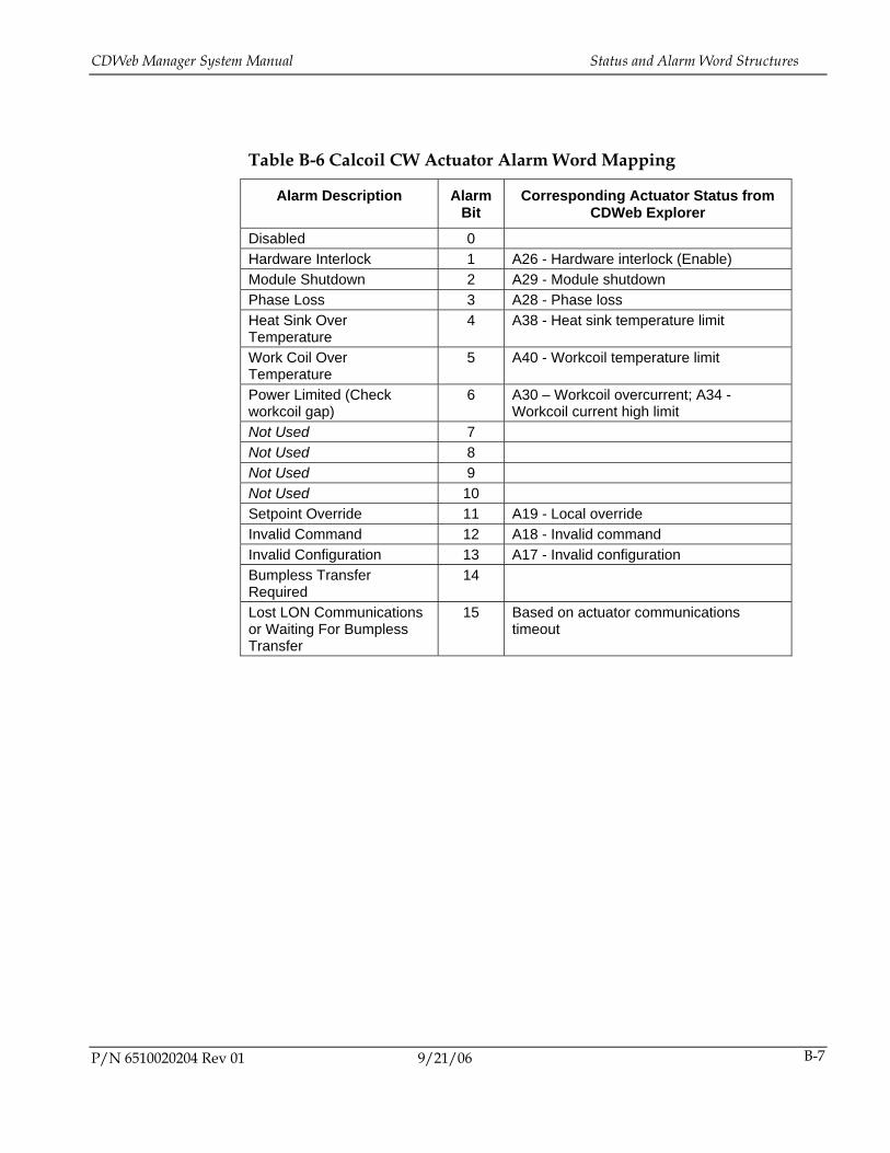
CDWeb Manager System Manual Status and Alarm Word Structures
P/N 6510020204 Rev 01 9/21/06 B-7
Table B-6 Calcoil CW Actuator Alarm Word Mapping
Alarm Description Alarm Bit
Corresponding Actuator Status from CDWeb Explorer
Disabled 0 Hardware Interlock 1 A26 - Hardware interlock (Enable) Module Shutdown 2 A29 - Module shutdown Phase Loss 3 A28 - Phase loss Heat Sink Over Temperature
4 A38 - Heat sink temperature limit
Work Coil Over Temperature
5 A40 - Workcoil temperature limit
Power Limited (Check workcoil gap)
6 A30 – Workcoil overcurrent; A34 - Workcoil current high limit
Not Used 7 Not Used 8 Not Used 9 Not Used 10 Setpoint Override 11 A19 - Local override Invalid Command 12 A18 - Invalid command Invalid Configuration 13 A17 - Invalid configuration Bumpless Transfer Required
14
Lost LON Communications or Waiting For Bumpless Transfer
15 Based on actuator communications timeout
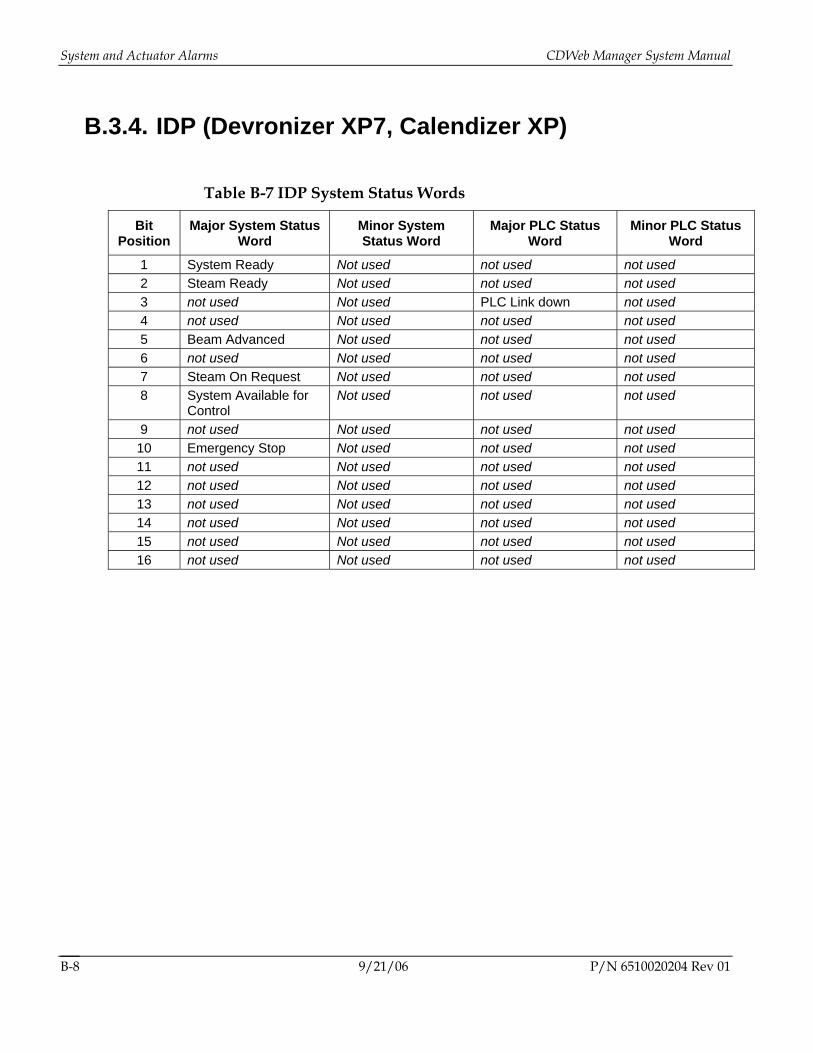
System and Actuator Alarms CDWeb Manager System Manual
9/21/06 P/N 6510020204 Rev 01 B-8
B.3.4. IDP (Devronizer XP7, Calendizer XP)
Table B-7 IDP System Status Words
Bit Position
Major System Status Word
Minor System Status Word
Major PLC Status Word
Minor PLC Status Word
1 System Ready Not used not used not used 2 Steam Ready Not used not used not used 3 not used Not used PLC Link down not used 4 not used Not used not used not used 5 Beam Advanced Not used not used not used 6 not used Not used not used not used 7 Steam On Request Not used not used not used 8 System Available for
Control Not used not used not used
9 not used Not used not used not used 10 Emergency Stop Not used not used not used 11 not used Not used not used not used 12 not used Not used not used not used 13 not used Not used not used not used 14 not used Not used not used not used 15 not used Not used not used not used 16 not used Not used not used not used
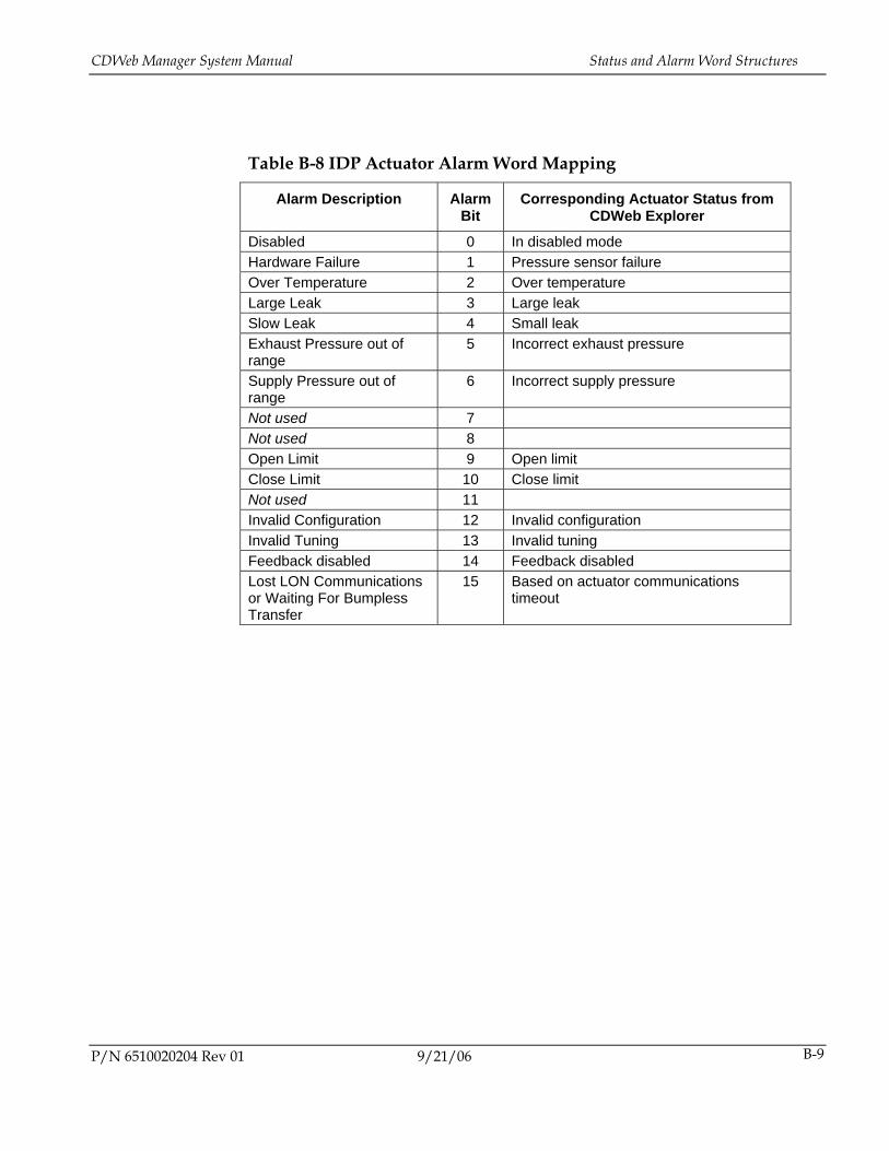
CDWeb Manager System Manual Status and Alarm Word Structures
P/N 6510020204 Rev 01 9/21/06 B-9
Table B-8 IDP Actuator Alarm Word Mapping
Alarm Description Alarm Bit
Corresponding Actuator Status from CDWeb Explorer
Disabled 0 In disabled mode Hardware Failure 1 Pressure sensor failure Over Temperature 2 Over temperature Large Leak 3 Large leak Slow Leak 4 Small leak Exhaust Pressure out of range
5 Incorrect exhaust pressure
Supply Pressure out of range
6 Incorrect supply pressure
Not used 7 Not used 8 Open Limit 9 Open limit Close Limit 10 Close limit Not used 11 Invalid Configuration 12 Invalid configuration Invalid Tuning 13 Invalid tuning Feedback disabled 14 Feedback disabled Lost LON Communications or Waiting For Bumpless Transfer
15 Based on actuator communications timeout
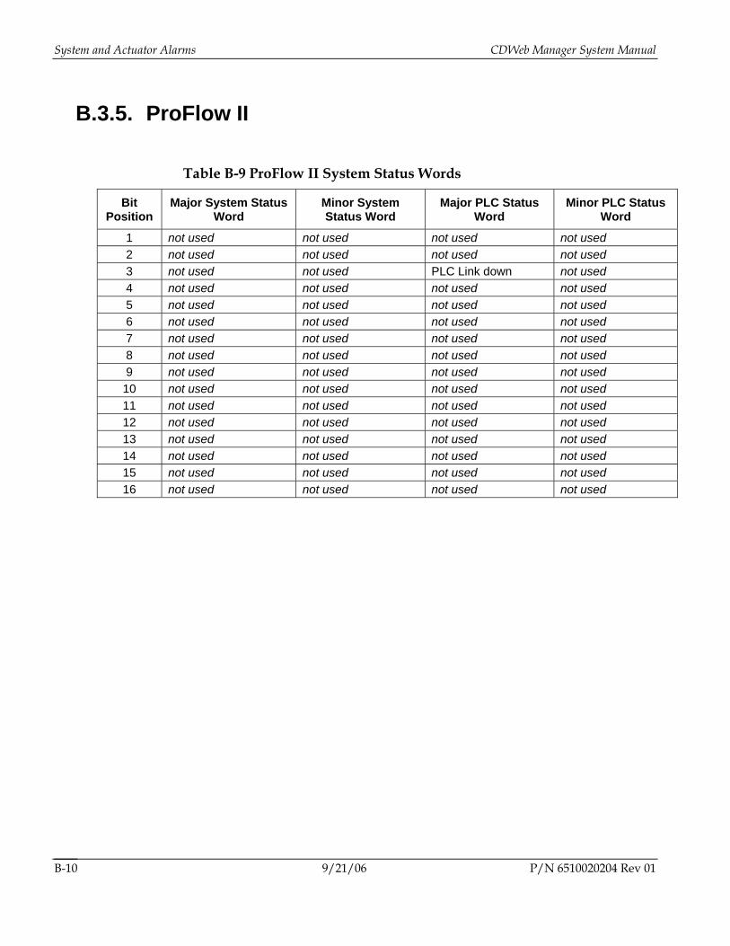
System and Actuator Alarms CDWeb Manager System Manual
9/21/06 P/N 6510020204 Rev 01 B-10
B.3.5. ProFlow II
Table B-9 ProFlow II System Status Words
Bit Position
Major System Status Word
Minor System Status Word
Major PLC Status Word
Minor PLC Status Word
1 not used not used not used not used 2 not used not used not used not used 3 not used not used PLC Link down not used 4 not used not used not used not used 5 not used not used not used not used 6 not used not used not used not used 7 not used not used not used not used 8 not used not used not used not used 9 not used not used not used not used 10 not used not used not used not used 11 not used not used not used not used 12 not used not used not used not used 13 not used not used not used not used 14 not used not used not used not used 15 not used not used not used not used 16 not used not used not used not used
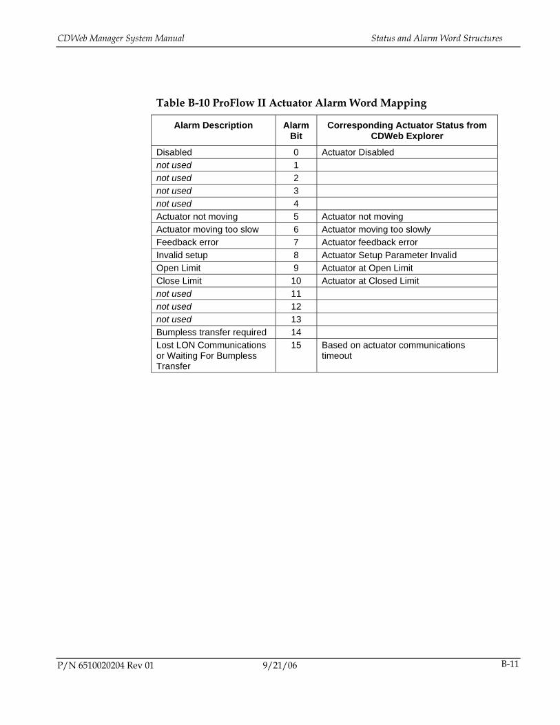
CDWeb Manager System Manual Status and Alarm Word Structures
P/N 6510020204 Rev 01 9/21/06 B-11
Table B-10 ProFlow II Actuator Alarm Word Mapping
Alarm Description Alarm Bit
Corresponding Actuator Status from CDWeb Explorer
Disabled 0 Actuator Disabled not used 1 not used 2 not used 3 not used 4 Actuator not moving 5 Actuator not moving Actuator moving too slow 6 Actuator moving too slowly Feedback error 7 Actuator feedback error Invalid setup 8 Actuator Setup Parameter Invalid Open Limit 9 Actuator at Open Limit Close Limit 10 Actuator at Closed Limit not used 11 not used 12 not used 13 Bumpless transfer required 14 Lost LON Communications or Waiting For Bumpless Transfer
15 Based on actuator communications timeout
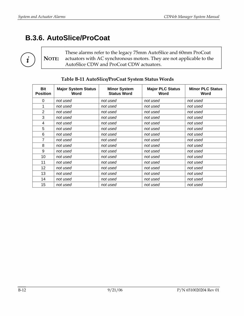
System and Actuator Alarms CDWeb Manager System Manual
B.3.6. AutoSlice/ProCoat
i
NOTE: These alarms refer to the legacy 75mm AutoSlice and 60mm ProCoat actuators with AC synchronous motors. They are not applicable to the AutoSlice CDW and ProCoat CDW actuators.
Table B-11 AutoSlice/ProCoat System Status Words
Bit Position
Major System Status Word
Minor System Status Word
Major PLC Status Word
Minor PLC Status Word
0 not used not used not used not used 1 not used not used not used not used 2 not used not used not used not used 3 not used not used not used not used 4 not used not used not used not used 5 not used not used not used not used 6 not used not used not used not used 7 not used not used not used not used 8 not used not used not used not used 9 not used not used not used not used 10 not used not used not used not used 11 not used not used not used not used 12 not used not used not used not used 13 not used not used not used not used 14 not used not used not used not used 15 not used not used not used not used
9/21/06 P/N 6510020204 Rev 01 B-12
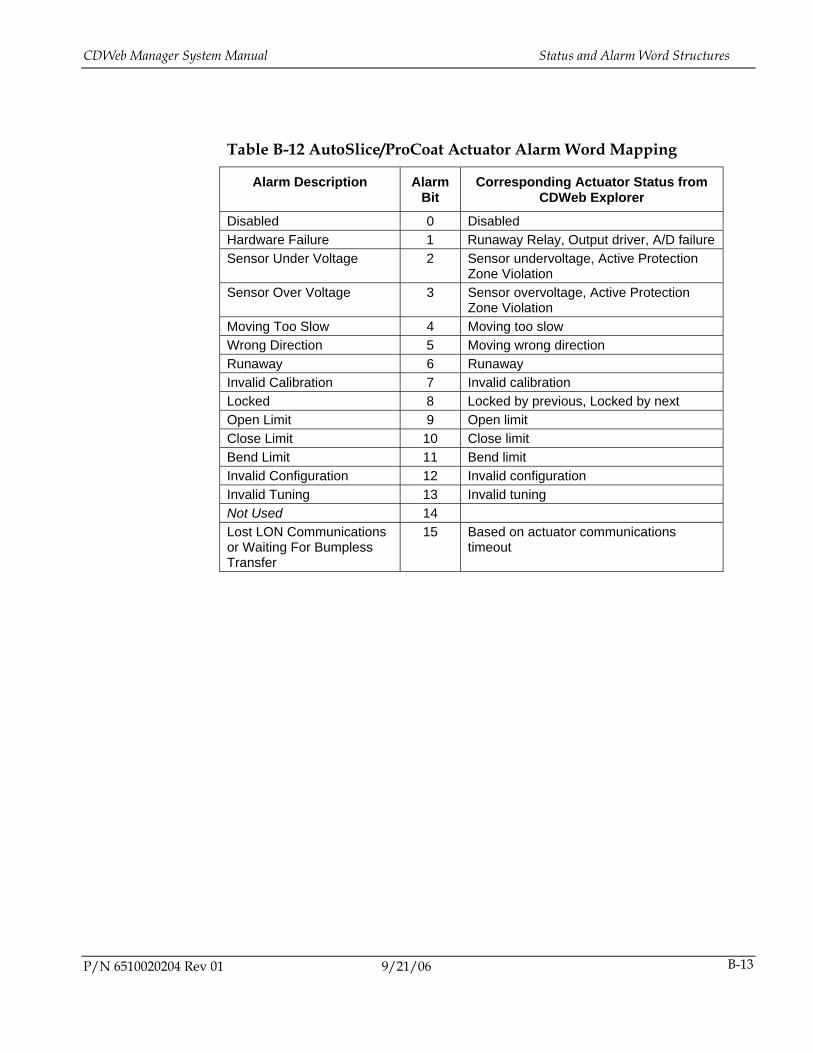
CDWeb Manager System Manual Status and Alarm Word Structures
P/N 6510020204 Rev 01 9/21/06 B-13
Table B-12 AutoSlice/ProCoat Actuator Alarm Word Mapping
Alarm Description Alarm Bit
Corresponding Actuator Status from CDWeb Explorer
Disabled 0 Disabled Hardware Failure 1 Runaway Relay, Output driver, A/D failure Sensor Under Voltage 2 Sensor undervoltage, Active Protection
Zone Violation Sensor Over Voltage 3 Sensor overvoltage, Active Protection
Zone Violation Moving Too Slow 4 Moving too slow Wrong Direction 5 Moving wrong direction Runaway 6 Runaway Invalid Calibration 7 Invalid calibration Locked 8 Locked by previous, Locked by next Open Limit 9 Open limit Close Limit 10 Close limit Bend Limit 11 Bend limit Invalid Configuration 12 Invalid configuration Invalid Tuning 13 Invalid tuning Not Used 14 Lost LON Communications or Waiting For Bumpless Transfer
15 Based on actuator communications timeout
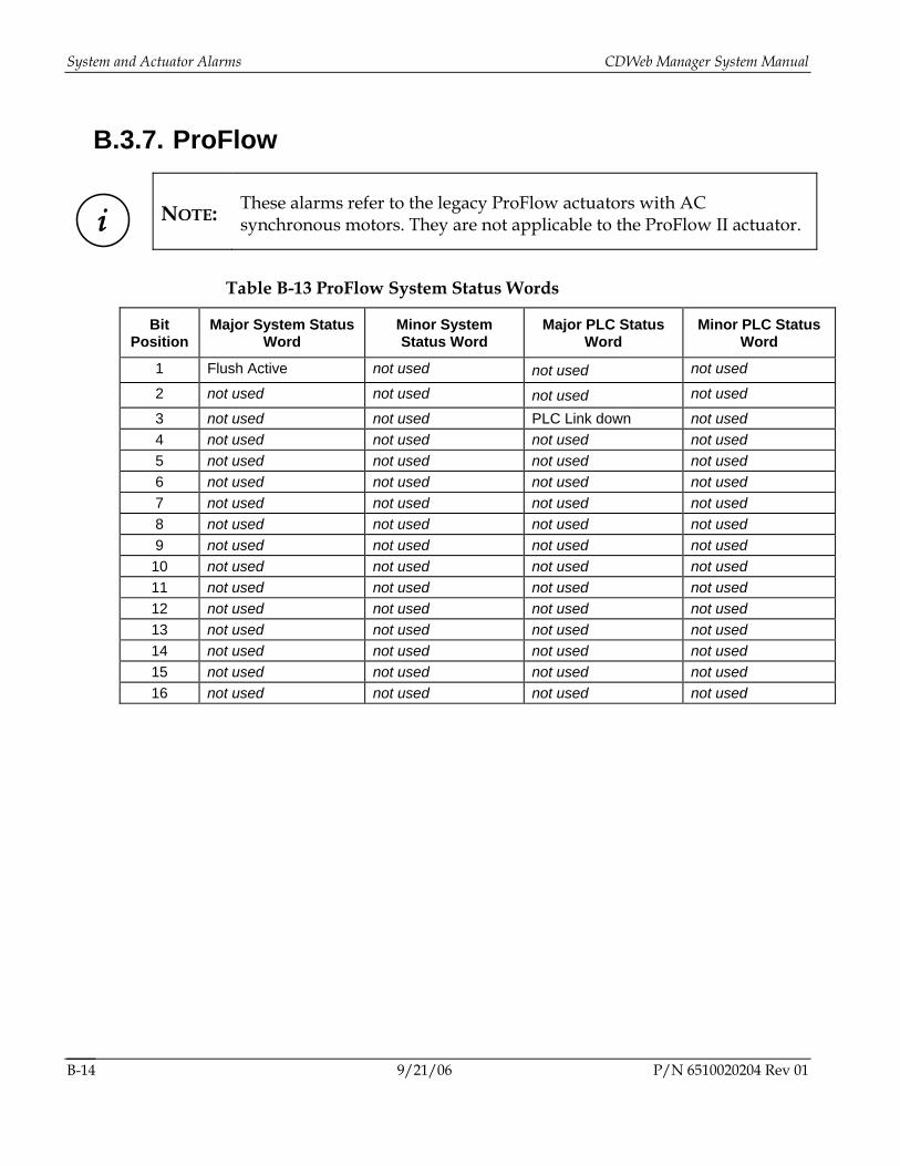
System and Actuator Alarms CDWeb Manager System Manual
B.3.7. ProFlow
i
NOTE: These alarms refer to the legacy ProFlow actuators with AC synchronous motors. They are not applicable to the ProFlow II actuator.
Table B-13 ProFlow System Status Words
Bit Position
Major System Status Word
Minor System Status Word
Major PLC Status Word
Minor PLC Status Word
1 Flush Active not used not used not used
2 not used not used not used not used
3 not used not used PLC Link down not used 4 not used not used not used not used 5 not used not used not used not used 6 not used not used not used not used 7 not used not used not used not used 8 not used not used not used not used 9 not used not used not used not used 10 not used not used not used not used 11 not used not used not used not used 12 not used not used not used not used 13 not used not used not used not used 14 not used not used not used not used 15 not used not used not used not used 16 not used not used not used not used
9/21/06 P/N 6510020204 Rev 01 B-14
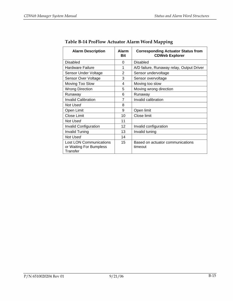
CDWeb Manager System Manual Status and Alarm Word Structures
P/N 6510020204 Rev 01 9/21/06 B-15
Table B-14 ProFlow Actuator Alarm Word Mapping
Alarm Description Alarm Bit
Corresponding Actuator Status from CDWeb Explorer
Disabled 0 Disabled Hardware Failure 1 A/D failure, Runaway relay, Output Driver Sensor Under Voltage 2 Sensor undervoltage Sensor Over Voltage 3 Sensor overvoltage Moving Too Slow 4 Moving too slow Wrong Direction 5 Moving wrong direction Runaway 6 Runaway Invalid Calibration 7 Invalid calibration Not Used 8 Open Limit 9 Open limit Close Limit 10 Close limit Not Used 11 Invalid Configuration 12 Invalid configuration Invalid Tuning 13 Invalid tuning Not Used 14 Lost LON Communications or Waiting For Bumpless Transfer
15 Based on actuator communications timeout

6510020204 Rev 01 C-1
C. Host Communications
C.1. ODX
C.1.1. CDWeb Manager Network Communication Specification
This specification assumes that the CDWeb Manager contains client software for ODX communication. The CDWeb Manager is responsible for initiating all network communications between itself and the Supervisory Control System. The content of all messages adheres to the ODX Functional Specification.
If a discrepancy exists between this document and the ODX Functional Specification, use this document.
C.1.1.1. Introduction
The ODX client initiates all communications between the CDWeb Manager and the ODX server running on the Supervisory Control System. The communications between the client and server consists of
• symbols, which contain numeric or character data,
• ordinals, which are boolean flags, and
• events, which may be scheduled thereby causing some action to happen on the Supervisory Control System.
Host Communications CDWeb Manager System Manual
9/21/06 P/N 6510020204 Rev 01 C-2
For the ODX server, read requests may be on demand, periodic, or triggered by an ordinal change on the Supervisory Control System. Write requests are always on demand and have the option of specifying an event to be scheduled on the Supervisory Control System after the write is complete.
Each read or write request may contain multiple symbols and any given symbol may be associated with multiple read or write requests. Before any read or write request is attempted, all necessary symbols and ordinals are looked-up through the ODX server to determine the data type and array size on the Supervisory Control System. The ODX server sends and expects a value for each element in an array, regardless of whether or not the full array is valid from an application point of view.
The CDWeb Manager ODX client has hard-coded read and write request templates that contain required symbol, ordinal, and event names. All symbol and ordinal names used for communication by a given CDWeb Manager are prefixed by a common 6 character actuator identifier. This actuator id has the form PxCyyy,
Where
x represents the process number
yyy represents the actuator type and gauge number, for example, WP1 for the first weight control actuator.
The remainder of the symbol name (for example, ASP) identifies the parameter type. Some small amount of information about the symbol can be extracted by examining the character(s) which separate the actuator and parameter identifiers. An underscore ( _ ) indicates an array and a period ( . ) indicates an ordinal. An ordinal array is therefore indicated by a period followed by an underscore ( ._ ).
In general, the CDWeb Manager does not use ordinal arrays. Instead, individual boolean flags are compacted into 16-bit status words that are transmitted to the Supervisory Control System as unsigned integers. It is the responsibility of the application software on the Supervisory Control System to break these unsigned integers out into the appropriate ordinal arrays for alarm and status reporting.
Event names are of the form LPNz\EVTnnn, where z represents the LPN number of the master Supervisory Control System, and nnn represents the event number. In general, all status changes for all possible LAN based
CDWeb Manager System Manual ODX
P/N 6510020204 Rev 01 9/21/06 C-3
CDWeb Managers are funneled through a single event, EVT586. For this reason, each write request made by the client that requires a status update on the Supervisory Control System also sets a corresponding control ordinal prior to scheduling the Status Change event. In this way the chain which runs off the Status Change event can decipher which data needs to be updated. All symbol, control ordinal, and event names required for a single ODX client are listed in Table C-1.
The ODX client logs into the Supervisory Control System with a user name of IDS and a password of RESULTS.
If the ODX client detects that communications have been lost, it resets itself to a startup condition. When communications are re-established, all data that is specified to be transferred on a startup condition is transferred.
Read Number of Actuator Zones
The ODX client reads the number of actuator zones from the Supervisory Control System (PxCyyyNUMACT) once on startup. This value is compared against the number of actuator zones in the CDWeb Manager configuration. If a discrepancy is found the client sets the corresponding bit in the LAN alarm word (see below) and attempts to write this word to the Supervisory Control System.
Write LAN Alarm Word
The ODX client writes the LAN alarm word PxCyyyLALM to the Supervisory Control System to identify possible problems with the LAN configuration. Currently there are only two bits defined in the status word:
• bit 0: a symbol lookup failure occurred
• bit 1: a mismatch was found in the number of configured zones
This word is written once after the symbol lookup and the comparison of actuator zones has been completed. This write either clears or sets the corresponding alarm states on the Supervisory Control System. As with all status words, the associated status change ordinal PxCyyy.LALM is set and the status change event LPNz\EVT586 is scheduled by this write request.
Host Communications CDWeb Manager System Manual
9/21/06 P/N 6510020204 Rev 01 C-4
Write System Status
The ODX client writes the four system status words PxCyyy_SST on a periodic basis. The four system status words are defined as: Major System Alarms, Minor System Alarms, Major PLC Alarms, and Minor PLC Alarms, and all correspond with older systems.
In some CDWeb systems an I/O subsystem is present for the management of interlocks or other digital inputs. When such a device is present but not communicating, the ODX client sets the PLC Not Ready For Control alarm (bit 2) in the Major PLC Alarm word. When the device is communicating, the I/O points are read directly from the device and mapped to the status words.
As with all status words, the associated status change ordinal PxCyyy.SST is set and the status change event LPNz\EVT586 is scheduled by this write request.
Read Set point and Position Scaling
The scaling information consists of the slope (slope (PxCyyyACTSLP) and offset (PxCyyyACTOFF). These values are used to convert between the position and set point scales used on the Supervisory Control System and the position and set point scales used by the actuators. These values are read whenever a connection is established with the Supervisory Control System.
A potential problem exists for any ODX client which reads these values. The Supervisory Control System stores these values in the ISR data. When the Supervisory Control System is starting up after a shutdown or reset, the ODX server is initialized before the ISR data is loaded. It is possible for a client to log in and read these values before they have been properly loaded. To remedy this potential situation, the CDWeb Manager not only reads these values when a connection is established, but continues to read them on a timed basis.
Read Actuator Set points
The ODX client reads actuator set point information on a periodic basis. The set point information consists of the actual set point array (PxCyyy_ASP). The time period between reads is hard-coded at 5 seconds.
CDWeb Manager System Manual ODX
P/N 6510020204 Rev 01 9/21/06 C-5
The set point array always contains floating point values. The slope and offset required to go from the Supervisory Control System to the actuator set point format is also read from the Supervisory Control System. The actuator task scales the set points appropriately before forwarding them to the actuators. The ODX client assumes that the actuators ignore set points when disabled.
Due to the asynchronous nature of the communication between the actuators and the CDWeb Manager and between the CDWeb Manager and the Supervisory Control System, set points can become corrupted when performing a bumpless transfer. When the Supervisory Control System performs a bumpless transfer, it copies its position array into its set point array. Similarly, on receiving a reset, an actuator copies its position into its control set point. However, there is no guarantee that the entry in the AM’s position array corresponds to the current actuator position because of the time lag in communication between the actuator and the Supervisory Control System. The CDWeb Manager guards against this situation by discarding set points for any actuator which has not reported its position within a time limit defined in the CDWeb Manager configuration. This situation is indicated by setting the Lost LON Communications bit in the actuator alarm word. Set points continue to be discarded until the position has been successfully reported to the Supervisory Control System and the Supervisory Control System has acknowledged the new position by sending a reset. This acknowledgment normally involves an operator invoking a Reset Failed Actuator or a Reset All Actuators command.
Write Actuator Positions and Status
The ODX client writes actuator positions, PxCyyy_APOS, and status, PxCyyy_ASTAT, to the Supervisory Control System on a periodic basis. As with all status words, the associated status change ordinal PxCyyy.ASTAT is set and the status change event LPNz\EVT586 is scheduled by each write request. The time period between transmissions is hard-coded at five seconds.
The position array always contains floating point values which are in the same units as the set point array. As with the set point array, the CDWeb Manager scales the positions appropriately before writing them to the Supervisory Control System. Positions are written to the Supervisory Control System regardless of the state of the Supervisory Control System Auto/Manual ordinal to facilitate bumpless transfer between modes.
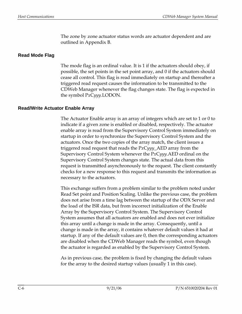
Host Communications CDWeb Manager System Manual
9/21/06 P/N 6510020204 Rev 01 C-6
The zone by zone actuator status words are actuator dependent and are outlined in Appendix B.
Read Mode Flag
The mode flag is an ordinal value. It is 1 if the actuators should obey, if possible, the set points in the set point array, and 0 if the actuators should cease all control. This flag is read immediately on startup and thereafter a triggered read request causes the information to be transmitted to the CDWeb Manager whenever the flag changes state. The flag is expected in the symbol PxCyyy.LODON.
Read/Write Actuator Enable Array
The Actuator Enable array is an array of integers which are set to 1 or 0 to indicate if a given zone is enabled or disabled, respectively. The actuator enable array is read from the Supervisory Control System immediately on startup in order to synchronize the Supervisory Control System and the actuators. Once the two copies of the array match, the client issues a triggered read request that reads the PxCyyy_AED array from the Supervisory Control System whenever the PxCyyy.AED ordinal on the Supervisory Control System changes state. The actual data from this request is transmitted asynchronously to the request. The client constantly checks for a new response to this request and transmits the information as necessary to the actuators.
This exchange suffers from a problem similar to the problem noted under Read Set point and Position Scaling. Unlike the previous case, the problem does not arise from a time lag between the startup of the ODX Server and the load of the ISR data, but from incorrect initialization of the Enable Array by the Supervisory Control System. The Supervisory Control System assumes that all actuators are enabled and does not ever initialize this array until a change is made in the array. Consequently, until a change is made in the array, it contains whatever default values it had at startup. If any of the default values are 0, then the corresponding actuators are disabled when the CDWeb Manager reads the symbol, even though the actuator is regarded as enabled by the Supervisory Control System.
As in previous case, the problem is fixed by changing the default values for the array to the desired startup values (usually 1 in this case).
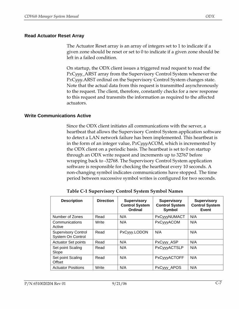
CDWeb Manager System Manual ODX
P/N 6510020204 Rev 01 9/21/06 C-7
Read Actuator Reset Array
The Actuator Reset array is an array of integers set to 1 to indicate if a given zone should be reset or set to 0 to indicate if a given zone should be left in a failed condition.
On startup, the ODX client issues a triggered read request to read the PxCyyy_ARST array from the Supervisory Control System whenever the PxCyyy.ARST ordinal on the Supervisory Control System changes state. Note that the actual data from this request is transmitted asynchronously to the request. The client, therefore, constantly checks for a new response to this request and transmits the information as required to the affected actuators.
Write Communications Active
Since the ODX client initiates all communications with the server, a heartbeat that allows the Supervisory Control System application software to detect a LAN network failure has been implemented. This heartbeat is in the form of an integer value, PxCyyyACOM, which is incremented by the ODX client on a periodic basis. The heartbeat is set to 0 on startup through an ODX write request and increments up to 32767 before wrapping back to -32768. The Supervisory Control System application software is responsible for checking the heartbeat every 10 seconds. A non-changing symbol indicates communications have stopped. The time period between successive symbol writes is configured for two seconds.
Table C-1 Supervisory Control System Symbol Names
Description Direction Supervisory Control System
Ordinal
Supervisory Control System
Symbol
Supervisory Control System
Event
Number of Zones Read N/A PxCyyyNUMACT N/A Communications Active
Write N/A PxCyyyACOM N/A
Supervisory Control System On Control
Read PxCyyy.LODON N/A N/A
Actuator Set points Read N/A PxCyyy_ASP N/A Set point Scaling Slope
Read N/A PxCyyyACTSLP N/A
Set point Scaling Offset
Read N/A PxCyyyACTOFF N/A
Actuator Positions Write N/A PxCyyy_APOS N/A
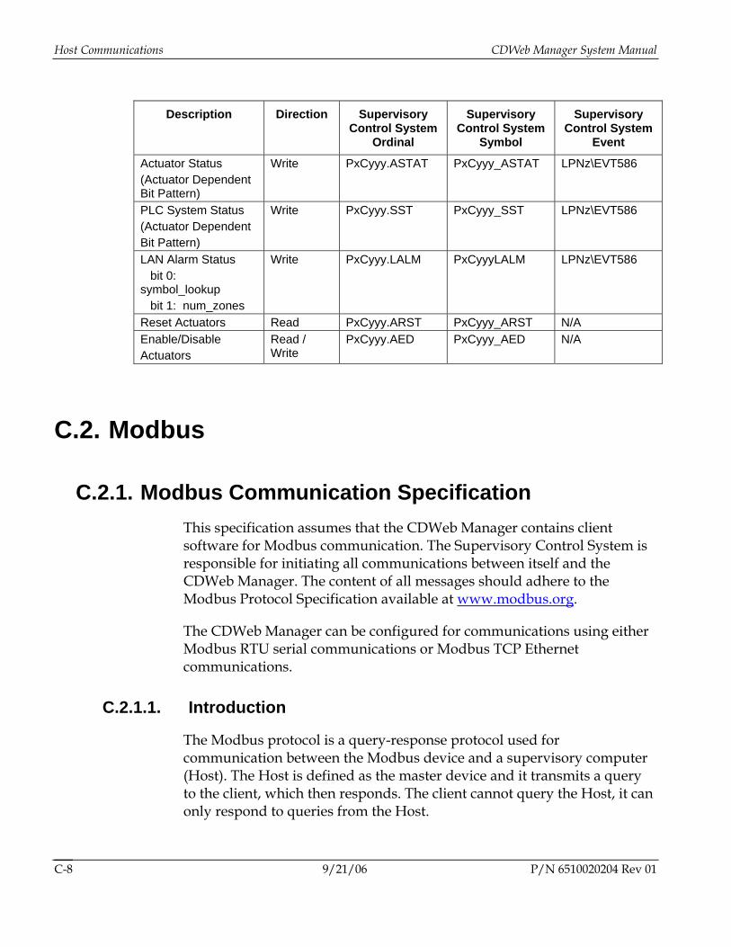
Host Communications CDWeb Manager System Manual
9/21/06 P/N 6510020204 Rev 01 C-8
Description Direction Supervisory Control System
Ordinal
Supervisory Control System
Symbol
Supervisory Control System
Event
Actuator Status (Actuator Dependent Bit Pattern)
Write PxCyyy.ASTAT PxCyyy_ASTAT LPNz\EVT586
PLC System Status (Actuator Dependent Bit Pattern)
Write PxCyyy.SST PxCyyy_SST LPNz\EVT586
LAN Alarm Status bit 0: symbol_lookup bit 1: num_zones
Write PxCyyy.LALM PxCyyyLALM LPNz\EVT586
Reset Actuators Read PxCyyy.ARST PxCyyy_ARST N/A Enable/Disable Actuators
Read / Write
PxCyyy.AED PxCyyy_AED N/A
C.2. Modbus
C.2.1. Modbus Communication Specification This specification assumes that the CDWeb Manager contains client software for Modbus communication. The Supervisory Control System is responsible for initiating all communications between itself and the CDWeb Manager. The content of all messages should adhere to the Modbus Protocol Specification available at www.modbus.org.
The CDWeb Manager can be configured for communications using either Modbus RTU serial communications or Modbus TCP Ethernet communications.
C.2.1.1. Introduction
The Modbus protocol is a query-response protocol used for communication between the Modbus device and a supervisory computer (Host). The Host is defined as the master device and it transmits a query to the client, which then responds. The client cannot query the Host, it can only respond to queries from the Host.
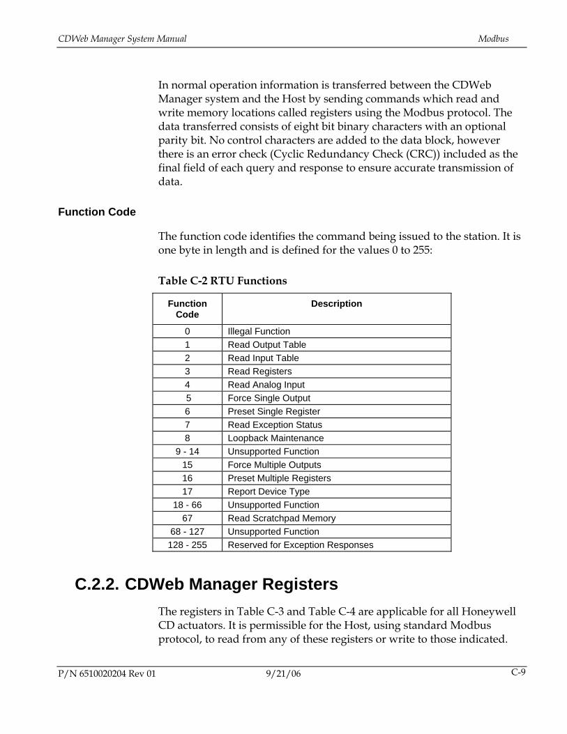
CDWeb Manager System Manual Modbus
P/N 6510020204 Rev 01 9/21/06 C-9
In normal operation information is transferred between the CDWeb Manager system and the Host by sending commands which read and write memory locations called registers using the Modbus protocol. The data transferred consists of eight bit binary characters with an optional parity bit. No control characters are added to the data block, however there is an error check (Cyclic Redundancy Check (CRC)) included as the final field of each query and response to ensure accurate transmission of data.
Function Code
The function code identifies the command being issued to the station. It is one byte in length and is defined for the values 0 to 255:
Table C-2 RTU Functions
Function Code
Description
0 Illegal Function 1 Read Output Table 2 Read Input Table 3 Read Registers 4 Read Analog Input 5 Force Single Output 6 Preset Single Register 7 Read Exception Status 8 Loopback Maintenance
9 - 14 Unsupported Function 15 Force Multiple Outputs 16 Preset Multiple Registers 17 Report Device Type
18 - 66 Unsupported Function 67 Read Scratchpad Memory
68 - 127 Unsupported Function 128 - 255 Reserved for Exception Responses
C.2.2. CDWeb Manager Registers The registers in Table C-3 and Table C-4 are applicable for all Honeywell CD actuators. It is permissible for the Host, using standard Modbus protocol, to read from any of these registers or write to those indicated.
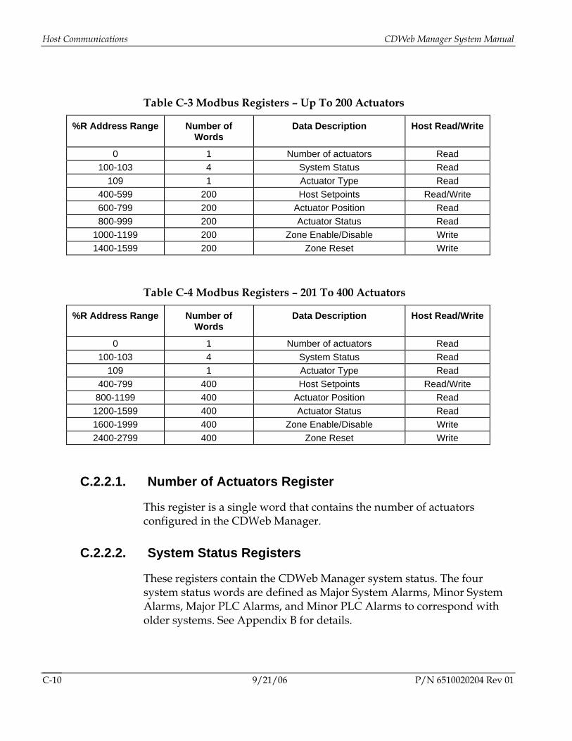
Host Communications CDWeb Manager System Manual
9/21/06 P/N 6510020204 Rev 01 C-10
Table C-3 Modbus Registers – Up To 200 Actuators
%R Address Range Number of Words
Data Description Host Read/Write
0 1 Number of actuators Read 100-103 4 System Status Read
109 1 Actuator Type Read 400-599 200 Host Setpoints Read/Write 600-799 200 Actuator Position Read 800-999 200 Actuator Status Read
1000-1199 200 Zone Enable/Disable Write 1400-1599 200 Zone Reset Write
Table C-4 Modbus Registers – 201 To 400 Actuators
%R Address Range Number of Words
Data Description Host Read/Write
0 1 Number of actuators Read 100-103 4 System Status Read
109 1 Actuator Type Read 400-799 400 Host Setpoints Read/Write
800-1199 400 Actuator Position Read 1200-1599 400 Actuator Status Read 1600-1999 400 Zone Enable/Disable Write 2400-2799 400 Zone Reset Write
C.2.2.1. Number of Actuators Register
This register is a single word that contains the number of actuators configured in the CDWeb Manager.
C.2.2.2. System Status Registers
These registers contain the CDWeb Manager system status. The four system status words are defined as Major System Alarms, Minor System Alarms, Major PLC Alarms, and Minor PLC Alarms to correspond with older systems. See Appendix B for details.
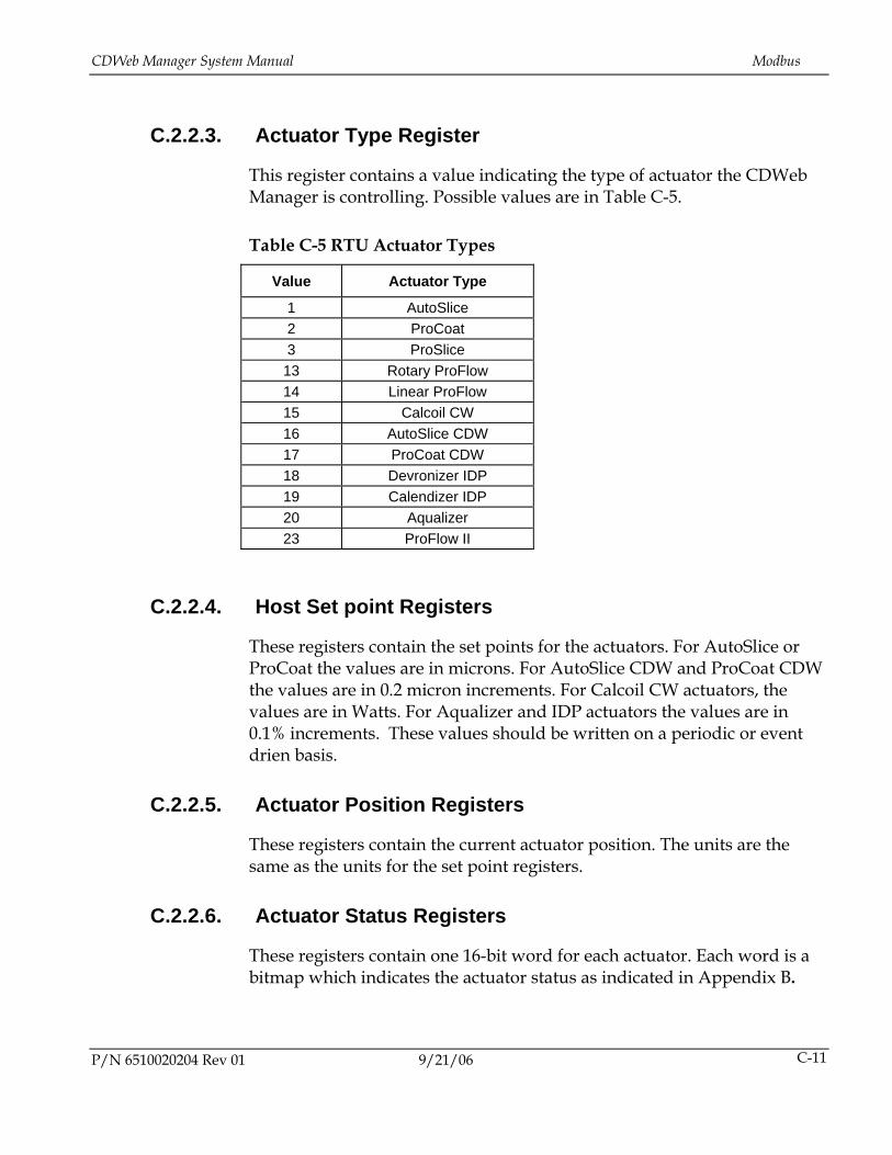
CDWeb Manager System Manual Modbus
P/N 6510020204 Rev 01 9/21/06 C-11
C.2.2.3. Actuator Type Register
This register contains a value indicating the type of actuator the CDWeb Manager is controlling. Possible values are in Table C-5.
Table C-5 RTU Actuator Types
Value Actuator Type
1 AutoSlice 2 ProCoat 3 ProSlice
13 Rotary ProFlow 14 Linear ProFlow 15 Calcoil CW 16 AutoSlice CDW 17 ProCoat CDW 18 Devronizer IDP 19 Calendizer IDP 20 Aqualizer 23 ProFlow II
C.2.2.4. Host Set point Registers
These registers contain the set points for the actuators. For AutoSlice or ProCoat the values are in microns. For AutoSlice CDW and ProCoat CDW the values are in 0.2 micron increments. For Calcoil CW actuators, the values are in Watts. For Aqualizer and IDP actuators the values are in 0.1% increments. These values should be written on a periodic or event drien basis.
C.2.2.5. Actuator Position Registers
These registers contain the current actuator position. The units are the same as the units for the set point registers.
C.2.2.6. Actuator Status Registers
These registers contain one 16-bit word for each actuator. Each word is a bitmap which indicates the actuator status as indicated in Appendix B.
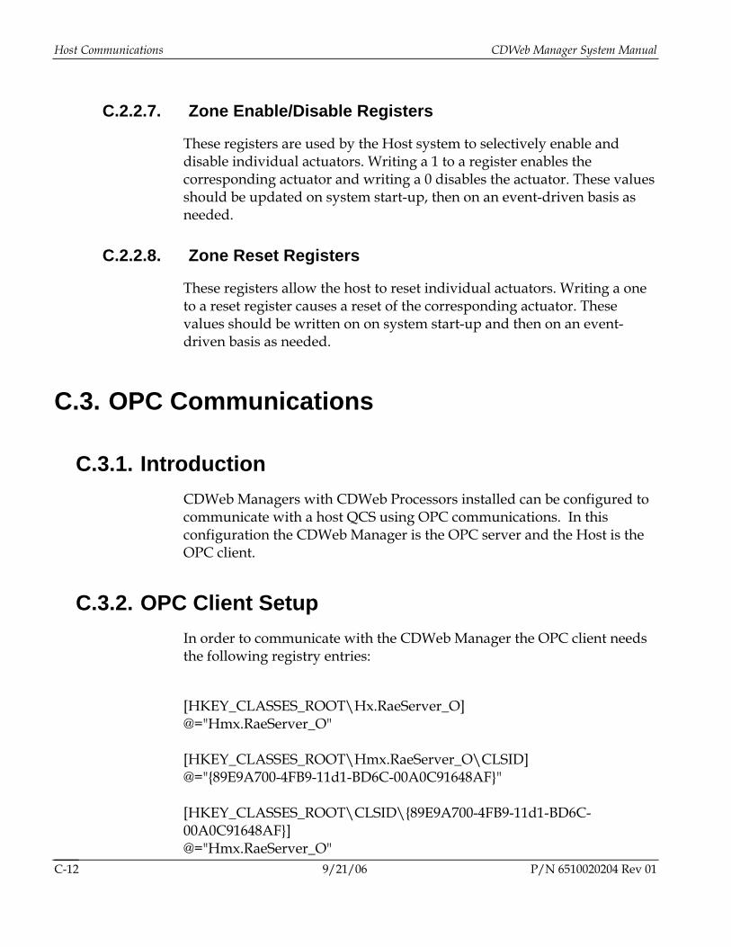
Host Communications CDWeb Manager System Manual
9/21/06 P/N 6510020204 Rev 01 C-12
C.2.2.7. Zone Enable/Disable Registers
These registers are used by the Host system to selectively enable and disable individual actuators. Writing a 1 to a register enables the corresponding actuator and writing a 0 disables the actuator. These values should be updated on system start-up, then on an event-driven basis as needed.
C.2.2.8. Zone Reset Registers
These registers allow the host to reset individual actuators. Writing a one to a reset register causes a reset of the corresponding actuator. These values should be written on on system start-up and then on an event-driven basis as needed.
C.3. OPC Communications
C.3.1. Introduction CDWeb Managers with CDWeb Processors installed can be configured to communicate with a host QCS using OPC communications. In this configuration the CDWeb Manager is the OPC server and the Host is the OPC client.
C.3.2. OPC Client Setup In order to communicate with the CDWeb Manager the OPC client needs the following registry entries:
[HKEY_CLASSES_ROOT\Hx.RaeServer_O] @="Hmx.RaeServer_O" [HKEY_CLASSES_ROOT\Hmx.RaeServer_O\CLSID] @="{89E9A700-4FB9-11d1-BD6C-00A0C91648AF}" [HKEY_CLASSES_ROOT\CLSID\{89E9A700-4FB9-11d1-BD6C-00A0C91648AF}] @="Hmx.RaeServer_O"

CDWeb Manager System Manual OPC Communications
P/N 6510020204 Rev 01 9/21/06 C-13
"AppID"="{89E9A700-4FB9-11d1-BD6C-00A0C91648AF}" [HKEY_CLASSES_ROOT\CLSID\{89E9A700-4FB9-11d1-BD6C-00A0C91648AF}\LocalServer32] @="%mxroot%\\rae\\bin\\OpcServer.exe" [HKEY_CLASSES_ROOT\CLSID\{89E9A700-4FB9-11d1-BD6C-00A0C91648AF}\ProgID] @="Hmx.RaeServer_O" [HKEY_CLASSES_ROOT\AppID\{89E9A700-4FB9-11d1-BD6C-00A0C91648AF}] @="HMX RAE OPC COMPONENT - exe Server" [HKEY_LOCAL_MACHINE\SOFTWARE\Classes\Hmx.RaeServer_O\OPC] @="" [HKEY_LOCAL_MACHINE\SOFTWARE\Classes\Hmx.RaeServer_O\OPC\Vendor] @="Honeywell IAC Inc."
C.3.3. OPC Tagnames The following tags are used for CDWeb Manager Control:
Table C-6 OPC Tagnames
Tag Name Data format
Data Type
Read/Write Description/Usage
act.setpoint array double Write/Read Actuator setpoints: Update periodically, or when new setpoints are available.
act.position array double Read Actuator positions: Read periodically (positions are updated every 10 seconds).
act.enable array word Write/read Actuator Enable: 1 indicates enabled, 0 indicates disabled. Host must enable actuators on startup, then event driven.
act.reset array word Write/read Actuator Reset: 1 indicates that the actuator is to be reset. This value is set to clear any actuator alarms.
Act.sys.status Array [4] word Read System Status: see actuator specific system status word definition (Appendix B)
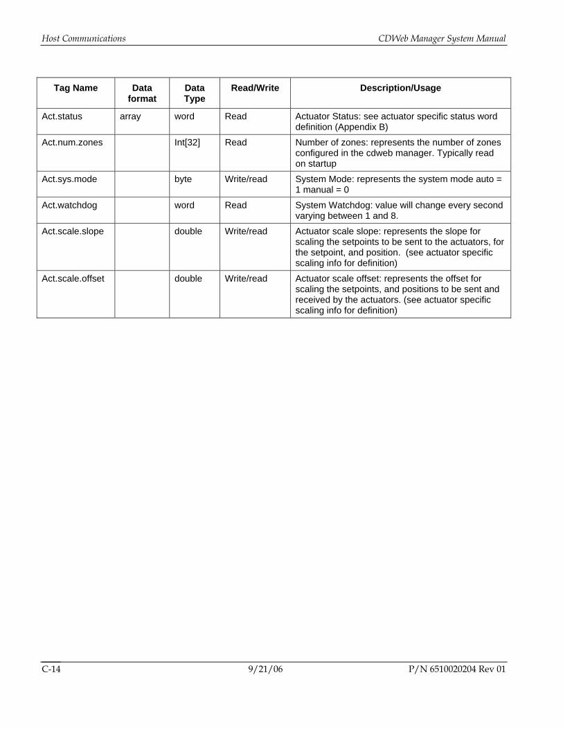
Host Communications CDWeb Manager System Manual
9/21/06 P/N 6510020204 Rev 01 C-14
Tag Name Data format
Data Type
Read/Write Description/Usage
Act.status array word Read Actuator Status: see actuator specific status word definition (Appendix B)
Act.num.zones Int[32] Read Number of zones: represents the number of zones configured in the cdweb manager. Typically read on startup
Act.sys.mode byte Write/read System Mode: represents the system mode auto = 1 manual = 0
Act.watchdog word Read System Watchdog: value will change every second varying between 1 and 8.
Act.scale.slope double Write/read Actuator scale slope: represents the slope for scaling the setpoints to be sent to the actuators, for the setpoint, and position. (see actuator specific scaling info for definition)
Act.scale.offset double Write/read Actuator scale offset: represents the offset for scaling the setpoints, and positions to be sent and received by the actuators. (see actuator specific scaling info for definition)