10 analytical and medical x-rays - university of … of high energy electrons produced electrically...
TRANSCRIPT
10 Analytical and Medical X-rays
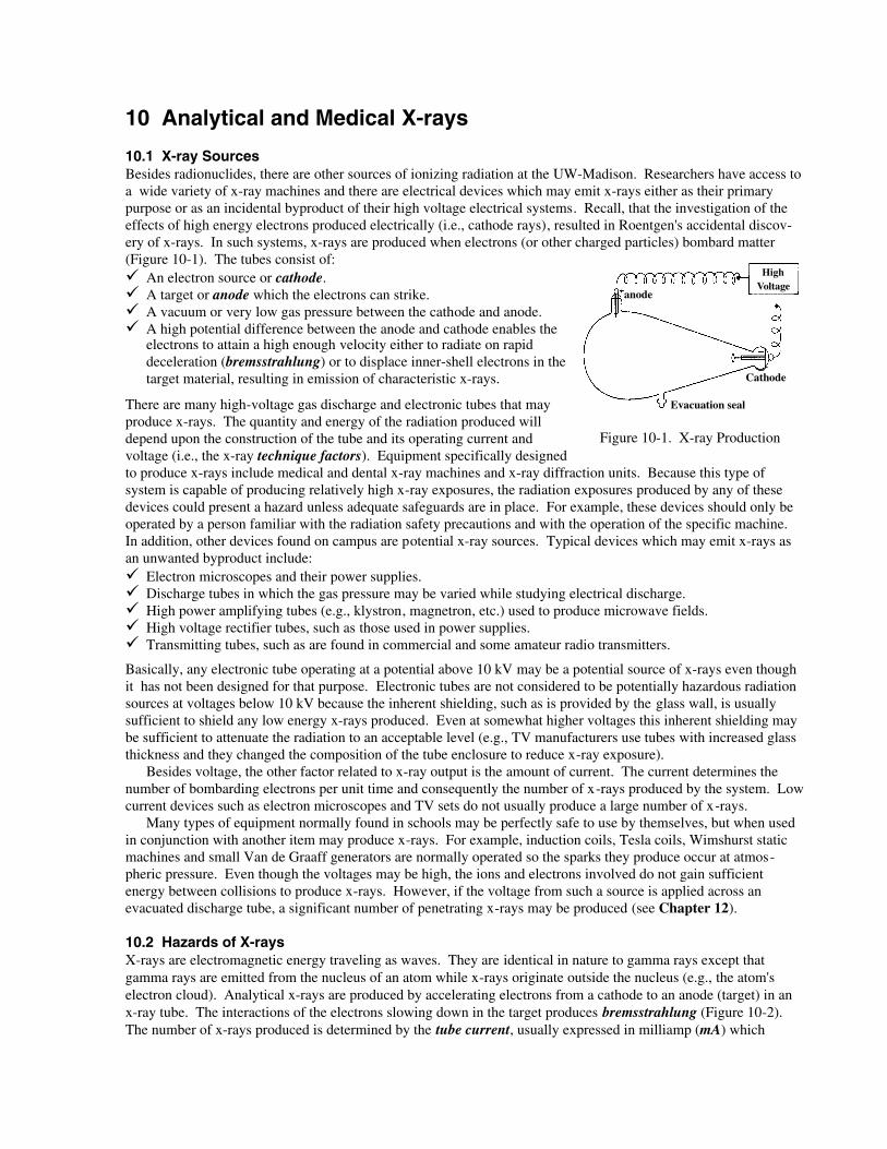
10.1 X-ray SourcesBesides radionuclides, there are other sources of ionizing radiation at the UW-Madison. Researchers have access toa wide variety of x-ray machines and there are electrical devices which may emit x-rays either as their primarypurpose or as an incidental byproduct of their high voltage electrical systems. Recall, that the investigation of theeffects of high energy electrons produced electrically (i.e., cathode rays), resulted in Roentgen's accidental discov-ery of x-rays. In such systems, x-rays are produced when electrons (or other charged particles) bombard matter(Figure 10-1). The tubes consist of:
An electron source or cathode.A target or anode which the electrons can strike.A vacuum or very low gas pressure between the cathode and anode.A high potential difference between the anode and cathode enables theelectrons to attain a high enough velocity either to radiate on rapiddeceleration (bremsstrahlung) or to displace inner-shell electrons in thetarget material, resulting in emission of characteristic x-rays.
There are many high-voltage gas discharge and electronic tubes that mayproduce x-rays. The quantity and energy of the radiation produced willdepend upon the construction of the tube and its operating current andvoltage (i.e., the x-ray technique factors). Equipment specifically designedto produce x-rays include medical and dental x-ray machines and x-ray diffraction units. Because this type ofsystem is capable of producing relatively high x-ray exposures, the radiation exposures produced by any of thesedevices could present a hazard unless adequate safeguards are in place. For example, these devices should only beoperated by a person familiar with the radiation safety precautions and with the operation of the specific machine.In addition, other devices found on campus are potential x-ray sources. Typical devices which may emit x-rays asan unwanted byproduct include:
Electron microscopes and their power supplies.Discharge tubes in which the gas pressure may be varied while studying electrical discharge.High power amplifying tubes (e.g., klystron, magnetron, etc.) used to produce microwave fields.High voltage rectifier tubes, such as those used in power supplies.Transmitting tubes, such as are found in commercial and some amateur radio transmitters.
Basically, any electronic tube operating at a potential above 10 kV may be a potential source of x-rays even thoughit has not been designed for that purpose. Electronic tubes are not considered to be potentially hazardous radiationsources at voltages below 10 kV because the inherent shielding, such as is provided by the glass wall, is usuallysufficient to shield any low energy x-rays produced. Even at somewhat higher voltages this inherent shielding maybe sufficient to attenuate the radiation to an acceptable level (e.g., TV manufacturers use tubes with increased glassthickness and they changed the composition of the tube enclosure to reduce x-ray exposure).
Besides voltage, the other factor related to x-ray output is the amount of current. The current determines thenumber of bombarding electrons per unit time and consequently the number of x-rays produced by the system. Lowcurrent devices such as electron microscopes and TV sets do not usually produce a large number of x-rays.
Many types of equipment normally found in schools may be perfectly safe to use by themselves, but when usedin conjunction with another item may produce x-rays. For example, induction coils, Tesla coils, Wimshurst staticmachines and small Van de Graaff generators are normally operated so the sparks they produce occur at atmos-pheric pressure. Even though the voltages may be high, the ions and electrons involved do not gain sufficientenergy between collisions to produce x-rays. However, if the voltage from such a source is applied across anevacuated discharge tube, a significant number of penetrating x-rays may be produced (see Chapter 12).
10.2 Hazards of X-raysX-rays are electromagnetic energy traveling as waves. They are identical in nature to gamma rays except thatgamma rays are emitted from the nucleus of an atom while x-rays originate outside the nucleus (e.g., the atom'selectron cloud). Analytical x-rays are produced by accelerating electrons from a cathode to an anode (target) in anx-ray tube. The interactions of the electrons slowing down in the target produces bremsstrahlung (Figure 10-2).The number of x-rays produced is determined by the tube current, usually expressed in milliamp (mA) which
Figure 10-1. X-ray Production
High Voltage
Evacuation seal
Cathode
anode
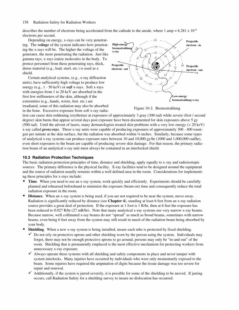
describes the number of electrons being accelerated from the cathode to the anode, where 1 amp = 6.281 x 10¹⁸
electrons per second. Depending on energy, x-rays can be very penetrat-
ing. The voltage of the system indicates how penetrat-ing the x-rays will be. The higher the voltage of thegenerator, the more penetrating the radiation. Just likegamma rays, x-rays ionize molecules in the body. Toprotect personnel from these penetrating rays, thick,dense material (e.g., lead, steel, etc.) is used as ashield.
Certain analytical systems, (e.g., x-ray diffractionunits), have sufficiently high voltage to produce lowenergy (e.g., 1 - 50 keV) or soft x-rays. Soft x-rayswith energies from 1 to 20 keV are absorbed in thefirst few millimeters of the skin, although if theextremities (e.g., hands, wrists, feet. etc.) areirradiated, some of this radiation may also be absorbedin the bone. Excessive exposure from soft x-ray radia-tion can cause skin reddening (erythema) at exposures of approximately 3 gray (300 rad) while severe (first / seconddegree) skin burns that appear several days post exposure have been documented for skin exposures above 5 gy(500 rad). Until the advent of lasers, many dermatologists treated skin problems with a very low energy (< 20 keV)x-ray called grenz-rays. These x-ray units were capable of producing exposures of approximately 300 - 400 roent -gen per minute at the skin surface, but the radiation was absorbed within ¼ inches. Similarly, because some typesof analytical x-ray systems can produce exposure rates between 10 and 10,000 gy/hr (1000 and 1,000,000 rad/hr),even short exposures to the beam are capable of producing severe skin damage. For that reason, the primary radia-tion beam of an analytical x-ray unit must always be contained in an interlocked shield.
10.3 Radiation Protection TechniquesThe basic radiation protection principles of time, distance and shielding, apply equally to x-ray and radioisotopicsources. The primary difference is the physical facility. X-ray facilities tend to be designed around the equipmentand the source of radiation usually remains within a well defined area in the room. Considerations for implementi-ng these principles for x-rays include:
Time. When you need to use an x-ray system, work quickly and efficiently. Experiments should be carefullyplanned and rehearsed beforehand to minimize the exposure (beam-on) time and consequently reduce the totalradiation exposure in the room.Distance. When an x-ray system is being used, if you are not required to be near the system, move away.Radiation is significantly reduced by distance (see Chapter 4), standing at least 6 feet from an x-ray radiationsource provides a great deal of protection. If the exposure at 1 foot is 1 R/hr, then at 6 feet the exposure hasbeen reduced to 0.027 R/hr (27 mR/hr). Note that many analytical x-ray systems use very narrow x-ray beams.Because narrow, well collimated x-ray beams do not “spread” as much as broad beams, sometimes with narrowbeams, even being 6 feet away from the system may still result in much of the radiation beam being absorbed byyour body.Shielding. When a new x-ray system is being installed, insure each tube is protected by fixed shielding.
Do not rely on protective aprons and other shielding worn by the person using the system. Individuals mayforget, there may not be enough protective aprons to go around, persons may only be “in-and-out” of theroom. Shielding that is permanently emplaced is the most effective mechanism for protecting workers fromunnecessary x-ray exposure.Always operate these systems with all shielding and safety components in place and never tamper withsystem interlocks. Many injuries have occurred by individuals who were only momentarily exposed to thebeam. Some injuries have required the amputation of digits because the tissue damage was too severe forrepair and renewal.Additionally, if the system is jarred severely, it is possible for some of the shielding to be moved. If jarringoccurs, call Radiation Safety for a shielding survey to insure no dislocation has occurred.
158 Radiation Safety for Radiation Workers
Figure 10-2. Bremsstrahlung
Low-energybremsstrahlung x-ray
Projectile electron - in
Projectile electron - out
Projectile electron - out
High-energybremsstrahlung x-ray
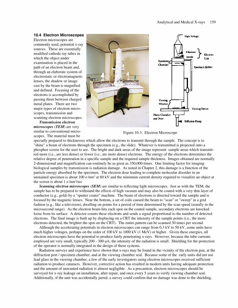
10.4 Electron MicroscopesElectron microscopes arecommonly used, potential x-raysources. These are essentiallymodified cathode ray tubes inwhich the object underexamination is placed in thepath of an electron beam and,through an elaborate system ofelectrostatic or electromagneticlenses, the shadow or imagecast by the beam is magnifiedand defined. Focusing of theelectrons is accomplished bypassing them between chargedmetal plates. There are twomajor types of electron micro-scopes, transmission andscanning electron microscopes.
Transmission electronmicroscopes (TEM) are verysimilar to conventional micro-scopes. The material must bespecially prepared to thicknesses which allow the electrons to transmit through the sample. The concept is to"shine" a beam of electrons through the specimen (e.g., the slide). Whatever is transmitted is projected onto aphosphor screen for the user to see. The bright and dark areas of the image represent sample areas which transmit-ted more (i.e., are less dense) or fewer (i.e., are more dense) electrons. The energy of the electrons determines therelative degree of penetration in a specific sample and the required sample thickness. Images obtained are normally2-dimensional and magnification can routinely be as great as 350,000-times. One limiting factor for imagingbiological samples by transmission is radiation damage. As noted in Chapter 2, this damage is a function of theparticle energy absorbed by the specimen. The electron dose leading to complete molecular disorder in anunstained specimen is about 100 e-/nm2 at 80 kV and the minimum current density required to visualize an object atthe screen is about 1 e-/nm2/sec
Scanning electron microscopes (SEM) are similar to reflecting light microscopes. Just as with the TEM, thesample has to be prepared to withstand the effects of high vacuum and may also be coated with a very thin layer ofconductor (e.g., gold) by a "sputter coater" machine. The beam of electrons is directed toward the sample and isfocused by the magnetic lenses. Near the bottom, a set of coils caused the beam to "scan" or "sweep" in a gridfashion (e.g., like a television), dwelling on points for a period of time determined by the scan speed (usually in themicrosecond range). As the electron beam hits each spot on the coated sample, secondary electrons are knockedloose from its surface. A detector counts these electrons and sends a signal proportional to the number of detectedelectrons. The final image is built up by displaying on a CRT the intensity of the sample points (i.e., the moreelectrons detected, the brighter the spot on the CRT). The entire pattern can be scanned 30 times per second.
Although the accelerating potentials in electron microscopes can range from 0.3 kV to 50 kV, some units havemuch higher voltages, perhaps on the order of 100 kV to 1000 kV (1 MeV) or higher. Given these energies, allelectron microscopes have the potential to produce fairly penetrating x-rays. However, because the tube currentsemployed are very small, typically 200 - 300 µA, the intensity of the radiation is small. Shielding for the protectionof the operator is normally integrated in the design of these systems.
Radiation surveys and experience have shown that x-rays may be found in the vicinity of the electron gun, at thediffraction port / specimen chamber, and at the viewing chamber seal. Because some of the early units did not uselead glass in the viewing chamber, a few of the early investigators using electron microscopes received sufficientradiation to produce cataracts. However, corrective action has resulted in modern units having adequate protectionand the amount of unwanted radiation is almost negligible. As a precaution, electron microscopes should besurveyed for x-ray leakage on installation, after repair, and once every 5 years to verify viewing chamber seal.Additionally, if the unit was accidentally jarred, a survey could confirm that no damage was done to the shielding.
Analytical and Medical X-rays 159
Figure 10-3. Electron Microscope
10.5 Analytical X-ray SystemsAnalytical x-ray machines (e.g., x-ray diffraction, x-ray crystallography, x-ray fluorescence, etc.) are used exten-sively for microstructure analysis in various research and teaching activities. When a sample is irradiated with aparallel beam of monochromatic x-rays, the atomic lattice of the sample acts as a 3-dimensional diffraction grating,causing the x-ray beam to be diffracted to specific angles related to the inter-atomic spacings. This x-ray pattern isrecorded by film or angular x-ray detectors. By measuring the angles of diffraction, the inter-atomic spacings of thematerial can be determined and used to identify the crystallographic structures of the material.
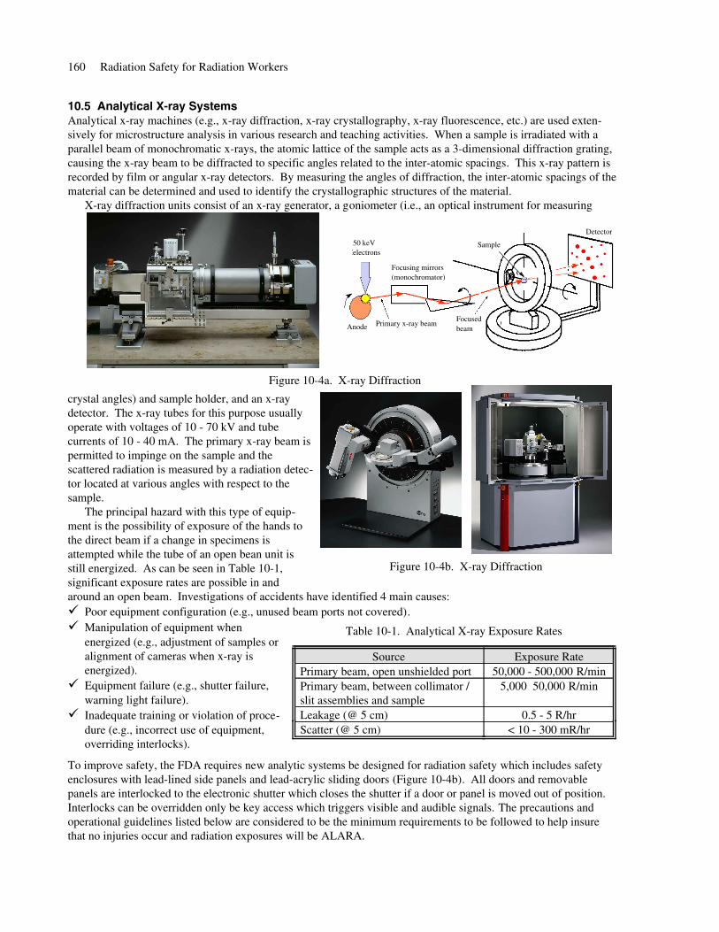
X-ray diffraction units consist of an x-ray generator, a goniometer (i.e., an optical instrument for measuring
crystal angles) and sample holder, and an x-raydetector. The x-ray tubes for this purpose usuallyoperate with voltages of 10 - 70 kV and tubecurrents of 10 - 40 mA. The primary x-ray beam ispermitted to impinge on the sample and thescattered radiation is measured by a radiation detec-tor located at various angles with respect to thesample.
The principal hazard with this type of equip-ment is the possibility of exposure of the hands tothe direct beam if a change in specimens isattempted while the tube of an open bean unit isstill energized. As can be seen in Table 10-1,significant exposure rates are possible in andaround an open beam. Investigations of accidents have identified 4 main causes:
Poor equipment configuration (e.g., unused beam ports not covered). Manipulation of equipment whenenergized (e.g., adjustment of samples oralignment of cameras when x-ray isenergized).Equipment failure (e.g., shutter failure,warning light failure).Inadequate training or violation of proce-dure (e.g., incorrect use of equipment,overriding interlocks).
To improve safety, the FDA requires new analytic systems be designed for radiation safety which includes safetyenclosures with lead-lined side panels and lead-acrylic sliding doors (Figure 10-4b). All doors and removablepanels are interlocked to the electronic shutter which closes the shutter if a door or panel is moved out of position.Interlocks can be overridden only be key access which triggers visible and audible signals. The precautions andoperational guidelines listed below are considered to be the minimum requirements to be followed to help insurethat no injuries occur and radiation exposures will be ALARA.
160 Radiation Safety for Radiation Workers
Figure 10-4a. X-ray Diffraction
50 keV electrons
Anode Primary x-ray beam
Focusing mirrors(monochromator)
Focusedbeam
Detector
Sample
Figure 10-4b. X-ray Diffraction
< 10 - 300 mR/hrScatter (@ 5 cm)0.5 - 5 R/hrLeakage (@ 5 cm)
5,000 50,000 R/minPrimary beam, between collimator /slit assemblies and sample
50,000 - 500,000 R/minPrimary beam, open unshielded portExposure RateSource
Table 10-1. Analytical X-ray Exposure Rates
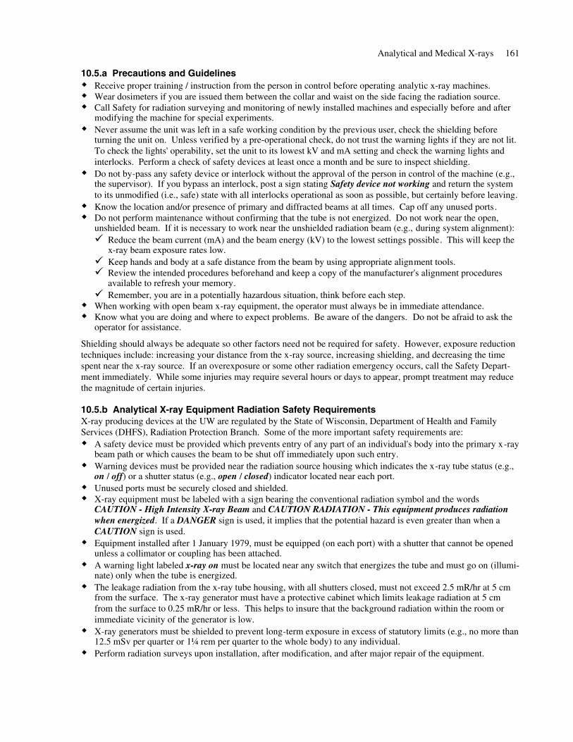
10.5.a Precautions and GuidelinesReceive proper training / instruction from the person in control before operating analytic x-ray machines.Wear dosimeters if you are issued them between the collar and waist on the side facing the radiation source.Call Safety for radiation surveying and monitoring of newly installed machines and especially before and aftermodifying the machine for special experiments.Never assume the unit was left in a safe working condition by the previous user, check the shielding beforeturning the unit on. Unless verified by a pre-operational check, do not trust the warning lights if they are not lit.To check the lights' operability, set the unit to its lowest kV and mA setting and check the warning lights andinterlocks. Perform a check of safety devices at least once a month and be sure to inspect shielding.Do not by-pass any safety device or interlock without the approval of the person in control of the machine (e.g.,the supervisor). If you bypass an interlock, post a sign stating Safety device not working and return the systemto its unmodified (i.e., safe) state with all interlocks operational as soon as possible, but certainly before leaving.Know the location and/or presence of primary and diffracted beams at all times. Cap off any unused ports.Do not perform maintenance without confirming that the tube is not energized. Do not work near the open,unshielded beam. If it is necessary to work near the unshielded radiation beam (e.g., during system alignment):
Reduce the beam current (mA) and the beam energy (kV) to the lowest settings possible. This will keep thex-ray beam exposure rates low. Keep hands and body at a safe distance from the beam by using appropriate alignment tools.Review the intended procedures beforehand and keep a copy of the manufacturer's alignment proceduresavailable to refresh your memory.Remember, you are in a potentially hazardous situation, think before each step.
When working with open beam x-ray equipment, the operator must always be in immediate attendance.Know what you are doing and where to expect problems. Be aware of the dangers. Do not be afraid to ask theoperator for assistance.
Shielding should always be adequate so other factors need not be required for safety. However, exposure reductiontechniques include: increasing your distance from the x-ray source, increasing shielding, and decreasing the timespent near the x-ray source. If an overexposure or some other radiation emergency occurs, call the Safety Depart-ment immediately. While some injuries may require several hours or days to appear, prompt treatment may reducethe magnitude of certain injuries.
10.5.b Analytical X-ray Equipment Radiation Safety RequirementsX-ray producing devices at the UW are regulated by the State of Wisconsin, Department of Health and FamilyServices (DHFS), Radiation Protection Branch. Some of the more important safety requirements are:
A safety device must be provided which prevents entry of any part of an individual's body into the primary x-raybeam path or which causes the beam to be shut off immediately upon such entry.Warning devices must be provided near the radiation source housing which indicates the x-ray tube status (e.g.,on / off) or a shutter status (e.g., open / closed) indicator located near each port.Unused ports must be securely closed and shielded.X-ray equipment must be labeled with a sign bearing the conventional radiation symbol and the wordsCAUTION - High Intensity X-ray Beam and CAUTION RADIATION - This equipment produces radiationwhen energized. If a DANGER sign is used, it implies that the potential hazard is even greater than when aCAUTION sign is used.Equipment installed after 1 January 1979, must be equipped (on each port) with a shutter that cannot be openedunless a collimator or coupling has been attached.A warning light labeled x-ray on must be located near any switch that energizes the tube and must go on (illumi-nate) only when the tube is energized.The leakage radiation from the x-ray tube housing, with all shutters closed, must not exceed 2.5 mR/hr at 5 cmfrom the surface. The x-ray generator must have a protective cabinet which limits leakage radiation at 5 cmfrom the surface to 0.25 mR/hr or less. This helps to insure that the background radiation within the room orimmediate vicinity of the generator is low.X-ray generators must be shielded to prevent long-term exposure in excess of statutory limits (e.g., no more than12.5 mSv per quarter or 1¼ rem per quarter to the whole body) to any individual.Perform radiation surveys upon installation, after modification, and after major repair of the equipment.
Analytical and Medical X-rays 161
Each room containing analytical x-ray equipment shall be posted with a sign bearing the radiation symbol andthe words CAUTION - X-ray equipment. Some variance may be allowed for medical x-ray equipment rooms.Only trained individuals are allowed to operate analytical x-ray equipment and written operating proceduresmust be available (i.e., in the room) to all persons who use the device.No safety devices may be bypassed without the approval of the person in control of the installation. If a safetydevice is bypassed, a conspicuous sign stating Safety device not working must be posted.No one may be permitted to operate an x-ray machine without receiving instruction on the radiation hazardsinvolved, safety devices, operating procedures, symptoms of acute localized exposure and procedures for report-ing a suspected overexposure.Records of safety surveys, routine calibrations and maintenance, and any modification from the originallyinstalled schematics must be maintained for the life of the equipment including the name of the person perform-ing this service.
10.6 Diagnostic X-raysAs noted in Chapter 3, the largest average exposure to the population of the U.S. after natural background resultsfrom diagnostic x-ray exposures (i.e., 0.53 mSv/yr -- 53 mrem/yr). While technology has introduced many newdiagnostic modalities (e.g., ultrasound, magnetic resonance, etc.) which do not use ionizing radiation, the use ofx-ray machines has continually expanded. Clinics likely to possess diagnostic x-ray units include: radiology,urology, cardiology, orthopedics, gastroenterology, neurology. These systems are used to check on injuries, detectcertain growths (mammography) or stones, assist in the placement of catheters, measure bone density, etc. In thissection we will review the production and use of diagnostic x-rays and protective measures.
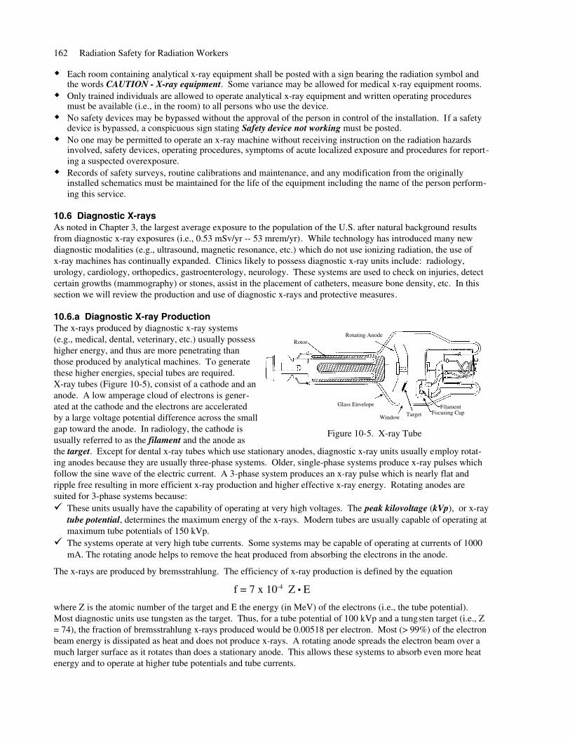
10.6.a Diagnostic X-ray ProductionThe x-rays produced by diagnostic x-ray systems(e.g., medical, dental, veterinary, etc.) usually possesshigher energy, and thus are more penetrating thanthose produced by analytical machines. To generatethese higher energies, special tubes are required.X-ray tubes (Figure 10-5), consist of a cathode and ananode. A low amperage cloud of electrons is gener-ated at the cathode and the electrons are acceleratedby a large voltage potential difference across the smallgap toward the anode. In radiology, the cathode isusually referred to as the filament and the anode asthe target. Except for dental x-ray tubes which use stationary anodes, diagnostic x-ray units usually employ rotat-ing anodes because they are usually three-phase systems. Older, single-phase systems produce x-ray pulses whichfollow the sine wave of the electric current. A 3-phase system produces an x-ray pulse which is nearly flat andripple free resulting in more efficient x-ray production and higher effective x-ray energy. Rotating anodes aresuited for 3-phase systems because:
These units usually have the capability of operating at very high voltages. The peak kilovoltage (kVp), or x-raytube potential, determines the maximum energy of the x-rays. Modern tubes are usually capable of operating atmaximum tube potentials of 150 kVp.The systems operate at very high tube currents. Some systems may be capable of operating at currents of 1000mA. The rotating anode helps to remove the heat produced from absorbing the electrons in the anode.
The x-rays are produced by bremsstrahlung. The efficiency of x-ray production is defined by the equation
f = 7 x 10⁻⁴ Z ● E
where Z is the atomic number of the target and E the energy (in MeV) of the electrons (i.e., the tube potential).Most diagnostic units use tungsten as the target. Thus, for a tube potential of 100 kVp and a tungsten target (i.e., Z= 74), the fraction of bremsstrahlung x-rays produced would be 0.00518 per electron. Most (> 99%) of the electronbeam energy is dissipated as heat and does not produce x-rays. A rotating anode spreads the electron beam over amuch larger surface as it rotates than does a stationary anode. This allows these systems to absorb even more heatenergy and to operate at higher tube potentials and tube currents.
162 Radiation Safety for Radiation Workers
Figure 10-5. X-ray Tube
RotorRotating Anode
Glass Envelope
Window TargetFilament
Focusing Cup
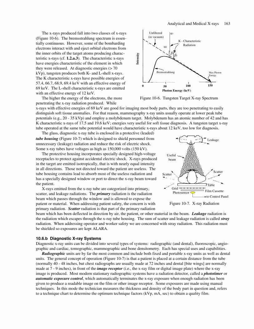
The x-rays produced fall into two classes of x-rays(Figure 10-6). The bremsstrahlung spectrum is essen-tially continuous. However, some of the bombardingelectrons interact with and eject orbital electrons fromthe inner orbits of the target atoms producing charac-teristic x-rays (cf. 1.2.a.3). The characteristic x-rayshave energies characteristic of the element in whichthey were released. At diagnostic energies (> 70kVp), tungsten produces both K- and L-shell x-rays.The K characteristic x-rays have possible energies of57.4, 66.7, 68.9, 69.4 keV with an effective energy of69 keV. The L-shell characteristic x-rays are emittedwith an effective energy of 12 keV.
The higher the energy of the electrons, the morepenetrating the x-ray radiation produced. Whilex-rays with effective energies of 69 keV are good for imaging most body parts, they are too penetrating to easilydistinguish soft tissue anomalies. For that reason, mammography x-ray units usually operate at lower peak tubepotentials (e.g., 20 - 35 kVp) and employ a molybdenum target. Molybdenum has an atomic number of 42 and hasK characteristic x-rays of 17.5 and 19.6 keV; energies very useful for soft tissue diagnosis. A tungsten target x-raytube operated at the same tube potential would have characteristic x-rays about 12 keV, too low for diagnosis.
The glass, diagnostic x-ray tube is enclosed in a protective (leaded)tube housing (Figure 10-7) which is designed to shield personnel fromunnecessary (leakage) radiation and reduce the risk of electric shock.Some x-ray tubes have voltages as high as 150,000 volts (150 kV).
The protective housing incorporates specially designed high-voltagereceptacles to protect against accidental electric shock. X-rays producedin the target are emitted isotropically, that is with nearly equal intensityin all directions. Those not directed toward the patient are useless. Thetube housing contains lead to absorb most of the useless radiation andhas a specially designed window or port to direct the x-ray beam towardthe patient.
X-rays emitted from the x-ray tube are categorized into primary,scatter, and leakage radiations. The primary radiation is the radiationbeam which passes through the window and is allowed to expose thepatient or material. When addressing patient safety, the concern is withprimary radiation. Scatter radiation is that part of the primary radiationbeam which has been deflected in direction by air, the patient, or other material in the beam. Leakage radiation isthe radiation which escapes through the x-ray tube housing. The sum of scatter and leakage radiation is called strayradiation. When addressing operator and worker safety we are concerned with stray radiation. This radiation mustbe shielded so exposures are kept ALARA.
10.6.b Diagnostic X-ray SystemsDiagnostic x-ray units can be divided into several types of systems: radiographic (and dental), fluoroscopic, angio-graphic and cardiac, tomographic, mammographic and bone densitometry. Each has special uses and capabilities.
Radiographic units are by far the most common and include both fixed and portable x-ray units as well as dentalunits. The general concept of operation (Figure 10-7) is that a patient is placed at a certain distance from the tube(normally 40 - 48 inches, but chest radiographs are usually made at 72 inches and dental [bite wings] are normallymade at 7 - 9 inches), in front of the image receptor (i.e., the x-ray film or digital image plate) where the x-rayimage is produced. Most modern stationary radiographic systems have a radiation detector, called a phototimer orautomatic exposure control, which automatically terminates the x-ray exposure when enough radiation has beengiven to produce a readable image on the film or other image receptor. Some exposures are made using manualtechniques. In this mode the technician measures the thickness and density of the body part in question and, refersto a technique chart to determine the optimum technique factors (kVp, mA, sec) to obtain a quality film.
Analytical and Medical X-rays 163
Figure 10-6. Tungsten Target X-ray Spectrum
Photon Energy (keV)
K - Characteristic Radiation
Bremsstrahlung Max Photon Energy
Unfiltered (in vacuum)
Inte
nsi t
y
0 50 100 150
1
2
12
Figure 10-7. X-ray Radiation
Scatter
Useful beam
Table
Film CassetteGridPhotosensor
to Control Panel
Scatter
Leakage
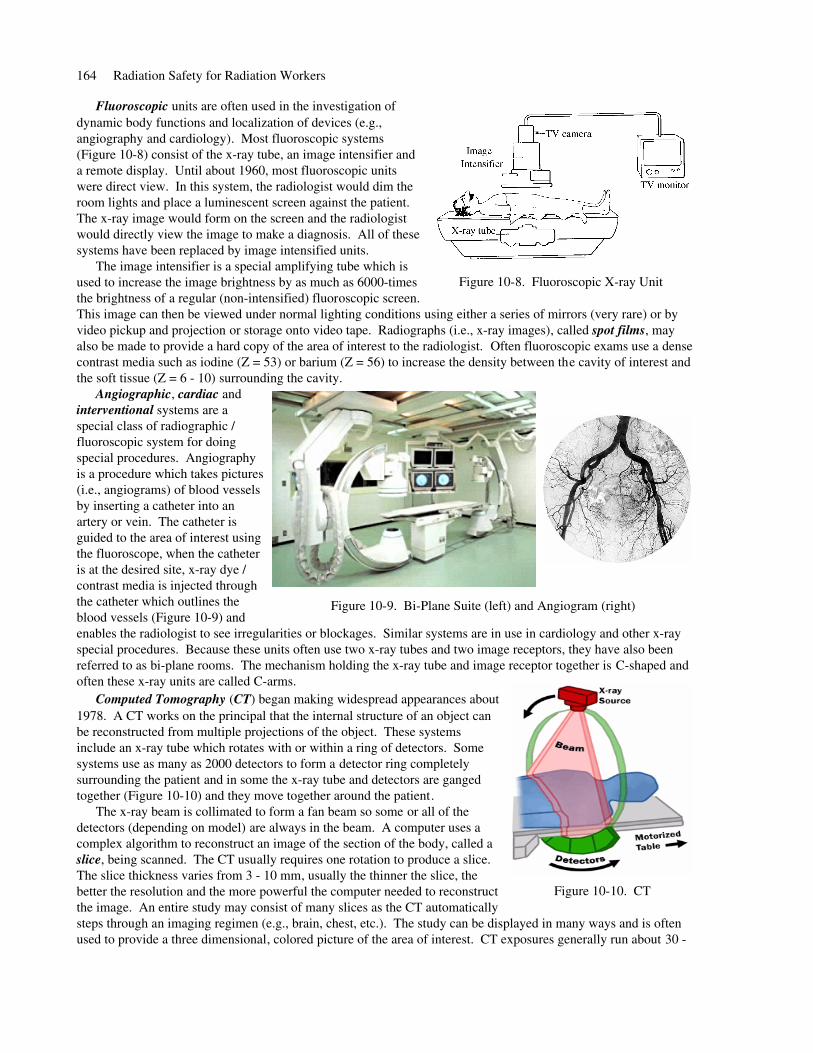
Fluoroscopic units are often used in the investigation ofdynamic body functions and localization of devices (e.g.,angiography and cardiology). Most fluoroscopic systems(Figure 10-8) consist of the x-ray tube, an image intensifier anda remote display. Until about 1960, most fluoroscopic unitswere direct view. In this system, the radiologist would dim theroom lights and place a luminescent screen against the patient.The x-ray image would form on the screen and the radiologistwould directly view the image to make a diagnosis. All of thesesystems have been replaced by image intensified units.
The image intensifier is a special amplifying tube which isused to increase the image brightness by as much as 6000-timesthe brightness of a regular (non-intensified) fluoroscopic screen.This image can then be viewed under normal lighting conditions using either a series of mirrors (very rare) or byvideo pickup and projection or storage onto video tape. Radiographs (i.e., x-ray images), called spot films, mayalso be made to provide a hard copy of the area of interest to the radiologist. Often fluoroscopic exams use a densecontrast media such as iodine (Z = 53) or barium (Z = 56) to increase the density between the cavity of interest andthe soft tissue (Z = 6 - 10) surrounding the cavity.
Angiographic, cardiac andinterventional systems are aspecial class of radiographic /fluoroscopic system for doingspecial procedures. Angiographyis a procedure which takes pictures(i.e., angiograms) of blood vesselsby inserting a catheter into anartery or vein. The catheter isguided to the area of interest usingthe fluoroscope, when the catheteris at the desired site, x-ray dye /contrast media is injected throughthe catheter which outlines theblood vessels (Figure 10-9) andenables the radiologist to see irregularities or blockages. Similar systems are in use in cardiology and other x-rayspecial procedures. Because these units often use two x-ray tubes and two image receptors, they have also beenreferred to as bi-plane rooms. The mechanism holding the x-ray tube and image receptor together is C-shaped andoften these x-ray units are called C-arms.
Computed Tomography (CT) began making widespread appearances about1978. A CT works on the principal that the internal structure of an object canbe reconstructed from multiple projections of the object. These systems include an x-ray tube which rotates with or within a ring of detectors. Somesystems use as many as 2000 detectors to form a detector ring completelysurrounding the patient and in some the x-ray tube and detectors are gangedtogether (Figure 10-10) and they move together around the patient.
The x-ray beam is collimated to form a fan beam so some or all of thedetectors (depending on model) are always in the beam. A computer uses acomplex algorithm to reconstruct an image of the section of the body, called aslice, being scanned. The CT usually requires one rotation to produce a slice.The slice thickness varies from 3 - 10 mm, usually the thinner the slice, thebetter the resolution and the more powerful the computer needed to reconstructthe image. An entire study may consist of many slices as the CT automaticallysteps through an imaging regimen (e.g., brain, chest, etc.). The study can be displayed in many ways and is oftenused to provide a three dimensional, colored picture of the area of interest. CT exposures generally run about 30 -
164 Radiation Safety for Radiation Workers
Figure 10-8. Fluoroscopic X-ray Unit
Figure 10-9. Bi-Plane Suite (left) and Angiogram (right)
Figure 10-10. CT
70 mGy (3 - 7 rad) per slice and, even though the beam is well collimated, because of scatter, an entire scan mayproduce about 50 - 100 mGy (5 - 10 rad) within the area being studied.
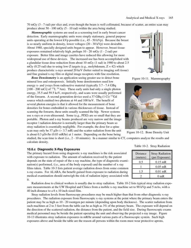
Mammographic systems are used as a screening tool in early breast cancerdetection. Early mammographic units were simply stationary, general purposeunits operating at the lowest kVp possible (i.e., 45 - 50 kVp). Because the breastis so nearly uniform in density, lower voltages (20 - 30 kVp) were desirable.About 1980, specially designed units began to appear. However, breast tissueexposures remained relatively high, perhaps 10 - 20 mGy (1 - 2 rad) perexposure. Better film and image casettes have reduced this allowing for morewidespread use of these devices. The increased use has been accomplished witha glandular tissue dose reduction from about 10 mGy (1 rad) in 1980 to about 2.5mGy (0.25 rad) due to using low-Z targets (e.g., molybdenum, Z = 42) whichproduce characteristic x-rays around 20 keV (better suited to imaging soft tissue)and fine grained x-ray film or digital image receptors with fine resolution.
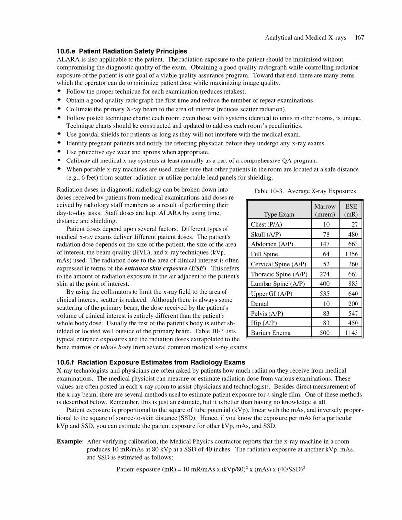
Bone Densitometry is an application seeing greater use to detect bonemineral loss and osteoporosis. Initially bone densitometers used lowenergy x- and γ-rays from radioactive material (typically 3.7 - 7.4 GBq[100 - 200 mCi] of 125I, 241Am). These early units had only a single photonenergy, 35.5 and 59.5 keV, respectively, and scans were usually performedof the forearm. A second generation device used a 37 GBq (1 Ci) 153Gdsource which emitted two photons at 44 and 100 keV. The benefit ofseveral photon energies is that it allowed for the measurement of bonedensities for bones embedded in various thicknesses of tissue. Instead ofscanning the forearm, these units usually scanned the hip. Newer systemsuse x-rays or even ultrasound. Some (e.g., PIXI) are so small that they areportable. Photon and x-ray beams produced are very narrow and the imagereceptor / radiation detector is normally larger than the primary beam sostray radiation is essentially negligible. For example, the dose for a spinescan may only be 37 μSv (~ 3.7 mR) and the scatter radiation from the unitis about 0.3 μSv/hr (0.03 mR/hr) at 1 meter. Depending on the bone beingstudied, the scan time is short (i.e., 2 - 10 minutes). In a manner similar to CT, computers analyze the results andcalculate density.
10.6.c Diagnostic X-Ray ExposuresThe primary hazard from using diagnostic x-ray machines is the risk associatedwith exposure to radiation. The amount of radiation received by the patientdepends on the state of repair of the x-ray machine, the type of diagnostic exami-nation(s) performed, (i.e., area of the body exposed) and the number of x-rayfilms taken. Table 10-3 lists patient average radiation doses from some commonx-ray exams. For ALARA, the benefit gained from exposure to radiation duringmedical examination should outweigh the risk of radiation injury associated withit.
Radiation dose to clinical workers is usually due to stray radiation. Table 10-2 lists typical stray radiation expo-sure measurements at the UW Hospital and Clinics from a mobile x-ray machine set to 90 kVp and 5 mAs, with a40 inch distance to a 6 x 10 inch sized film.
Stray radiation levels from fluoroscopy procedures may be much higher than that from other diagnostic x-rayprocedures. The radiation exposure from fluoroscopic x-ray systems at the point where the primary beam enters thepatient may be as high as 10 - 20 roentgen per minute (depending upon body thickness). The scatter radiation fromsuch machines at 2 to 3 feet from the table can be as high as 3% of the primary beam. The exposure will depend onthe direction of the scattered radiation, the distance from the patient, and the field size. During fluoroscopic examsmedical personnel may be beside the patient operating the unit and observing the projected x-ray image. Figure10-13 illustrates stray radiation exposures in mR/hr around various parts of a fluoroscopic system. Such highexposures above and beside the table are the reason all persons within the room must wear protective aprons,
Analytical and Medical X-rays 165
Figure 10-11. Mammography
Figure 10-12. Bone Density Unit
0 mR2
0.01 mR1.5
0.05 mR1
0.15 mR0.5
Stray Radiation(per Exposure)
Distance(meters)
Table 10-2. Stray Radiation

glasses, and thyroid shields. Protective aprons can absorb 95% or moreof the incident x-ray beam. Some fluoroscopic x-ray units also have alead skirt between the image receptor and the table to reduce the scatterradiation.
Radiation doses to workers are monitored using personal dosimeters(see 7.1). Radiation histories are available from the Radiation SafetyOffice. Radiation protection for technologists and physicians relies onthe factors of time, distance, and shielding. That is: the time spent nearthe machine while it is producing x-rays, the distance between theworker and the x-ray source, and the shielding used by the worker andthat of the tube housing. Increasing the distance and the amount ofshielding, and decreasing the time will decrease the amount of radiationexposure to a worker.
To protect all persons in the vicinity of a radiology facility, therooms are specially designed by a medical physicist whoreviews such factors as the type of x-ray unit, the maximumenergy, the number and type of radiographs, etc. Analyz-ing this information, the room plan includes the quantity ofshielding in the walls, location of the control panel, whetherdoor interlocks are required, etc. For example, Figure10-14 is a plan for a general purpose radiographic / fluoro-scopic x-ray room. Depending upon workload, walls uponwhich the primary beam may be directed usually havebetween and - inches of lead. Other walls in the room1
81
16may have less thick layers of lead sandwiched betweendrywall. The operator normally activates the x-ray beamfrom within a shielded area containing the control paneland a viewing window made of leaded glass.
10.6.d Worker SafetyRadiation exposure to technologists, nursing staff, physicians, and to others must be kept ALARA. Time, distance,and shielding are typically applied to control and reduce radiation exposure.
Only personnel who are required for the x-ray procedures or training should be present in the x-ray room duringexposures. All personnel who must be present in the room during x-ray exposures:
Must wear lead aprons, leaded safety glasses, thyroid shield, leaded gloves as deemed appropriate by theRadiation Safety Officer; or utilize portable or fixed lead panels.Maximize the distance between themselves and the patient as practical. If you do not need to be at thepatient's side, remain a minimum of 6 feet from the tube head.Wear personal dosimeters to monitor radiation exposure. When an apron is worn, one dosimeter must beworn on the collar outside the apron.If your hand must be in or near the primary beam, wear a finger dosimeter and a lead glove. The fingerdosimeter must be worn under the glove.
Keep the time of radiation exposure short especially during fluoroscopy procedures.Follow proper techniques to minimize the number of repeat exposures. Staff should not routinely hold patients. Use mechanical holding devices when a patient or film requires addedsupport or, if not possible, patients should be held by a relative or friend who is wearing lead aprons and gloves.If pregnant, notify your supervisors and request a briefing from Radiation Safety about the Pregnancy Surveil-lance Program. Request Safety Department personnel to evaluate the shielding in all new X-ray machines.If excessive or abnormal radiation exposure is suspected notify Radiation Safety immediately. Keep all dosime-ters available to assist in the investigation.
166 Radiation Safety for Radiation Workers
Figure 10-13. Stray Radiation
Image Intensifier
Fluoro Table
Feet
Fee
t Patient
Figure 10-14. Typical X-ray Room
10.6.e Patient Radiation Safety PrinciplesALARA is also applicable to the patient. The radiation exposure to the patient should be minimized withoutcompromising the diagnostic quality of the exam. Obtaining a good quality radiograph while controlling radiationexposure of the patient is one goal of a viable quality assurance program. Toward that end, there are many itemswhich the operator can do to minimize patient dose while maximizing image quality.
Follow the proper technique for each examination (reduces retakes).Obtain a good quality radiograph the first time and reduce the number of repeat examinations.Collimate the primary X-ray beam to the area of interest (reduces scatter radiation).Follow posted technique charts; each room, even those with systems identical to units in other rooms, is unique.Technique charts should be constructed and updated to address each room’s peculiarities.Use gonadal shields for patients as long as they will not interfere with the medical exam.Identify pregnant patients and notify the referring physician before they undergo any x-ray exams.Use protective eye wear and aprons when appropriate.Calibrate all medical x-ray systems at least annually as a part of a comprehensive QA program..When portable x-ray machines are used, make sure that other patients in the room are located at a safe distance(e.g., 6 feet) from scatter radiation or utilize portable lead panels for shielding.
Radiation doses in diagnostic radiology can be broken down intodoses received by patients from medical examinations and doses re-ceived by radiology staff members as a result of performing theirday-to-day tasks. Staff doses are kept ALARA by using time,distance and shielding.
Patient doses depend upon several factors. Different types ofmedical x-ray exams deliver different patient doses. The patient'sradiation dose depends on the size of the patient, the size of the areaof interest, the beam quality (HVL), and x-ray techniques (kVp,mAs) used. The radiation dose to the area of clinical interest is oftenexpressed in terms of the entrance skin exposure (ESE). This refersto the amount of radiation exposure in the air adjacent to the patient'sskin at the point of interest.
By using the collimators to limit the x-ray field to the area ofclinical interest, scatter is reduced. Although there is always somescattering of the primary beam, the dose received by the patient'svolume of clinical interest is entirely different than the patient'swhole body dose. Usually the rest of the patient's body is either sh-ielded or located well outside of the primary beam. Table 10-3 liststypical entrance exposures and the radiation doses extrapolated to thebone marrow or whole body from several common medical x-ray exams.
10.6.f Radiation Exposure Estimates from Radiology ExamsX-ray technologists and physicians are often asked by patients how much radiation they receive from medicalexaminations. The medical physicist can measure or estimate radiation dose from various examinations. Thesevalues are often posted in each x-ray room to assist physicians and technologists. Besides direct measurement ofthe x-ray beam, there are several methods used to estimate patient exposure for a single film. One of these methodsis described below. Remember, this is just an estimate, but it is better than having no knowledge at all.
Patient exposure is proportional to the square of tube potential (kVp), linear with the mAs, and inversely propor-tional to the square of source-to-skin distance (SSD). Hence, if you know the exposure per mAs for a particularkVp and SSD, you can estimate the patient exposure for other kVp, mAs, and SSD.
Example: After verifying calibration, the Medical Physics contractor reports that the x-ray machine in a roomproduces 10 mR/mAs at 80 kVp at a SSD of 40 inches. The radiation exposure at another kVp, mAs,and SSD is estimated as follows:
Patient exposure (mR) = 10 mR/mAs x (kVp/80)2 x (mAs) x (40/SSD)2
Analytical and Medical X-rays 167
1143500 Barium Enema45083 Hip (A/P)54783 Pelvis (A/P)20010 Dental
640535 Upper GI (A/P)
883400 Lumbar Spine (A/P)
663274 Thoracic Spine (A/P)
26052 Cervical Spine (A/P)
135664 Full Spine
663147 Abdomen (A/P)
48078 Skull (A/P)
2710 Chest (P/A)
ESE(mR)
Marrow(mrem)Type Exam
Table 10-3. Average X-ray Exposures

The estimated patient exposure for the following chest exam technique is:
120 kVp, 400 mA, 0.01 sec, at an SSD of 72 inches
10 mR
mAs x ( 120 kVp80 kVp )2 x 400 mA x 0.01 sec x ( 40 in
72 in )2 = 27.8 mR
10.7 X-Ray RegulationsRadiation producing machines are regulated by Federal and State agencies. The Food and Drug Administration(FDA) regulates manufacturers of electronic systems capable of producing x-rays. The State regulates and licensesthose who use x-ray machines within the State. The Wisconsin Administrative Code, Radiation Protection HFSChapter 157, describes regulations for machines used in the State of Wisconsin.
It is important to know that radiation-producing machines must not be used on humans except for healing arts.Exceptions to this must be secured in writing from the Department of HFS.
All radiation producing machines must be registered with the Department of Health and Family Services(DHFS). All machines used at the University of Wisconsin - Madison, including the Medical School, are registeredby the UW Safety Department. When you purchase a machine capable of producing x-rays, contact Safety at2-8769 so the necessary registrations can be accomplished.
If these systems are replaced or broken, they may be disposed of as "junk" provided: (1) the tube head isrendered inoperable, and (2) the person responsible for the system has notified the Safety Department who will thentell the Department of Health and Family Service that the system will be disposed. Working systems may be trans-ferred or sold to other medical/research activities or electronic repair activities provided the Safety Department firstnotifies the Department of Health and Family Service. Because some of these systems manufactured before 1980may have PCB (polychlorinated biphenyl) oil in their transformer, if you see oil leaking from your system or desireto dispose of it, call Safety (262-8769) to sample the oil free of charge.
If you have any questions regarding regulations of radiation producing machines or you wish to obtain a copy ofChapter HFS 157 call the UW-Safety Department.
10.8 Review Questions - Fill in or select the correct response1. Excessive (more than 300 rad) exposure from "soft" x-rays can produce .
2. The basic protection principles are , , and .
3. The transformer oil in older analytical x-ray systems may contain asbestos / PCBs.
4. Do / Do not intentionally by-pass any safety device or interlock without the approval of the person in controlof the system.
5. A warning light labeled must be located near any switch which energizes an x-ray tube.
6. Each room containing x-ray equipment must be posted with a sign which states: .
7. If a safety device has been by-passed, a sign must be conspicuously posted stating: .
8. Stray radiation is the sum of the and the radiation.
9. In producing x-rays, most of the electron beam energy is dissipated as .
10. The effective energy of the K - characteristic x-rays from tungsten is keV.
11. Wear protective aprons if you must be present in a room during x-ray exposure. true / false12. The tube current determines the number of produced while the tube potential (kVp) determines
the of the x-rays produced.13. Two types of electron microscopes are the and electron microscope.
14. Call Radiation Safety (262-8769) if you buy or will buy a new x-ray producing system. true / false
10.9 ReferencesBushong, S.C., Radiologic Science for Technologists, 4th ed., The C.V. Mosby Co, St. Lousi, MO, 1988Curry, T.S., III, Dowdey, J.E., and Murry, R.C., Jr., Christensen’s Physics of Diagnostic Radiology, 4th ed., Lea &Febiger, Philadelphia, PA, 1990National Council on Radiation Protection and Measurements, NCRP Report No. 32: Radiation Protection in Educa-tional Institutions, NCRP Publications, Washington, D.C., 1966
168 Radiation Safety for Radiation Workers