1 xdsl technical overview oct 08. 2 dsl market drivers & enablers service provider drivers ...
TRANSCRIPT
1
xDSL
Technical OverviewOct 08

2
DSL Market Drivers & Enablers
Service Provider Drivers Telco's desire to compete with
Cable companies Additional service(s) = revenue
SAI
IP DSLAM
B-Box / SAI VDSL over OSP Twisted Pair
NID/SplitterPOTS
Res. Gateway
STB
STB
STB
Consumer drivers IPTV More upstream data High-speed internet data Consolidated billing
Enablers IC Technology advancements Leverage ADSL and extend
frequency range/bitrate ITU standards finalized
NID/Splitter
OR
ADSL over OSP Twisted Pair
CO

3
DMT
4.3125 Khz
Discrete Multi-ToneEach one is controlled by the DSL protocol based on actual line conditions.
Vf Upstream DownstreamMHz
4.3125 Khz passbandOne sub-carrier, “tone” =
DMT uses 256 “tones” to carry bits/data for ADSL, 4096 for VDSL2
Each “tone” can carry up to 15 bits (QAM)
15 Max
BITS/TONE
4
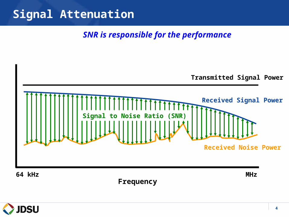
Signal Attenuation
Received Noise Power
Received Signal Power
Transmitted Signal Power
FrequencyMHz64 kHz
Signal to Noise Ratio (SNR)
SNR is responsible for the performance

5
Bits per Tone
Received Noise Power
Received Signal Power
Transmitted Signal Power
FrequencyMHz64 kHz
With good SNR we got more BitsBits per tone
15
0
As distance increases from the DSLAM, signals attenuate on the copper loop reducing difference between noise and the signal restricting the number of bits each DMT carrier can support.
. . .
6
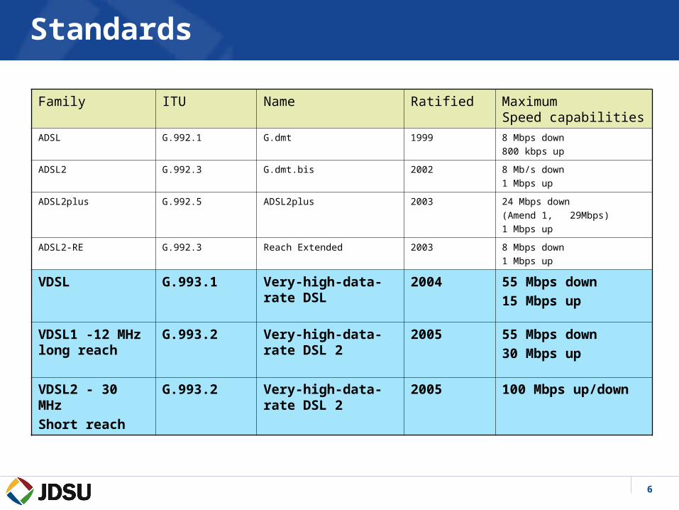
Standards
Family ITU Name Ratified MaximumSpeed capabilities
ADSL G.992.1 G.dmt 1999 8 Mbps down
800 kbps up
ADSL2 G.992.3 G.dmt.bis 2002 8 Mb/s down
1 Mbps up
ADSL2plus G.992.5 ADSL2plus 2003 24 Mbps down
(Amend 1, 29Mbps)
1 Mbps up
ADSL2-RE G.992.3 Reach Extended 2003 8 Mbps down
1 Mbps up
VDSL G.993.1 Very-high-data-rate DSL
2004 55 Mbps down
15 Mbps up
VDSL1 -12 MHz long reach
G.993.2 Very-high-data-rate DSL 2
2005 55 Mbps down
30 Mbps up
VDSL2 - 30 MHz
Short reach
G.993.2 Very-high-data-rate DSL 2
2005 100 Mbps up/down

7
ADSL - VDSL Frequency Ranges & Rates
25kHz 1.1MHz 2.2MHz 12MHz Frequency 30MHz
ADSL2+
ADSL
VDSL
VDSL2
Technology Freq range Max Rates Max # of carriers and
Bin spacing
ADSL 25kHz – 1.1MHz 800kbps up
8Mbps down
256 with 4.3125kHz bins
ADSL2+ 25kHz – 2.2MHz 1Mbps up
24Mbps down
512 with 4.3125kHz bins Amend. 1 = 29 Mbps down
VDSL(1) 25kHz – 12MHz 15Mbps up
55Mbps down
2782 with 4.3125kHz bins
VDSL2 25khz – 30MHz 100Mbps up
100Mbps down
4096 with 4.3125kHz bins
3478 with 8.625kHz bins
Te
ch
no
log
y
17.66MHz

8
What are VDSL2 – Key Features
– Improvements to initialization, including a Channel Discovery phase and a Loop Diagnostics mode
– Improved framing based G.992.3 (ADSL2) with improved overhead channel
– Support of Impulse Noise Protection (INP) up to 16 symbols– Support for a MIB-Controlled PSD mask mechanism for in-band
spectral shaping– Support for an optional extension of the USO band to 276 kHz– Improved FEC capabilities, including a wider range of settings for the
Reed-Solomon encoder and the inter-leaver

9
ADSL2+/VDSL/VDSL2 - Rate versus Reach
0
50
100
150
200
250
0 500 1000 1500 2000 2500 3000 3500Reach / m
Rat
e / M
Bit
/s
DS ADSL2+ (2.2 MHz)
DS VDSL1 (12 MHz)
DS VDSL2 (30MHz)
AWGN/-140dBm/Hz/ANSI-TP1
Symmetrical 100Mbit/s due to 30MHz spectrum
ADSL-like long reach performance due to Trellis coding and Echo Cancellation
Improved mid range performance through Trellis coding and Generic Convolutional Interleaver
1600 3300 4900 6600 8200 9900 11,500Reach / ft*

10
0 1 2 3 4 5 60
20
40
60
80
100
120
140
Loop Length (kft)
Rate
(M
bits/s
)
AWG26, Gap = 12dB, 20-self, Tx PSD = -53 dBm/Hz
30 MHz 25 MHz 20 MHz 17.6 MHz12 MHz 8.5 MHz 4.4 MHz 2.2 MHz 1.1 MHz
VDSL Rate and Reach

11
Bonded Service
A way to increase rate and reach over single pair limitations Multiple physical pairs carrying a portion of the total bit
stream. Three approaches:
– G.998.1, ATM based– G.998.2, Ethernet based– G.998.3 Time –division Inverse Mux
VDSL will use an Ethernet approach with “muxing” at the TC layer with a new aggregation and rate matching function.
May not achieve double the rates due to VDSL cross talk in the same binder group

12
Ham Radio Notches
13
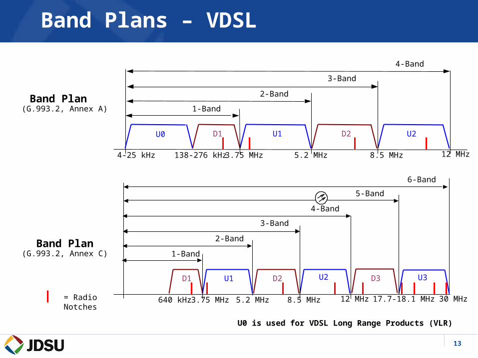
Band Plan (G.993.2, Annex A)
Band Plan(G.993.2, Annex C)
U0 is used for VDSL Long Range Products (VLR)
Band Plans – VDSL
D1 U1 D2
138-276 kHz 3.75 MHz 5.2 MHz 8.5 MHz
U0
4-25 kHz 12 MHz
2-Band
3-Band
4-Band
U2
1-Band
D1 U1 D2
640 kHz 3.75 MHz 5.2 MHz 8.5 MHz 12 MHz
2-Band
3-Band
4-Band
U2
1-Band
U3D3
17.7-18.1 MHz 30 MHz
5-Band
6-Band
= Radio Notches

14
Band Plan 998(G.993.2, Annex B)
Band Plan 997(G.993.2, Annex B)
U0 is used for VDSL Long Range Products (VLR)
Band Plans – VDSL
D1 U1 D2
138-276 kHz 3.75 MHz 5.2 MHz 8.5 MHz
U0
25 kHz 12 MHz
1-Band
2-Band
3-Band
4-Band
U2
D1 U1 D2
138-276 kHz 3.0 MHz 5.1 MHz 7.05 MHz
U0
25 kHz 12 MHz
2-Band
3-Band
4-Band
U2
1-Band
= Radio Notches
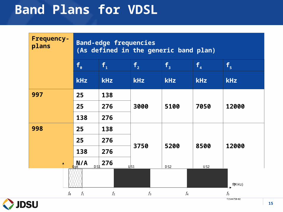
15
Frequency-plans
Band-edge frequencies (As defined in the generic band plan)
f0 f1 f2 f3 f4 f5
kHz kHz kHz kHz kHz kHz
997 25 138
3000 5100 7050 1200025 276
138 276
998 25 138
3750 5200 8500 1200025 276
138 276
N/A 276
T1544750-02
f3f2
DS2
f(MHz)
f1
DS1 US1 US2
f4 f5
Opt
f0
Band Plans for VDSL

16
VDSL2 Profiles
• Profiles are specified to allow transceivers to support a subset of the allowed settings and still be compliant with the recommendation.
• The specification of multiple profiles allows vendors to limit implementation complexity and develop implementations that target specific service requirements.
• The eight VDSL2 profiles (G.993.2):
8a, 8b, 8c, 8d, 12a, 12b, 71a, 30a,
define a set of configurations for transmit power and band plan.• Service Providers are now using these terms

17
VDSL2 Some Favored Profiles
Note: While Annex C is specified as for Japan, other regions are using those profiles

18
VDSL2 Spectrum Capability
• For exchange deployment
– VDSL2 spectrally compatible with ADSL/ADSL2 (138kHz to 1.104MHz) and with ADSL2+ (138kHz to 2.208MHz)
• For cabinet deployment
– VDSL2 spectrally compatible with cabinet-based ADSL2+
– Power control needed to ensure spectrum compatibility with exchange based services (138kHz to 2.208MHz)
– Achieved by shaping the cabinet signals by a factor based on the electrical distance between the exchange and cabinet
– Degree of shaping defined via MIB control (G.997.1)
– Enables VDSL2 to comply with regulatory requirements
– VDSL2 PSD shaping currently being investigated by various European and Asian operators
19
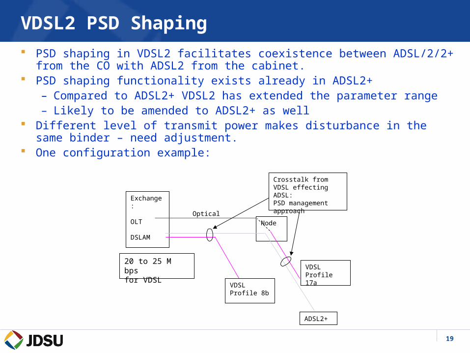
VDSL2 PSD Shaping
PSD shaping in VDSL2 facilitates coexistence between ADSL/2/2+ from the CO with ADSL2 from the cabinet.
PSD shaping functionality exists already in ADSL2+– Compared to ADSL2+ VDSL2 has extended the parameter range– Likely to be amended to ADSL2+ as well
Different level of transmit power makes disturbance in the same binder – need adjustment.
One configuration example:
Exchange:
OLT
DSLAMNode
VDSLProfile 8b
VDSLProfile 17a
Optical
ADSL2+
20 to 25 M bps for VDSL
Crosstalk from VDSL effecting ADSL:PSD management approach

20
OLR - Dual Latency (Fast and Interleaved Paths)
Dual Latency refers to bearer channels that can have different latency treatments as defined by such things as interleave depth, INP settings
and FEC configurations.
Fast path has low latency (<1ms).– Good for voice traffic.– People perceive delay negatively during a conversation.– Losing (small amounts of) data is not critical. Most CODECs will
disguise lost data by replaying the previous audio.
Interleaved path has more latency (up to 10ms) but has better immunity to disturbers such as impulses.– Guaranteed to correct errors due to impulses <250μs.– Good for data and video.– Data and video are tolerant of delay (not "delay variation" that's
jitter) but are not tolerant of lost data
21
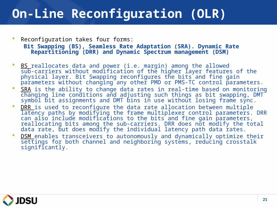
On-Line Reconfiguration (OLR)
Reconfiguration takes four forms: Bit Swapping (BS), Seamless Rate Adaptation (SRA). Dynamic Rate
Repartitioning (DRR) and Dynamic Spectrum management (DSM)
BS reallocates data and power (i.e. margin) among the allowed sub‑carriers without modification of the higher layer features of the physical layer. Bit Swapping reconfigures the bits and fine gain parameters without changing any other PMD or PMS‑TC control parameters.
SRA is the ability to change data rates in real-time based on monitoring changing line conditions and adjusting such things as bit swapping, DMT symbol bit assignments and DMT bins in use without losing frame sync.
DRR is used to reconfigure the data rate allocation between multiple latency paths by modifying the frame multiplexer control parameters. DRR can also include modifications to the bits and fine gain parameters, reallocating bits among the sub-carriers. DRR does not modify the total data rate, but does modify the individual latency path data rates.
DSM enables transceivers to autonomously and dynamically optimize their settings for both channel and neighboring systems, reducing crosstalk significantly.
22
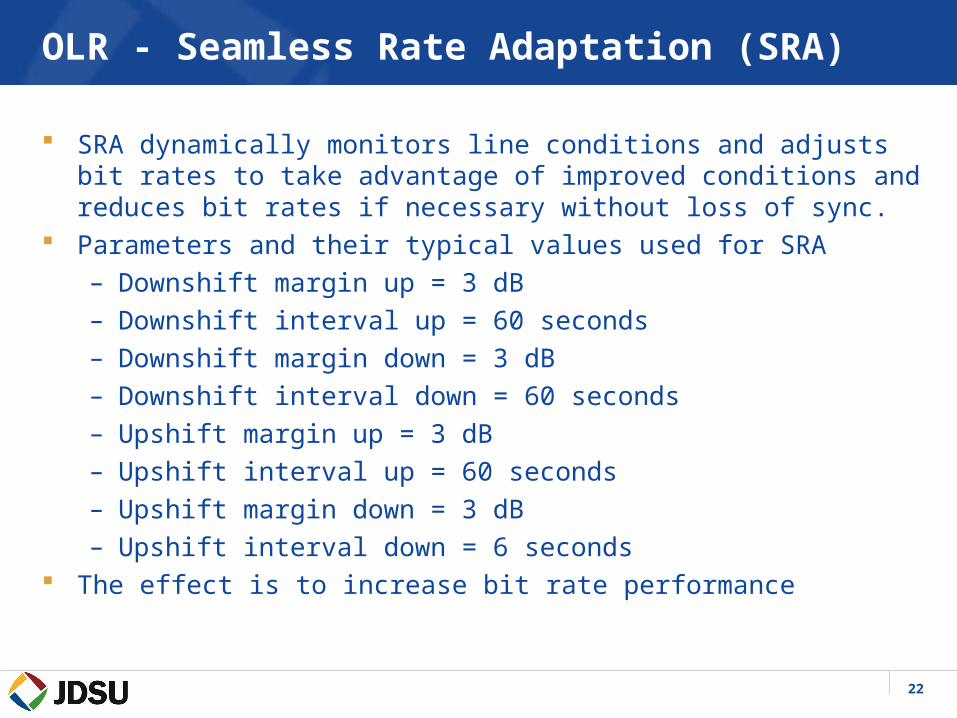
OLR - Seamless Rate Adaptation (SRA)
SRA dynamically monitors line conditions and adjusts bit rates to take advantage of improved conditions and reduces bit rates if necessary without loss of sync.
Parameters and their typical values used for SRA– Downshift margin up = 3 dB– Downshift interval up = 60 seconds– Downshift margin down = 3 dB– Downshift interval down = 60 seconds– Upshift margin up = 3 dB– Upshift interval up = 60 seconds– Upshift margin down = 3 dB– Upshift interval down = 6 seconds
The effect is to increase bit rate performance
23
OLR - Dynamic Rate Repartitioning (DRR)
DRR monitors the bandwidth on a connection and reallocates the bandwidth per path allowing the available bandwidth to be used more efficiently. – It achieves this by modifying the framing parameters and by using
bit swapping. – The reallocation of the bandwidth is done seamlessly without
disturbing the user’s applications (video stream, VoIP call, surfing the net).
– The total delivered bandwidth is not changed. It will reallocate the bandwidth assuring each application gets the highest possible QOS.

24
Dynamic Spectrum Management (DSM) Static Spectrum Management (SSM) setup as part of network engineering
guarantees that all of the DSL lines in binder are spectrally compatible. Since services running on the DSL lines are dynamic, static management typically wastes bandwidth.
DSM takes advantage of dynamically changing conditions and improves the wasted channel capacity left by SSM.
The ultimate DSM solution requires monitoring of the line conditions by a central processing unit as well as the individual modems monitoring line conditions as well.
The central DSM unit monitors:– Line margin– Tx Power Levels– Bits/tone tables– Insertion loss/tone– Noise/tone– Actual PSD levels/tone– Errored seconds– Known service items such as bridge taps, loop lengths, and binder service
area (so they know what other services are in the same binder)
25
Dynamic Spectrum Management (DSM)
There are 4 levels of DSM coordination between multiple DSL lines– Level 0 Static Spectrum Management (SSM)
– Level 1 Autonomous power allocation (Single –user)
– Level 2 Coordinated power allocation (Multi – user)
– Level 3 Multi-pair, multiple-input, multiple-output (MIMO)
26
DSM (The Four Levels) Level 0
Level 0: The performance of one individual pair is optimized without considering the other pairs in the binder
– Rate Adaptive (RA) and Margin Adaptive (MA) modes of operation.
• RA mode – All available power is used to maximize rate at the required margin
• MA mode – All available power is used to maximize margin at a fixed rate.

27
OLR – DSM (The Four Levels) Level 1
Level 1: Each pair in a binder manages power so as to avoid crosstalk with the other pairs in the binder. This will lead to an increased total capacity in the binder.– Power Adaptive (PA) or Fixed Margin (FM) and Iterative
Water Filling (IWF) are modes of operation.• PA – Power is minimized while maintaining a fixed rate and
noise margins that are specified in a given range.• IWF – Very similar to PA except IMF does not adhere to a fixed
PSD, therefore ‘boosting’ is allowed. IWF can increase the power in used tones by reallocating power from unused tones.

28
OLR – DSM (The Four Levels) Level 2
Level 2: Similar to level 1; Here however, the central DSM center considers the other pairs line conditions as well.– Optimal Spectrum Management (OSM) aka Optimal
Spectrum Balancing (OSB)• The central DSM knows the cross-talk paths, the loop lengths,
and the service requirements of each pair in the binder. All the used spectra is optimized by the central DSM by setting the PSDMASK parameters for each pair based on the DSM prediction of the complete binder performance. So for example, a short line may be told to use the higher frequencies even though the lower frequencies would have been used if only IWF was applied.
29
OLR – DSM (The Four Levels) Level 3
Level 3: The central DSM processes all of the signals from all the pairs in a binder at once. All transmitters and/or receivers must be co-located.
– The central DSM will jointly process all of the signals in the binder rather than processing each line individually.
– The binder is considered a whole entity aka (MIMO or vectoring). All the signals are combined into a vectored signal and processed together. With the joint processing, it is now possible to predict the induced crosstalk on the other lines. That predicted crosstalk signal can be subtracted from the actual received signal to reduce the crosstalk.
– This can be implemented in a point-to-point configuration or a point-to-multipoint configuration.
• Point-to-point – All processing is done at the receiver.• Point-to-multipoint – One CO multiple CPE all processing is done at the CO.

30
OLR – Dynamic Spectrum Management (DSM)

31
Impulse Noise Protection
The basic idea with INP is to separate (in time) the data and the corresponding error correction bytes for that data. This helps ensure that if an impulse occurs at time t0 only the data will be corrupted; the RS correction bytes allow the data to be fixed.
– More memory is needed to store the data while waiting for the error correction data.– INP causes the data to be delayed.
Frame #1
Time
Frame #2 Frame #3 Frame #4 Frame #5 Frame #6
Error corr-ection for Frame #1
Error corr-ection for Frame #2
Error corr-ection for Frame #3
Error corr-ection for Frame #4
Error corr-ection for Frame #5
Error corr-ection for Frame #6
Frame #1 Frame #2 Frame #3 Frame #4 Frame #5 Frame #6
Error corr-ection for Frame #1
Error corr-ection for Frame #2
Error corr-ection for Frame #3
Error corr-ection for Frame #4
Error corr-ection for Frame #5
Line 1
Line 2
X
X
X X
X
X
32
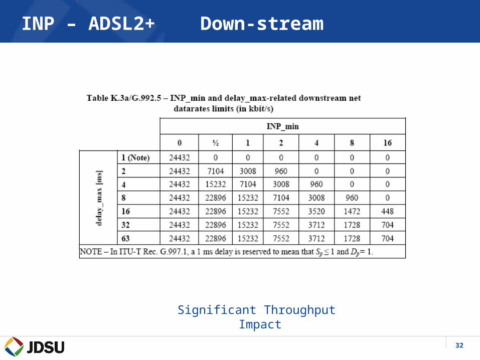
INP – ADSL2+ Down-stream
Significant Throughput Impact
33
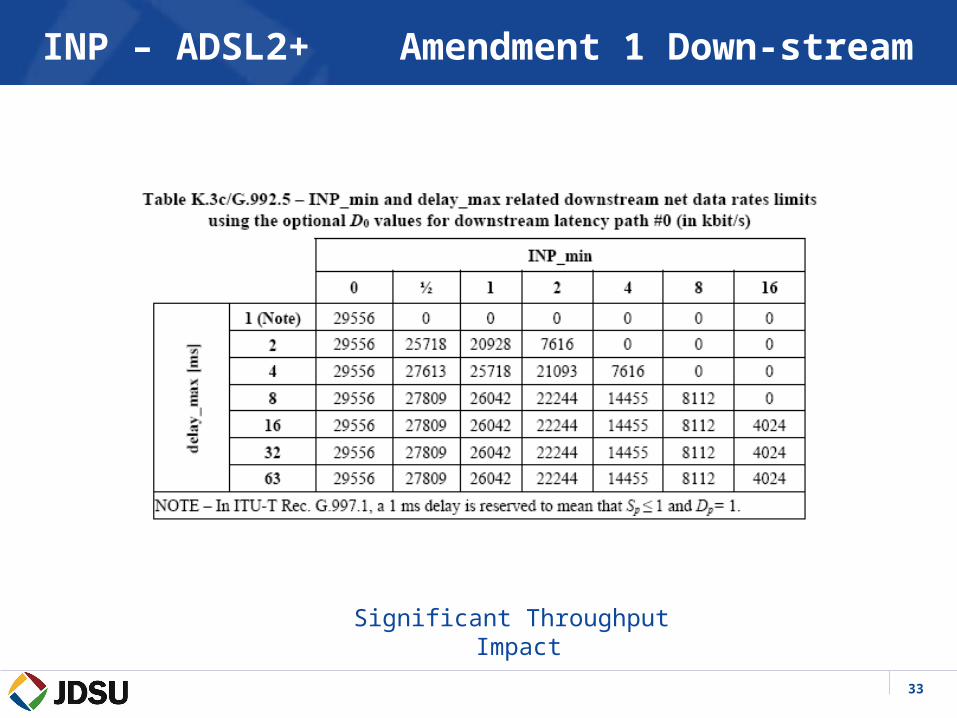
INP – ADSL2+ Amendment 1 Down-stream
Significant Throughput Impact
34
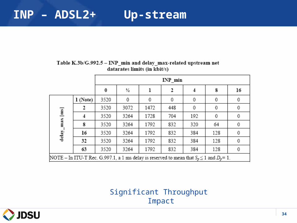
INP – ADSL2+ Up-stream
Significant Throughput Impact

35
Impulse Noise Impairments
VDSL is more susceptible to impulse noise events due to it’s use of a wider frequency spectrum than ADSL. Noise sources are being analyzed in several forms:– REIN (Repetitive Electrical Impulse Noise)
• Less than 1 ms in duration• No bit errors desired• INP mitigation
– PEIN (Prolonged Electrical Impulse Noise)• 1 to 10 ms in duration• No bit errors desired• INP mitigation
– SHINE (Single Isolated Impulse Noise Event)• Duration greater than 10 ms• Due to duration of events, bit errors will typically occur• No loss of sync is desired
36
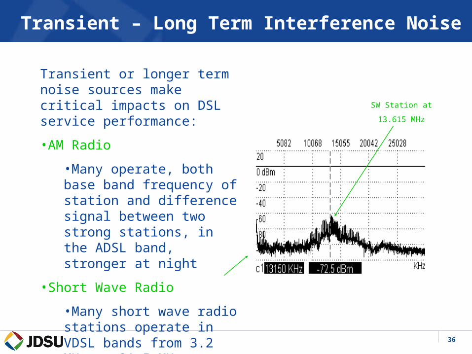
Transient – Long Term Interference Noise
Transient or longer term noise sources make critical impacts on DSL service performance:
•AM Radio
•Many operate, both base band frequency of station and difference signal between two strong stations, in the ADSL band, stronger at night
•Short Wave Radio
•Many short wave radio stations operate in VDSL bands from 3.2 MHz to 21.5 MHz
SW Station at
13.615 MHz

37
-90
-80
-70
-60
-50
-40
-30
-20
-10
0
0 1 2 3 4 5 6 7 8 9 10
Freq (MHz)
Inse
rtio
n L
oss
(d
B)
Clean pair
44ft tap
A tap acts like a filter
38
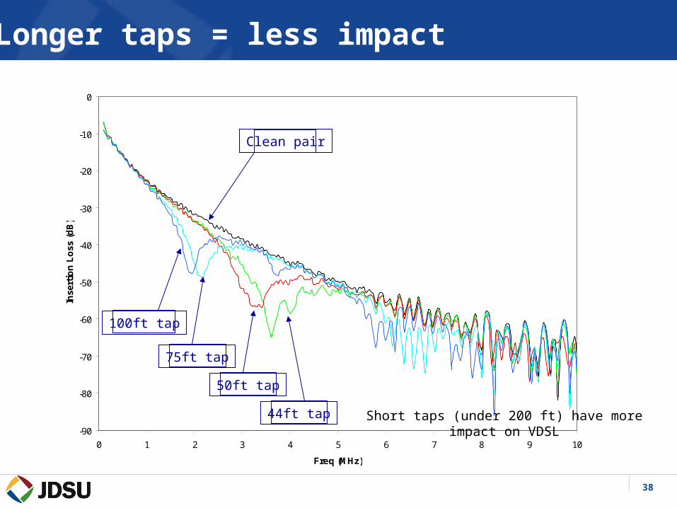
-90
-80
-70
-60
-50
-40
-30
-20
-10
0
0 1 2 3 4 5 6 7 8 9 10
Freq (MHz)
Inse
rtio
n L
oss
(d
B)
Clean pair
100ft tap
75ft tap
50ft tap
44ft tap
Longer taps = less impact
Short taps (under 200 ft) have more impact on VDSL