1. soil resistivity testing - ver pangonilo 1. soil resistivity testing 1.1 introduction it is well...
TRANSCRIPT
Earthing Techniques
1. SOIL RESISTIVITY TESTING....................................................................................................................................
1.1 INTRODUCTION.................................................................................................................................................................
1.2 THEORY OF SOIL RESISTIVITY......................................................................................................................................
1.3 MAKING A MEASUREMENT ........................................................................................................................................... 1.3.1 PRINCIPLES...............................................................................................................................................................4 1.3.2 SOIL RESISTIVITY TESTING PROCEDURE GUIDELINES ..................................................................................
(a) Test Method.................................................................................................................................................................. (b) Selection of Test Method Type .................................................................................................................................... (c) Traverse Locations. ...................................................................................................................................................... (d) Spacing Range.............................................................................................................................................................. (e) Practical Testing Recommendations.........................................................................................................................10
2. INTERPRETATION AND MODELLING OF RESULT...........................................................................................11
2.1 APPARENT RESISTIVITY CALCULATION................................................................................................................11
2.2 INTERPRETATION OF RESISTIVITY MEASUREMENT...........................................................................................12
3. HOW TO DESIGN A LIGHTNING EARTH SYSTEM ............................................................................................14
3.1 TYPES OF EARTH ELECTRODES................................................................................................................................14
3.2 COMMON EARTHING SYSTEMS ................................................................................................................................14
3.3 EARTH RESISTANCE OF AN ELECTRODE - CALCULATION................................................................................16 3.3.1 Rods Driven Vertically into the Ground....................................................................................................................16 3.3.2 Rod Electrodes in Parallel .........................................................................................................................................16 3.3.3 Trench Electrodes - Horizontal Electrodes buried under the Surface........................................................................17 3.3.4 Radial Conductors .....................................................................................................................................................18 3.3.5 Ground-grid Mesh Electrodes....................................................................................................................................19
3.4 RECOMMENDED MATERIAL APPLICATIONS.........................................................................................................19
4. TESTING AN EARTHING SYSTEM ......................................................................................................................21
4.1 EARTH RESISTANCE OF AN ELECTRODE - MEASUREMENT..............................................................................21 4.1.1 Fall of Potential Method ............................................................................................................................................22 4.1.2 The 62% Method .......................................................................................................................................................24 4.1.3 Other Test Methods ...................................................................................................................................................24
(a) The Slope Method ....................................................................................................................................................24 (b) The Star-Delta Method.............................................................................................................................................24 (c) The Four Potential Method.......................................................................................................................................25
5. THE SIGNIFICANCE OF IMPEDANCE.................................................................................................................26
5.1 INTRODUCTION.............................................................................................................................................................26
5.2 THEORY...........................................................................................................................................................................27
Earthing Fundamentals Lightning & Surge Technologies
5.2.1 Impulse Testing And The Transient Response ..........................................................................................................27 5.2.2 Assessing the transient performance of an earthing system ......................................................................................27 5.2.3 The Impulse Impedance.............................................................................................................................................29 5.2.4 Definition of the Impulse Impedance ........................................................................................................................30 5.2.5 Interpreting Impulse Impedance Measurements ........................................................................................................30 5.2.6 Variations in the Impulse Impedance within an earthing system ..............................................................................30 5.2.7 Comparing Impulse Impedance and DC Resistance values.......................................................................................31 5.2.8 Selective Earth Testing in Interconnected Earth Systems .........................................................................................31
5.3 CONCLUSIONS...............................................................................................................................................................33
6. PRACTICAL EARTH SYSTEM ANALYSIS ..........................................................................................................34
6.1 APPLICATION EXAMPLES...........................................................................................................................................34 6.1.1 Satellite Ground Station.............................................................................................................................................34 6.1.2 Marine Communications Centre ................................................................................................................................35 6.1.3 PABX lightning induced damage ..............................................................................................................................36 6.1.4 Cellular radio site.......................................................................................................................................................36 6.1.5 A mountain top site for Civil Aviation Communications ..........................................................................................37
7. IMPROVING AN EARTHING SYSTEM .................................................................................................................38
7.1 FACTORS TO CONSIDER..............................................................................................................................................38
7.2 EXAMPLES OF ACHIEVING SUITABLE EARTHING INSTALLATIONS USING CHEMICAL ADDITIVES.....39 7.2.1 Example 1 ..................................................................................................................................................................39 7.2.2 Example 2 ..................................................................................................................................................................39 7.2.3 Example 3 ..................................................................................................................................................................39 7.2.4 Example 4 ..................................................................................................................................................................39
7.3 NOTES ON THE APPLICATION OF CHEMICAL COMPOUNDS..............................................................................39 7.3.1 Measures For Reducing The Impulse Impedance......................................................................................................40
7.4 WHAT TO DO IN EXTREME CASES ?.........................................................................................................................40
Page 2 of 40
Earthing Fundamentals Lightning & Surge Technologies
1. Soil Resistivity Testing
1.1 INTRODUCTION It is well known that the resistance of an earth electrode is heavily influenced by the resistivity of the soil in which it is driven and as such, soil resistivity measurements are an important parameter when designing earthing installations. A knowledge of the soil resistivity at the intended site, and how this varies with parameters such as moisture content, temperature and depth, provides a valuable insight into how the desired earth resistance value can be achieved and maintained over the life of the installation with the minimum cost and effort.
One of the main objectives of earthing electrical systems is to establish a common reference potential for the power supply system, building structure, plant steelwork, electrical conduits, cable ladders & trays and the instrumentation system. To achieve this objective, a suitable low resistance connection to earth is desirable. However, this is often difficult to achieve and depends on a number of factors:
• Soil resistivity • Stratification • Size and type of electrode used • Depth to which the electrode is buried • Moisture and chemical content of the soil Section 1.2 covers the first of these points.
1.2 THEORY OF SOIL RESISTIVITY Resistance is that property of a conductor which opposes electric current flow when a voltage is applied across the two ends. Its unit of measure is the Ohm (Ω) and the commonly used symbol is R. Resistance is the ratio of the applied voltage (V) to the resulting current flow (I) as defined by the well known linear equation from Ohm’s Law:
V I R= ×
where: V Potential Difference across the conductor (Volts) I Current flowing through the conductor in (Amperes) R Resistance of the conductor in (Ohms)
“Good conductors” are those with a low resistance. “Bad conductors” are those with a high resistance. “Very bad conductors” are usually called insulators.
The Resistance of a conductor depends on the atomic structure of the material or its Resistivity (measured in Ohm-m or Ω-m), which is that property of a material that measures its ability to conduct electricity. A material with a low resistivity will behave as a “good conductor” and one with a high resistivity will behave as a “bad conductor”. The commonly used symbol for resistivity is ρ (Greek symbol rho).
The resistance (R) of a conductor, can be derived from the resistivity as:
Page 3 of 40
Earthing Fundamentals Lightning & Surge Technologies
RL
=×ρA
here ρ Resistivity (Ω-m) of the conductor material
etween the opposite faces of a cube of material with a side dimension of 1 metre.
Consequently, is the measure of the resistance between the opposite sides of a cube of soil with a side dimension of 1 metre.
Ω Ω Ω
T When designing an earthing system to meet safety and reliability criteria, an accurate resistivity model of
following sections outline the major practical aspects of the measurement
lues in the Australian continent are widely varying depending on the type of terrain, eg, rder of 1.5Ωm, whereas dry sand or granite in
fect resistivity may be
• • n; layers of different types of soil (eg, loam backfill on a clay base).
, after a ith content greater than 40% do not occur
• ture; above freezing point, the effect on earth resistivity is practically negligible.
• able ducts, rail tracks, metal pipes and fences. Topography; rugged topography has a similar effect on resistivity measurement as local surface resistivity variation caused by weathering and moisture.
w L Length of the conductor (m) A Cross sectional Area (m2)
Resistivity is also sometimes referred to as “Specific Resistance” because, from the above formula, Resistivity (Ω-m) is the resistance b
Soil Resistivity
In the USA, a measurement of -cm is used. (100 -cm = 1 -m)
1.3 MAKING A MEASUREMEN
the soil is required. Theprocedure and result interpretation.
1.3.1 PRINCIPLES Soil resistivity vasilt on a river bank may have resistivity value in the omountainous country areas may have values higher than 10,000Ωm. Factors that afsummarised as:-
Type of earth (eg, clay, loam, sandstone, granite). Stratificatio
• Moisture content; resistivity may fall rapidly as the moisture content is increased, howevervalue of about 20% the rate of decrease is much less. Soil wvery often. Tempera
• Chemical composition and concentration of dissolved salt. Presence of metal and concrete pipes, tanks, large slabs, c
•
Page 4 of 40
Earthing Fundamentals Lightning & Surge Technologies
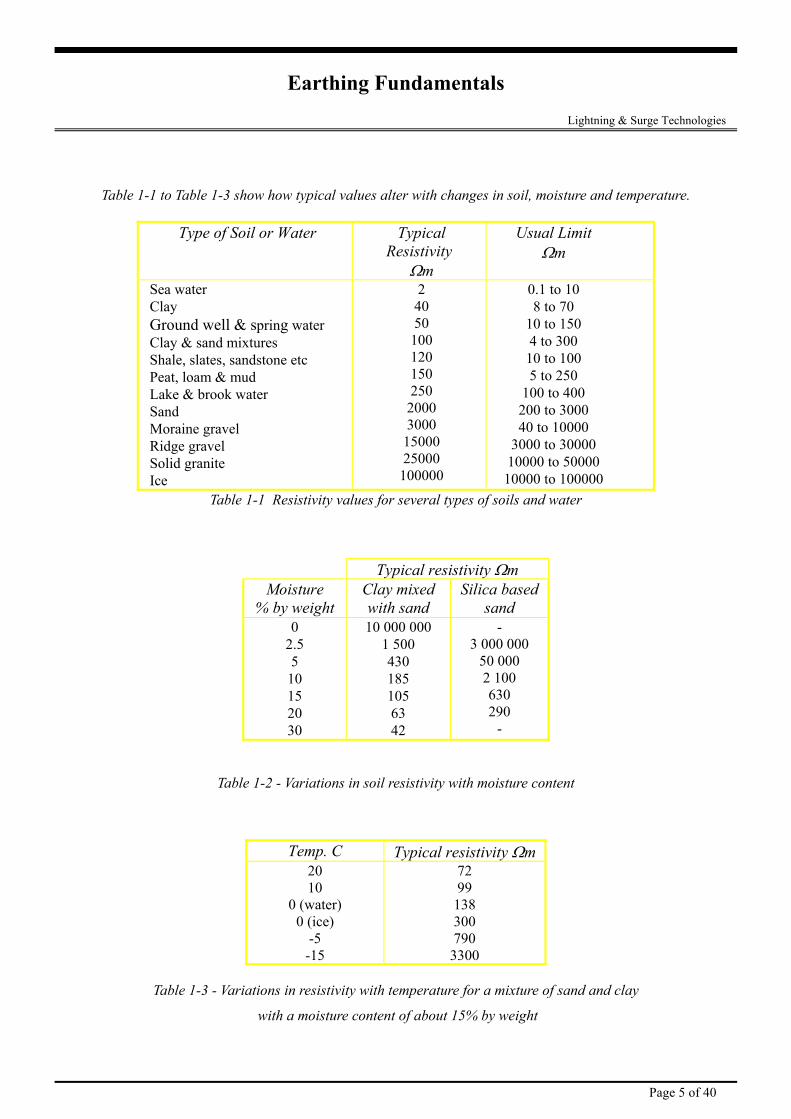
Table 1-1 to Table 1-3 show how typical values alter with changes in soil, moisture and temperature.
Table 1-1 Resistivity values for several types of soils and water
Type of Soil or Water Typical Resistivity
Ωm
Usual Limit Ωm
Sea water Clay Ground well & spring water Clay & sand mixtures Shale, slates, sandstone etc Peat, loam & mud Lake & brook water Sand Moraine gravel Ridge gravel Solid granite Ice
2 40 50
100 120 150 250
2000 3000
15000 25000
100000
0.1 to 10 8 to 70
10 to 150 4 to 300
10 to 100 5 to 250
100 to 400 200 to 3000 40 to 10000
3000 to 30000 10000 to 50000
10000 to 100000
Typical resistivity Ωm Moisture
% by weight Clay mixed with sand
Silica based sand
0 2.5 5
10 15 20 30
10 000 000 1 500 430 185 105 63 42
- 3 000 000
50 000 2 100 630 290
-
Table 1-2 - Variations in soil resistivity with moisture content
Temp. C Typical resistivity Ωm 20 10
0 (water) 0 (ice)
-5 -15
72 99
138 300 790
3300
Table 1-3 - Variations in resistivity with temperature for a mixture of sand and clay
with a moisture content of about 15% by weight
Page 5 of 40
Earthing Fundamentals Lightning & Surge Technologies
Typical resistivity Ωm
0
500
1000
1500
2000
2500
3000
3500
-15 -5 0 (ice) 0 (water) 10 20
Temperature °C
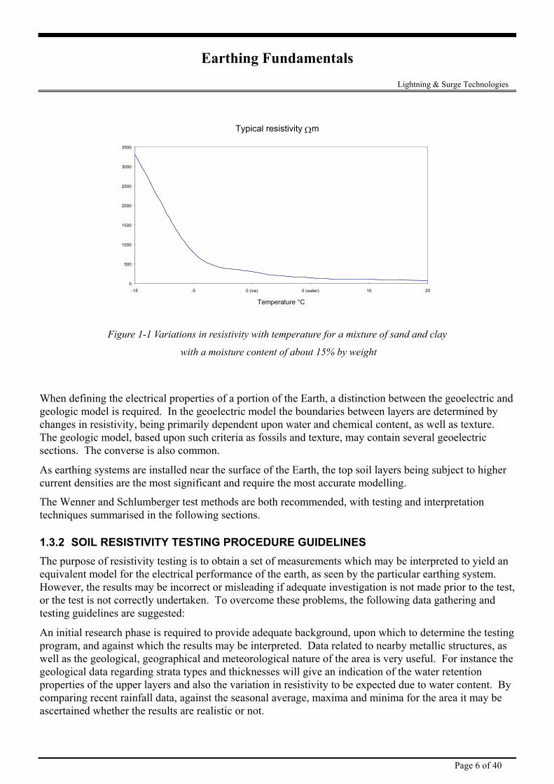
Figure 1-1 Variations in resistivity with temperature for a mixture of sand and clay
with a moisture content of about 15% by weight
When defining the electrical properties of a portion of the Earth, a distinction between the geoelectric and geologic model is required. In the geoelectric model the boundaries between layers are determined by changes in resistivity, being primarily dependent upon water and chemical content, as well as texture. The geologic model, based upon such criteria as fossils and texture, may contain several geoelectric sections. The converse is also common.
As earthing systems are installed near the surface of the Earth, the top soil layers being subject to higher current densities are the most significant and require the most accurate modelling.
The Wenner and Schlumberger test methods are both recommended, with testing and interpretation techniques summarised in the following sections.
1.3.2 SOIL RESISTIVITY TESTING PROCEDURE GUIDELINES The purpose of resistivity testing is to obtain a set of measurements which may be interpreted to yield an equivalent model for the electrical performance of the earth, as seen by the particular earthing system. However, the results may be incorrect or misleading if adequate investigation is not made prior to the test, or the test is not correctly undertaken. To overcome these problems, the following data gathering and testing guidelines are suggested:
An initial research phase is required to provide adequate background, upon which to determine the testing program, and against which the results may be interpreted. Data related to nearby metallic structures, as well as the geological, geographical and meteorological nature of the area is very useful. For instance the geological data regarding strata types and thicknesses will give an indication of the water retention properties of the upper layers and also the variation in resistivity to be expected due to water content. By comparing recent rainfall data, against the seasonal average, maxima and minima for the area it may be ascertained whether the results are realistic or not.
Page 6 of 40
Earthing Fundamentals Lightning & Surge Technologies A number of guidelines associated with the preparation and implementation of a testing program are summarised as follows:
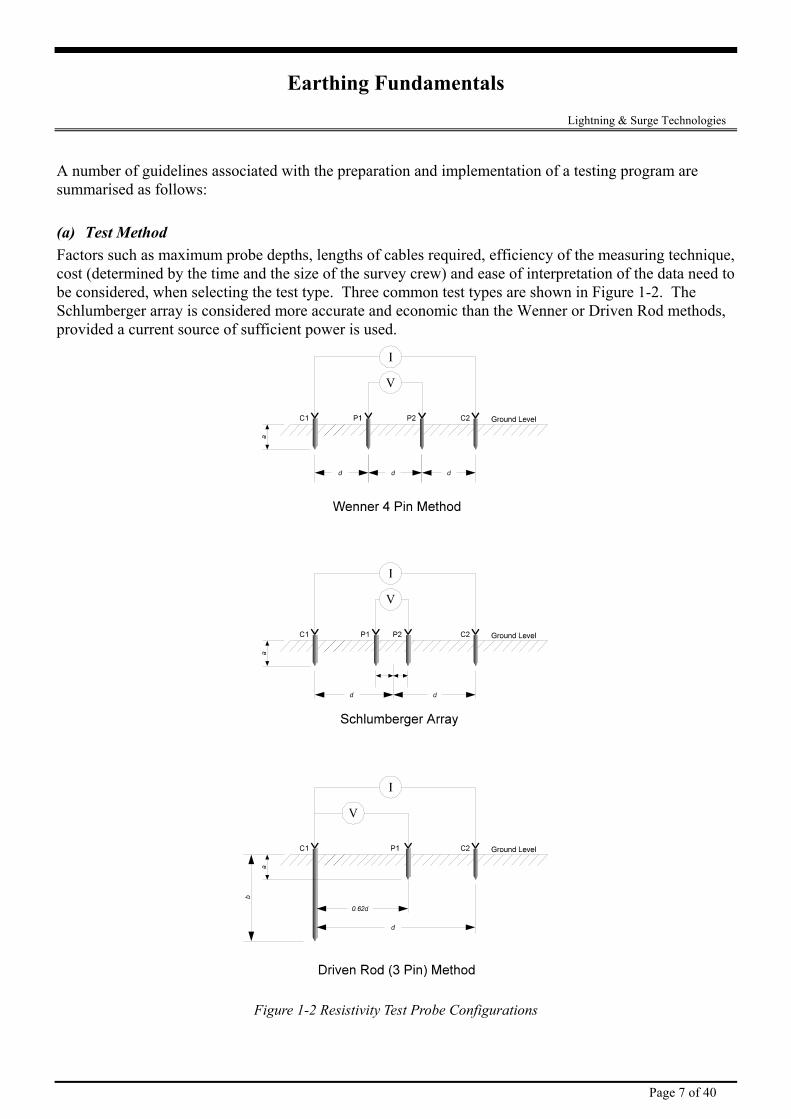
(a) Test Method Factors such as maximum probe depths, lengths of cables required, efficiency of the measuring technique, cost (determined by the time and the size of the survey crew) and ease of interpretation of the data need to be considered, when selecting the test type. Three common test types are shown in Figure 1-2. The Schlumberger array is considered more accurate and economic than the Wenner or Driven Rod methods, provided a current source of sufficient power is used.
Figure 1-2 Resistivity Test Probe Configurations
Page 7 of 40
Earthing Fundamentals Lightning & Surge Technologies In the Wenner method, all four electrodes are moved for each test with the spacing between each adjacent pair remaining the same. With the Schlumberger array the potential electrodes remain stationary while the current electrodes are moved for a series of measurements. In each method the depth penetration of the electrodes is less than 5% of the separation to ensure that the approximation of point sources, required by the simplified formulae, remains valid.
(b) Selection of Test Method Type Wenner Array The Wenner array is the least efficient from an operational perspective. It requires the longest cable layout, largest electrode spreads and for large spacings one person per electrode is necessary to complete the survey in a reasonable time. Also, because all four electrodes are moved after each reading the Wenner Array is most susceptible to lateral variation effects.
However the Wenner array is the most efficient in terms of the ratio of received voltage per unit of transmitted current.
Where unfavourable conditions such as very dry or frozen soil exist, considerable time may be spent trying to improve the contact resistance between the electrode and the soil.
Schlumberger Array Economy of manpower is gained with the Schlumberger array since the outer electrodes are moved four or five times for each move of the inner electrodes. The reduction in the number of electrode moves also reduces the effect of lateral variation on test results.
Considerable time saving can be achieved by using the reciprocity theorem with the Schlumberger array when contact resistance is a problem. Since contact resistance normally affects the current electrodes more than the potential electrodes, the inner fixed pair may be used as the current electrodes, a configuration called the ‘Inverse Schlumberger Array’. Use of the inverse Schlumberger array increases personal safety when a large current is injected. Heavier current cables may be needed if the current is of large magnitude. The inverse Schlumberger reduces the heavier cable lengths and time spent moving electrodes. The minimum spacing accessible is in the order of 10 m (for a 0.5m inner spacing), thereby, necessitating the use of the Wenner configuration for smaller spacings.
Lower voltage readings are obtained when using Schlumberger arrays. This may be a critical problem where the depth required to be tested is beyond the capability of the test equipment or the voltage readings are too small to be considered.
Driven Rod Method The driven rod method (or Three Pin or Fall-of-Potential Method) is normally suitable for use in circumstances such as transmission line structure earths, or areas of difficult terrain, because of: the shallow penetration that can be achieved in practical situations, the very localised measurement area, and the inaccuracies encountered in two layer soil conditions.
(c) Traverse Locations. Soil resistivity can vary significantly both with depth, and from one point to another at a site, and as such, a single soil resistivity measurement is usually not sufficient. To obtain a better picture of soil resistivity variations, it is advisable to conduct a detailed survey.
Page 8 of 40
Earthing Fundamentals Lightning & Surge Technologies
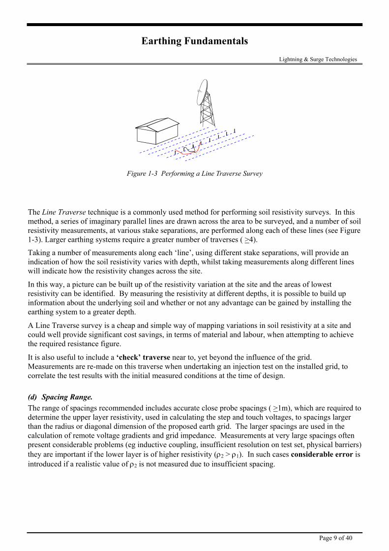
Figure 1-3 Performing a Line Traverse Survey
The Line Traverse technique is a commonly used method for performing soil resistivity surveys. In this method, a series of imaginary parallel lines are drawn across the area to be surveyed, and a number of soil resistivity measurements, at various stake separations, are performed along each of these lines (see Figure 1-3). Larger earthing systems require a greater number of traverses ( >4).
Taking a number of measurements along each ‘line’, using different stake separations, will provide an indication of how the soil resistivity varies with depth, whilst taking measurements along different lines will indicate how the resistivity changes across the site.
In this way, a picture can be built up of the resistivity variation at the site and the areas of lowest resistivity can be identified. By measuring the resistivity at different depths, it is possible to build up information about the underlying soil and whether or not any advantage can be gained by installing the earthing system to a greater depth.
A Line Traverse survey is a cheap and simple way of mapping variations in soil resistivity at a site and could well provide significant cost savings, in terms of material and labour, when attempting to achieve the required resistance figure.
It is also useful to include a ‘check’ traverse near to, yet beyond the influence of the grid. Measurements are re-made on this traverse when undertaking an injection test on the installed grid, to correlate the test results with the initial measured conditions at the time of design.
(d) Spacing Range. The range of spacings recommended includes accurate close probe spacings ( >1m), which are required to determine the upper layer resistivity, used in calculating the step and touch voltages, to spacings larger than the radius or diagonal dimension of the proposed earth grid. The larger spacings are used in the calculation of remote voltage gradients and grid impedance. Measurements at very large spacings often present considerable problems (eg inductive coupling, insufficient resolution on test set, physical barriers) they are important if the lower layer is of higher resistivity (ρ2 > ρ1). In such cases considerable error is introduced if a realistic value of ρ2 is not measured due to insufficient spacing.
Page 9 of 40
Earthing Fundamentals Lightning & Surge Technologies
(e) Practical Testing Recommendations. It has been found that special care is required when testing to:
• Eliminate mutual coupling or interference due to leads parallel to power lines. Cable reels with parallel axes for current injection and voltage measurements, and small cable separation for large spacings (>100m) can result in errors;
• Ensure the instrumentation and set up is adequate (ie equipment selection criteria, power levels, interference and filtering);
• Undertake operational checks for accuracy (ie, a field calibration check); • Reduce contact resistance (use salt water, stakes and/or the reverse Schlumberger); • Instruct staff to use finer test spacings in areas showing sharp changes (ie to identify the effect of
local inhomogeneities and give increased data for interpretation). Plot test results immediately during testing to identify such problem areas.
Page 10 of 40
Earthing Fundamentals Lightning & Surge Technologies
2. Interpretation and Modelling of Result
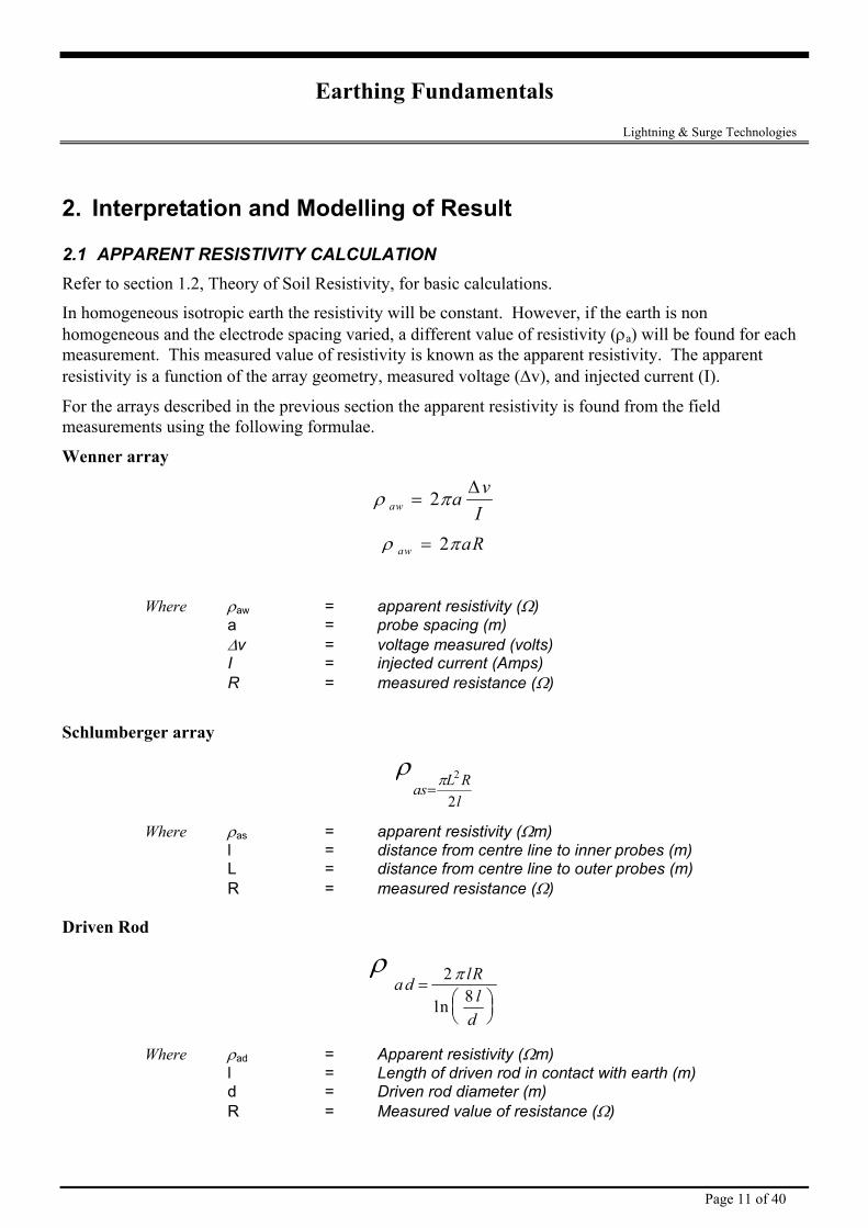
2.1 APPARENT RESISTIVITY CALCULATION Refer to section 1.2, Theory of Soil Resistivity, for basic calculations.
In homogeneous isotropic earth the resistivity will be constant. However, if the earth is non homogeneous and the electrode spacing varied, a different value of resistivity (ρa) will be found for each measurement. This measured value of resistivity is known as the apparent resistivity. The apparent resistivity is a function of the array geometry, measured voltage (∆v), and injected current (I).
For the arrays described in the previous section the apparent resistivity is found from the field measurements using the following formulae.
Wenner array
ρ πaw a vI
= 2 ∆
ρ πaw aR= 2
Where ρaw = apparent resistivity (Ω) a = probe spacing (m) ∆v = voltage measured (volts) I = injected current (Amps) R = measured resistance (Ω)
Schlumberger array
ρπas L R
l=
2
2
Where ρas = apparent resistivity (Ωm) l = distance from centre line to inner probes (m) L = distance from centre line to outer probes (m) R = measured resistance (Ω)
Driven Rod
ρ πa d lRl
d
=
28ln
Where ρad = Apparent resistivity (Ωm) l = Length of driven rod in contact with earth (m) d = Driven rod diameter (m) R = Measured value of resistance (Ω)
Page 11 of 40
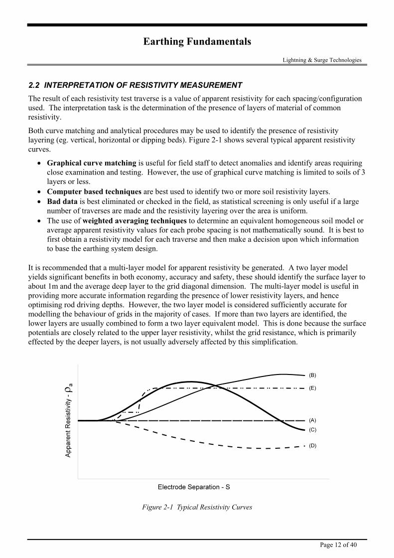
Earthing Fundamentals Lightning & Surge Technologies 2.2 INTERPRETATION OF RESISTIVITY MEASUREMENT The result of each resistivity test traverse is a value of apparent resistivity for each spacing/configuration used. The interpretation task is the determination of the presence of layers of material of common resistivity.
Both curve matching and analytical procedures may be used to identify the presence of resistivity layering (eg. vertical, horizontal or dipping beds). Figure 2-1 shows several typical apparent resistivity curves.
• Graphical curve matching is useful for field staff to detect anomalies and identify areas requiring close examination and testing. However, the use of graphical curve matching is limited to soils of 3 layers or less.
• Computer based techniques are best used to identify two or more soil resistivity layers. • Bad data is best eliminated or checked in the field, as statistical screening is only useful if a large
number of traverses are made and the resistivity layering over the area is uniform. • The use of weighted averaging techniques to determine an equivalent homogeneous soil model or
average apparent resistivity values for each probe spacing is not mathematically sound. It is best to first obtain a resistivity model for each traverse and then make a decision upon which information to base the earthing system design.
It is recommended that a multi-layer model for apparent resistivity be generated. A two layer model yields significant benefits in both economy, accuracy and safety, these should identify the surface layer to about 1m and the average deep layer to the grid diagonal dimension. The multi-layer model is useful in providing more accurate information regarding the presence of lower resistivity layers, and hence optimising rod driving depths. However, the two layer model is considered sufficiently accurate for modelling the behaviour of grids in the majority of cases. If more than two layers are identified, the lower layers are usually combined to form a two layer equivalent model. This is done because the surface potentials are closely related to the upper layer resistivity, whilst the grid resistance, which is primarily effected by the deeper layers, is not usually adversely affected by this simplification.
Figure 2-1 Typical Resistivity Curves
Page 12 of 40
Earthing Fundamentals Lightning & Surge Technologies
Curve (A) - Homogenous resistivity Curve (B) - Low resistivity layer overlaying higher resistivity layer Curve (C) - High resistivity layer between two low resistivity layers Curve (D) - High resistivity layer overlaying a lower resistivity layer Curve (E) - Low resistivity layer over high resistivity layer with a vertical discontinuity
(typically a fault line).
Page 13 of 40
Earthing Fundamentals Lightning & Surge Technologies
3. How to Design a Lightning Earth System Once the soil resistivity is known, the design of the Earthing system can be made to achieve the desired Earth resistance. Design parameters are given in the following sections.
3.1 TYPES OF EARTH ELECTRODES Earth electrodes must ideally penetrate into the moisture level below the ground level. They must also consist of a metal (or combination of metals) which do not corrode excessively for the period of time they are expected to serve. Because of its high conductivity and resistance to corrosion, copper is the most commonly used material for earth electrodes. Other popular materials are hot-galvanised steel, stainless steel, aluminium and lead.
Earth electrodes may be rods, plates, strips, solid section wire or mats.
Three types of copper rods are commonly available.
• Solid Copper
• Copper clad steel rod ( copper shrunk onto the core)
• Copper Bonded steel core (coper is molecularly bonded to nickel plated steel rod)
Solid copper rods not prone to corrosion, but are expensive and difficult to drive into hard ground without bending. A steel cored copper rod is used for this reason, however those rods that are simply clad are prone to the cladding tearing away from the core when driven in rocky ground, or when bent. This exposes the internal steel core to corrosion. The most cost effective solution is the copperbonded electrode which is a molecularly bonded steel cored copper ground rod.
3.2 COMMON EARTHING SYSTEMS The basic philosophy of any earth installation should be an attempt to maximise the surface area contact with the surrounding soil. Not only does such this help to lower the earth resistance of the grounding system, but it also greatly improves the surge impedance of the grounding system due to the large capacitive coupling which is achieved.
The benefits of a small amount of capacitive coupling into the surrounding earth is greatly enhanced when one considers that the fast rising edge associated with the lightning impulse has an inherent high fundamental frequency.
The actual layout of the earthing system will vary with the usages (lightning protection earth only, 50Hz power earth or combination) type of soil and space availability
Common lightning protection earths are shown in Figure 3-1- Methods of earthing.
A) Single earth rod, which is not generally acceptable other than in areas with a constantly high water table.
B) Earth rod with Copper subterranean tape. This is an improvement upon A, but not as effective as D) and E).
Page 14 of 40
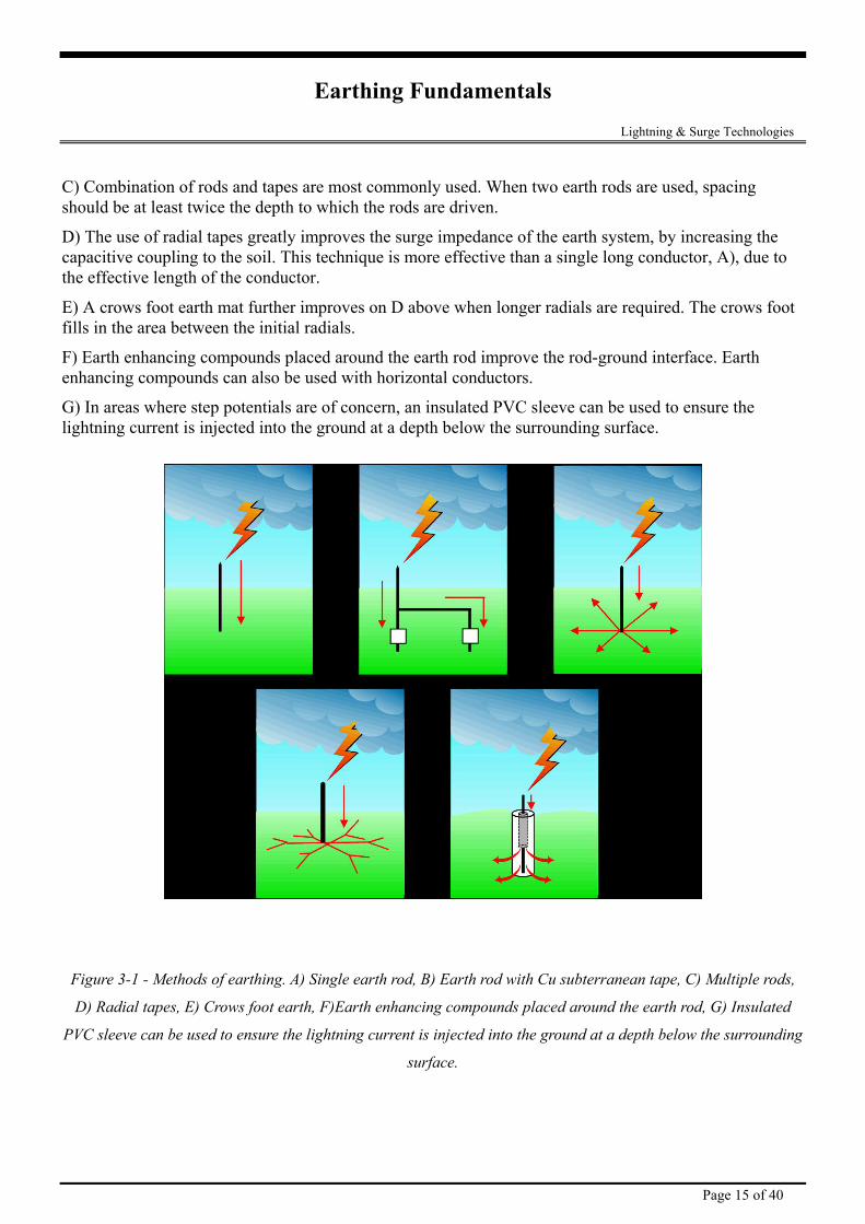
Earthing Fundamentals Lightning & Surge Technologies C) Combination of rods and tapes are most commonly used. When two earth rods are used, spacing should be at least twice the depth to which the rods are driven.
D) The use of radial tapes greatly improves the surge impedance of the earth system, by increasing the capacitive coupling to the soil. This technique is more effective than a single long conductor, A), due to the effective length of the conductor.
E) A crows foot earth mat further improves on D above when longer radials are required. The crows foot fills in the area between the initial radials.
F) Earth enhancing compounds placed around the earth rod improve the rod-ground interface. Earth enhancing compounds can also be used with horizontal conductors.
G) In areas where step potentials are of concern, an insulated PVC sleeve can be used to ensure the lightning current is injected into the ground at a depth below the surrounding surface.
Figure 3-1 - Methods of earthing. A) Single earth rod, B) Earth rod with Cu subterranean tape, C) Multiple rods,
D) Radial tapes, E) Crows foot earth, F)Earth enhancing compounds placed around the earth rod, G) Insulated
PVC sleeve can be used to ensure the lightning current is injected into the ground at a depth below the surrounding
surface.
Page 15 of 40
Earthing Fundamentals Lightning & Surge Technologies
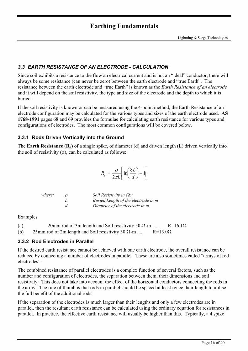
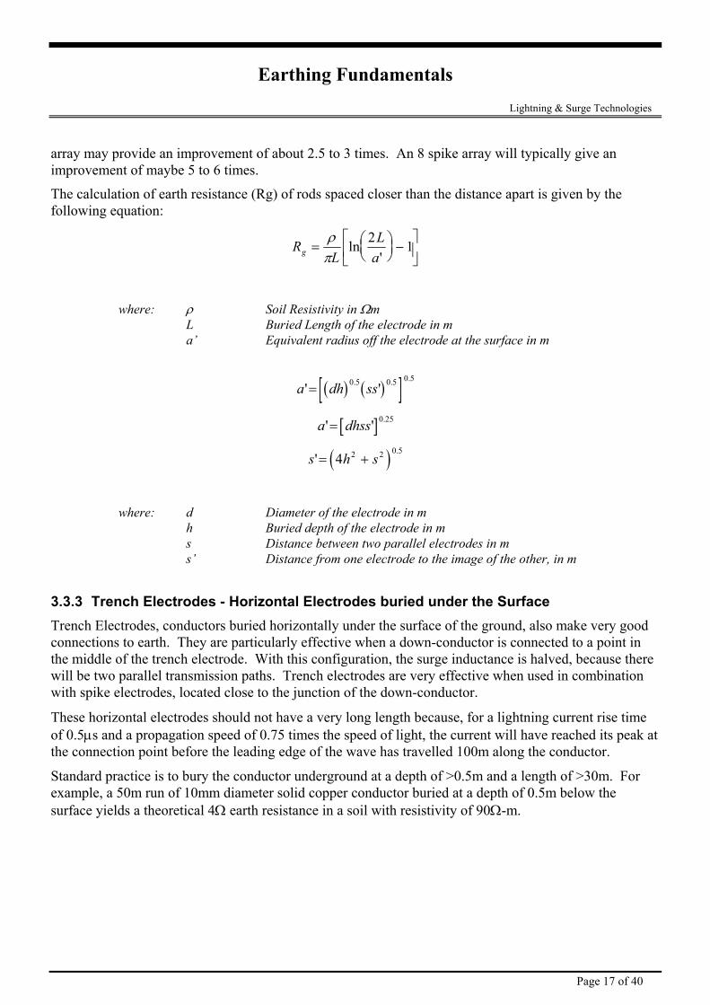
3.3 EARTH RESISTANCE OF AN ELECTRODE - CALCULATION Since soil exhibits a resistance to the flow an electrical current and is not an “ideal” conductor, there will always be some resistance (can never be zero) between the earth electrode and “true Earth”. The resistance between the earth electrode and “true Earth” is known as the Earth Resistance of an electrode
ctrode used. AS 1768-1991 pages 68 and 69 provides the formulae for calculating earth resistance for various types and
he Earth Resistance (Rg) of a single spike, of diameter (d) and driven length (L) driven vertically into the soil of resistivity (ρ), can be calculated as follows:
and it will depend on the soil resistivity, the type and size of the electrode and the depth to which it is buried.
If the soil resistivity is known or can be measured using the 4-point method, the Earth Resistance of an electrode configuration may be calculated for the various types and sizes of the earth ele
configurations of electrodes. The most common configurations will be covered below.
3.3.1 Rods Driven Vertically into the Ground T
RL
Ldg =
−
ρπ2
8 1
here: ρ Soil Resistivity in Ωm L Buried Length of the electrode in m d Diameter of the electrode in m
mp
and Soil resistivity 50 Ω-m ..... R=16.1Ω
If the desired earth resistance cannot be achieved with one earth electrode, the overall resistance can be f rod
s, the separation between them, their dimensions and soil resistivity. This does not take into account the effect of the horizontal conductors connecting the rods in
lise
ance can be calculated using the ordinary equation for resistances in parallel. In practice, the effective earth resistance will usually be higher than this. Typically, a 4 spike
ln
w
Exa les
(a) 20mm rod of 3m length (b) 25mm rod of 2m length and Soil resistivity 30 Ω-m ..... R=13.0Ω
3.3.2 Rod Electrodes in Parallel
reduced by connecting a number of electrodes in parallel. These are also sometimes called “arrays oelectrodes”.
The combined resistance of parallel electrodes is a complex function of several factors, such as the number and configuration of electrode
the array. The rule of thumb is that rods in parallel should be spaced at least twice their length to utithe full benefit of the additional rods.
If the separation of the electrodes is much larger than their lengths and only a few electrodes are in parallel, then the resultant earth resist
Page 16 of 40
Earthing Fundamentals Lightning & Surge Technologies array may provide an improveme es. An 8 spike array will typically give an improvement of maybe 5 to 6 times.
The calculation of earth resistance (Rg) of rods spaced closer than the distance apart is given by the following equation:
nt of about 2.5 to 3 tim
R L=
−
ρ ln 2 1 L ag
π '
Soil Resistivity in Ωm Buried Length of the electrode in m
where: ρ L a’ Equivalent radius off the electrode at the surface in m
( ) ( )[ ]a dh ss' '. .= 0 5 0 5 .0 5
[ ]a dhss' '= .0 25
( )s h s'.
= +4 2 2 0 5
h Buried depth of the electrode in m
e Surface
tion
ing current rise time of 0.5 s and a propagation speed of 0.75 times the speed of light, the current will have reached its peak at the connection point before the leading edge of the wave has travelled 100m along the conductor.
Standard practice is to bury the conductor underground at a depth of >0.5m and a length of >30m. For example, a 50m run of 10mm diameter solid copper conductor buried at a depth of 0.5m below the surface yields a theoretical 4Ω earth resistance in a soil with resistivity of 90Ω-m.
where: d Diameter of the electrode in m
s Distance between two parallel electrodes in m s’ Distance from one electrode to the image of the other, in m
3.3.3 Trench Electrodes - Horizontal Electrodes buried under thTrench Electrodes, conductors buried horizontally under the surface of the ground, also make very good connections to earth. They are particularly effective when a down-conductor is connected to a point in the middle of the trench electrode. With this configuration, the surge inductance is halved, because there will be two parallel transmission paths. Trench electrodes are very effective when used in combinawith spike electrodes, located close to the junction of the down-conductor.
These horizontal electrodes should not have a very long length because, for a lightnµ
Page 17 of 40
Earthing Fundamentals Lightning & Surge Technologies
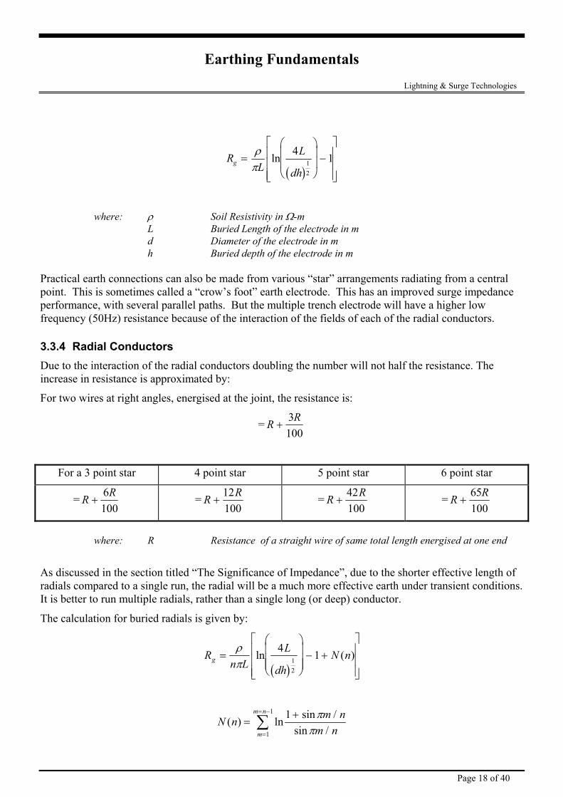
( )R
LL
dhg =
−
ρπ
ln 4 112
where: ρ Soil Resistivity in Ω-m L Buried Length of the electrode in m d Diameter of the electrode in m h Buried depth of the electrode in m
Practical earth connections can also be made from various “star” arrangements radiating from a central point. This is sometimes called a “crow’s foot” earth electrode. This has an improved surge impedance performance, with several parallel paths. But the multiple trench electrode will have a higher low frequency (50Hz) resistance because of the interaction of the fields of each of the radial conductors.
3.3.4 Radial Conductors Due to the interaction of the radial conductors doubling the number will not half the resistance. The increase in resistance is approximated by:
For two wires at right angles, energised at the joint, the resistance is:
= R R+
3100
For a 3 point star 4 point star 5 point star 6 point star
= R R+
6100
= R R+
12100
= R R+
42100
= R R+
65100
where: R Resistance of a straight wire of same total length energised at one end
As discussed in the section titled “The Significance of Impedance”, due to the shorter effective length of radials compared to a single run, the radial will be a much more effective earth under transient conditions. It is better to run multiple radials, rather than a single long (or deep) conductor.
The calculation for buried radials is given by:
( )R
n LL
dhN ng =
− +
ρπ
ln ( )4 112
N n m nm nm
m n
( ) ln sin /sin /
=+
=
= −
∑ 11
1 ππ
Page 18 of 40
Earthing Fundamentals Lightning & Surge Technologies
or
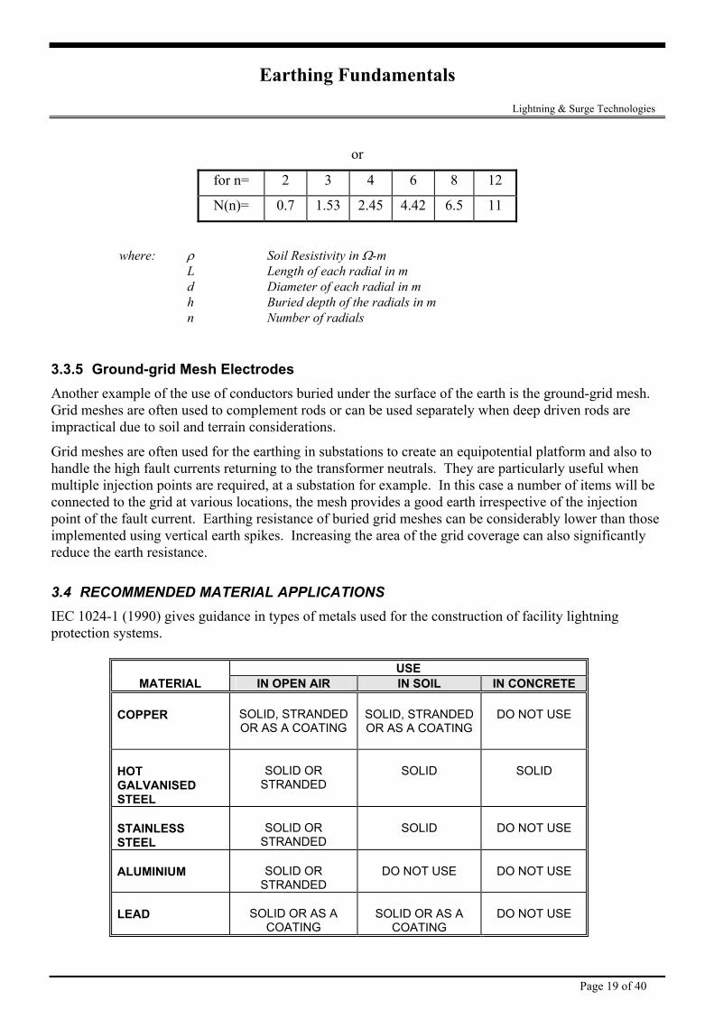
for n= 2 3 4 6 8 12
N(n)= 0.7 1.53 2.45 4.42 6.5 11
where: ρ Soil Resistivity in Ω-m L Length of each radial in m d Diameter of each radial in m h Buried depth of the radials in m n Number of radials
3.3.5 Ground-grid Mesh Electrodes Another example of the use of conductors buried under the surface of the earth is the ground-grid mesh. Grid meshes are often used to complement rods or can be used separately when deep driven rods are impractical due to soil and terrain considerations.
Grid meshes are often used for the earthing in substations to create an equipotential platform and also to handle the high fault currents returning to the transformer neutrals. They are particularly useful when multiple injection points are required, at a substation for example. In this case a number of items will be connected to the grid at various locations, the mesh provides a good earth irrespective of the injection point of the fault current. Earthing resistance of buried grid meshes can be considerably lower than those implemented using vertical earth spikes. Increasing the area of the grid coverage can also significantly reduce the earth resistance.
3.4 RECOMMENDED MATERIAL APPLICATIONS IEC 1024-1 (1990) gives guidance in types of metals used for the construction of facility lightning protection systems.
USE MATERIAL IN OPEN AIR IN SOIL IN CONCRETE
COPPER
SOLID, STRANDED OR AS A COATING
SOLID, STRANDED OR AS A COATING
DO NOT USE
HOT GALVANISED STEEL
SOLID OR
STRANDED
SOLID
SOLID
STAINLESS STEEL
SOLID OR
STRANDED
SOLID
DO NOT USE
ALUMINIUM
SOLID OR
STRANDED
DO NOT USE
DO NOT USE
LEAD
SOLID OR AS A
COATING
SOLID OR AS A
COATING
DO NOT USE
Page 19 of 40
Earthing Fundamentals Lightning & Surge Technologies
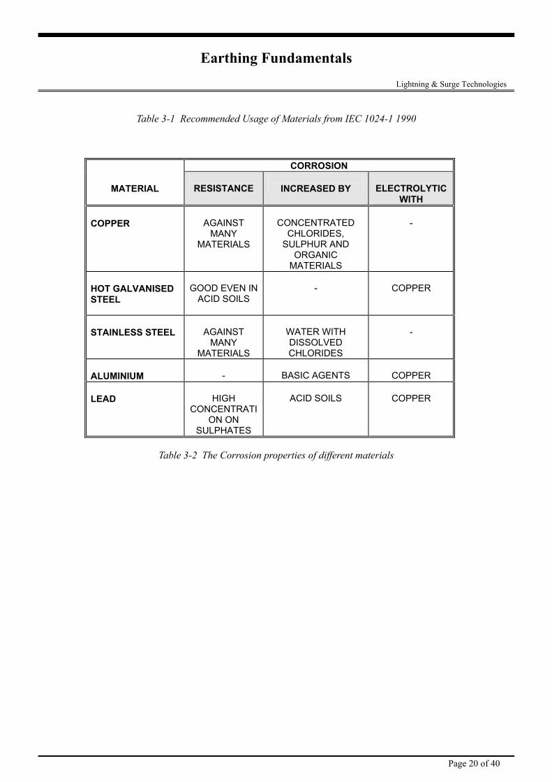
Table 3-1 Recommended Usage of Materials from IEC 1024-1 1990
CORROSION
MATERIAL
RESISTANCE
INCREASED BY
ELECTROLYTIC WITH
COPPER
AGAINST
MANY MATERIALS
CONCENTRATED
CHLORIDES, SULPHUR AND
ORGANIC MATERIALS
-
HOT GALVANISED STEEL
GOOD EVEN IN
ACID SOILS
-
COPPER
STAINLESS STEEL
AGAINST
MANY MATERIALS
WATER WITH DISSOLVED CHLORIDES
-
ALUMINIUM
-
BASIC AGENTS
COPPER
LEAD
HIGH
CONCENTRATION ON
SULPHATES
ACID SOILS
COPPER
Table 3-2 The Corrosion properties of different materials
Page 20 of 40
Earthing Fundamentals Lightning & Surge Technologies
4. Testing an Earthing System
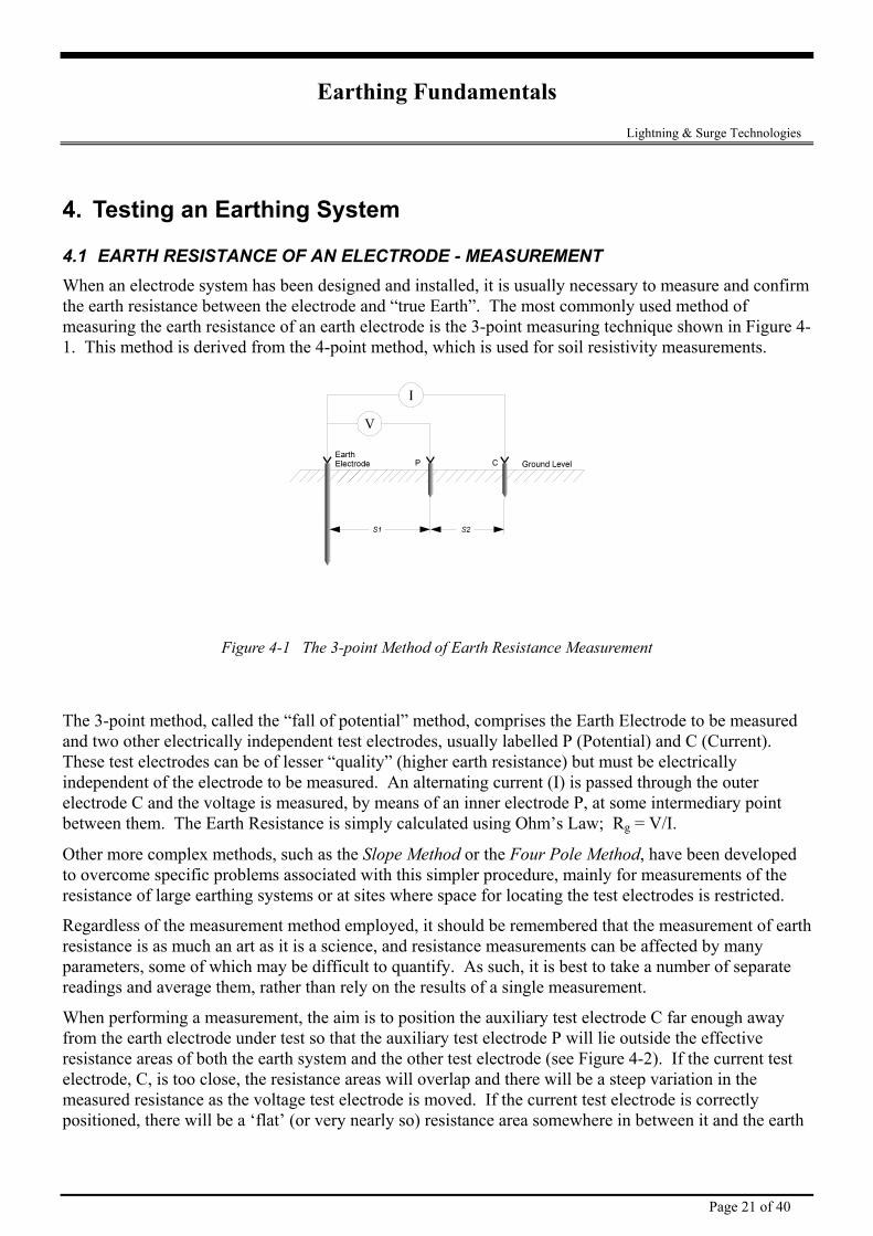
4.1 EARTH RESISTANCE OF AN ELECTRODE - MEASUREMENT When an electrode system has been designed and installed, it is usually necessary to measure and confirm the earth resistance between the electrode and “true Earth”. The most commonly used method of measuring the earth resistance of an earth electrode is the 3-point measuring technique shown in Figure 4-1. This method is derived from the 4-point method, which is used for soil resistivity measurements.
Figure 4-1 The 3-point Method of Earth Resistance Measurement
The 3-point method, called the “fall of potential” method, comprises the Earth Electrode to be measured and two other electrically independent test electrodes, usually labelled P (Potential) and C (Current). These test electrodes can be of lesser “quality” (higher earth resistance) but must be electrically independent of the electrode to be measured. An alternating current (I) is passed through the outer electrode C and the voltage is measured, by means of an inner electrode P, at some intermediary point between them. The Earth Resistance is simply calculated using Ohm’s Law; Rg = V/I.
Other more complex methods, such as the Slope Method or the Four Pole Method, have been developed to overcome specific problems associated with this simpler procedure, mainly for measurements of the resistance of large earthing systems or at sites where space for locating the test electrodes is restricted.
Regardless of the measurement method employed, it should be remembered that the measurement of earth resistance is as much an art as it is a science, and resistance measurements can be affected by many parameters, some of which may be difficult to quantify. As such, it is best to take a number of separate readings and average them, rather than rely on the results of a single measurement.
When performing a measurement, the aim is to position the auxiliary test electrode C far enough away from the earth electrode under test so that the auxiliary test electrode P will lie outside the effective resistance areas of both the earth system and the other test electrode (see Figure 4-2). If the current test electrode, C, is too close, the resistance areas will overlap and there will be a steep variation in the measured resistance as the voltage test electrode is moved. If the current test electrode is correctly positioned, there will be a ‘flat’ (or very nearly so) resistance area somewhere in between it and the earth
Page 21 of 40
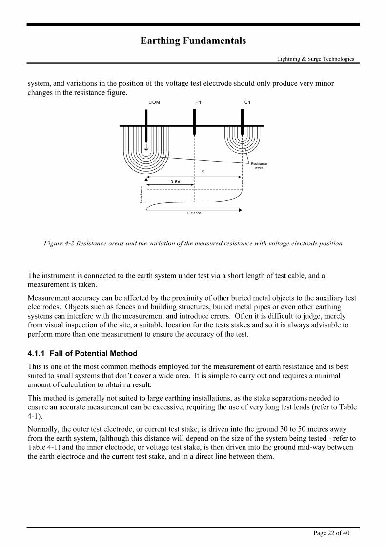
Earthing Fundamentals Lightning & Surge Technologies system, and variations in the position of the voltage test electrode should only produce very minor changes in the resistance figure.
Figure 4-2 Resistance areas and the variation of the measured resistance with voltage electrode position
The instrument is connected to the earth system under test via a short length of test cable, and a measurement is taken.
Measurement accuracy can be affected by the proximity of other buried metal objects to the auxiliary test electrodes. Objects such as fences and building structures, buried metal pipes or even other earthing systems can interfere with the measurement and introduce errors. Often it is difficult to judge, merely from visual inspection of the site, a suitable location for the tests stakes and so it is always advisable to perform more than one measurement to ensure the accuracy of the test.
4.1.1 Fall of Potential Method This is one of the most common methods employed for the measurement of earth resistance and is best suited to small systems that don’t cover a wide area. It is simple to carry out and requires a minimal amount of calculation to obtain a result.
This method is generally not suited to large earthing installations, as the stake separations needed to ensure an accurate measurement can be excessive, requiring the use of very long test leads (refer to Table 4-1).
Normally, the outer test electrode, or current test stake, is driven into the ground 30 to 50 metres away from the earth system, (although this distance will depend on the size of the system being tested - refer to Table 4-1) and the inner electrode, or voltage test stake, is then driven into the ground mid-way between the earth electrode and the current test stake, and in a direct line between them.
Page 22 of 40
Earthing Fundamentals Lightning & Surge Technologies
Maximum dimension across earth system
Distance from ‘electrical centre’ of earth system to voltage test stake
Minimum distance from ‘electrical centre’ of earth system to current test stake
1 15 30
2 20 40
5 30 60
10 43 85
20 60 120
50 100 200
100 140 280
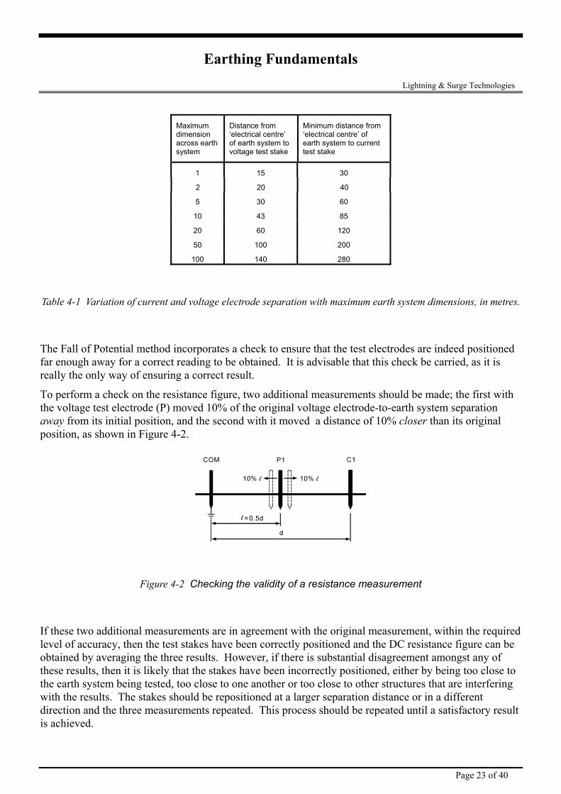
Table 4-1 Variation of current and voltage electrode separation with maximum earth system dimensions, in metres.
The Fall of Potential method incorporates a check to ensure that the test electrodes are indeed positioned far enough away for a correct reading to be obtained. It is advisable that this check be carried, as it is really the only way of ensuring a correct result.
To perform a check on the resistance figure, two additional measurements should be made; the first with the voltage test electrode (P) moved 10% of the original voltage electrode-to-earth system separation away from its initial position, and the second with it moved a distance of 10% closer than its original position, as shown in Figure 4-2.
Figure 4-2 Checking the validity of a resistance measurement
If these two additional measurements are in agreement with the original measurement, within the required level of accuracy, then the test stakes have been correctly positioned and the DC resistance figure can be obtained by averaging the three results. However, if there is substantial disagreement amongst any of these results, then it is likely that the stakes have been incorrectly positioned, either by being too close to the earth system being tested, too close to one another or too close to other structures that are interfering with the results. The stakes should be repositioned at a larger separation distance or in a different direction and the three measurements repeated. This process should be repeated until a satisfactory result is achieved.
Page 23 of 40
Earthing Fundamentals Lightning & Surge Technologies 4.1.2 The 62% Method The Fall of Potential method can be adapted slightly for use with medium sized earthing systems. This adaptation is often referred to as the 62% Method, as it involves positioning the inner test stake at 62% of the earth electrode-to-outer stake separation (recall that in the Fall-of-Potential method, this figure was 50%).
All the other requirements of test stake location - that they be in a straight line and be positioned away from other structures - remain valid. When using this method, it is also advisable to repeat the measurements with the inner test stake moved ±10% of the earth electrode-inner test stake separation distance, as before.
The main disadvantage with this method is that the theory on which it is based relies on the assumption that the underlying soil is homogeneous, which in practice is rarely the case. Thus, care should be taken in its use and a soil resistivity survey should always be carried out. Alternatively, one of the other methods should be employed.
4.1.3 Other Test Methods Many other methods exist for taking earth resistance measurements. Many of these methods have been designed in an attempt to alleviate the necessity for excessive electrode separations, when measuring large earth systems, or the requirement of having to know the electrical centre of the system.
Three such methods are briefly described below. Specific details are not given here, but instead the reader is referred to the relevant technical paper where these systems are described in detail.
(a) The Slope Method This method is suitable for use with large earthing systems, such as sub-station earths. It involves taking a number of resistance measurements at various earth system to voltage electrode separations and then plotting a curve of the resistance variation between the earth and the current. From this graph, and from data obtained from tables, it is possible to calculate the theoretical optimum location for the voltage electrode and thus, from the resistance curve, calculate the true resistance.
The additional measurement and calculation effort tends to relegate this system to use with only very large or complex earthing systems.
For full details of this method, refer to paper 62975, written by Dr G.F. Tagg, taken from the proceedings of IEE volume 117, No 11, Nov. 1970.
(b) The Star-Delta Method This technique is well suited to use with large systems in built up areas or on rocky terrain, where it may be difficult to find suitable locations for the test electrodes, particularly over long distances in a straight line.
Three test electrodes, set up at the corners of an equilateral triangle with the earth system in the middle, are used and measurements are made of the total resistance between adjacent electrodes, and also between each electrode and the earthing system.
Using these results, a number of calculations are performed and a result can be obtained for the resistance of the earth system.
Page 24 of 40
Earthing Fundamentals Lightning & Surge Technologies This method, developed by W. Hymers, is described in detail in Electrical Review, January 1975.
g the
ll of Potential method, except that a number of
The main draw back with the Four Potential method is that, like with the Fall of Potential method, it can require excessive electrode separation distances if the earthing system being measured is large.
(c) The Four Potential Method This technique, helps overcome some of the problems associated with the requirement for knowinelectrical centre of the earthing systems being tested.
This method is similar in set up to the standard Fameasurements are made with the voltage electrode at different positions and a set of equations are used tocalculate the theoretical resistance of the system.
Page 25 of 40
Earthing Fundamentals Lightning & Surge Technologies
5. The Significance of Impedance
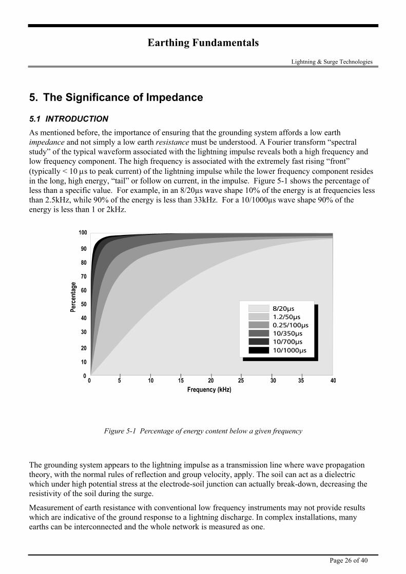
5.1 INTRODUCTION As mentioned before, the importance of ensuring that the grounding system affords a low earth impedance and not simply a low earth resistance must be understood. A Fourier transform “spectral study” of the typical waveform associated with the lightning impulse reveals both a high frequency and low frequency component. The high frequency is associated with the extremely fast rising “front” (typically < 10 µs to peak current) of the lightning impulse while the lower frequency component resides in the long, high energy, “tail” or follow on current, in the impulse. Figure 5-1 shows the percentage of less than a specific value. For example, in an 8/20µs wave shape 10% of the energy is at frequencies less than 2.5kHz, while 90% of the energy is less than 33kHz. For a 10/1000µs wave shape 90% of the energy is less than 1 or 2kHz.
Figure 5-1 Percentage of energy content below a given frequency
The grounding system appears to the lightning impulse as a transmission line where wave propagation theory, with the normal rules of reflection and group velocity, apply. The soil can act as a dielectric which under high potential stress at the electrode-soil junction can actually break-down, decreasing the resistivity of the soil during the surge.
Measurement of earth resistance with conventional low frequency instruments may not provide results which are indicative of the ground response to a lightning discharge. In complex installations, many earths can be interconnected and the whole network is measured as one.
Page 26 of 40
Earthing Fundamentals Lightning & Surge Technologies 5.2 THEORY Lightning first strokes have 1 to 10 µs impulse current rise times while higher dI/dts occurs with restrikes which occur in 75% of lightning discharges. These may have 0.2 µs rise time. In these circumstances, the local earth is subject to the full discharge current before the wavefront has travelled more than 60 metres. This assumes transmission at the speed of light (300 m/µs). The travel distance is less if inductance and capacitance of conductors is considered.
The effect of distant earths is substantially negated with these values of dI/dt. They have little effect in determining local voltage rise due to lead inductance and impedance effects. The following describes a measurement technique which allows differentiation between impedance and resistance effects.
5.2.1 Impulse Testing And The Transient Response The transient performance of an earthing system is simply a measure of the systems ability to discharge transient energy into the ground whilst minimising earth potential rise and ensuring that equipment and personnel are safe from any danger. It is one of the most important factors in determining the effectiveness of a lightning or surge protection system.
The two main elements of the earth system - the earth electrodes, which provide the electrical connection to the ground, and the wiring which bonds equipment to the earth electrodes - both impact on the transient performance. A poorly designed earth system, with a high impedance to ground can cause excessive earth potential rise, increasing the risk of damage to equipment and personnel.
5.2.2 Assessing the transient performance of an earthing system Any scheme which is employed to gauge the performance of the earth system under transient conditions must be capable of addressing the two major areas of importance:
• the peak voltage expected for a given current. • how the transient energy actually makes its way to ground. The simplest and most effective way of doing this is to simulate an actual transient impulse on the earth.
By injecting a current impulse of similar shape and form to that of a typical transient impulse into the earth, and then measuring how the earth system responds to this, the designer is able to gain very useful insight into how the system will perform in the event of a real transient.
This, in essence, is the principle of operation behind the Earth Systems Analyser.
As an example of the importance of testing the transient performance of an earthing system, consider the example below.
Page 27 of 40
Earthing Fundamentals Lightning & Surge Technologies
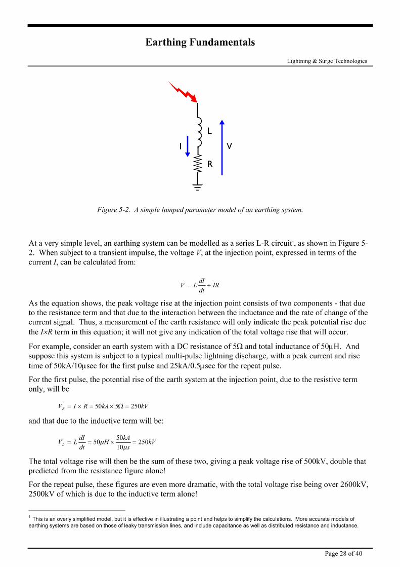
Figure 5-2. A simple lumped parameter model of an earthing system.
At a very simple level, an earthing system can be modelled as a series L-R circuit1, as shown in Figure 5-2. When subject to a transient impulse, the voltage V, at the injection point, expressed in terms of the current I, can be calculated from:
V L dIdt
IR= +
As the equation shows, the peak voltage rise at the injection point consists of two components - that due to the resistance term and that due to the interaction between the inductance and the rate of change of the current signal. Thus, a measurement of the earth resistance will only indicate the peak potential rise due the I×R term in this equation; it will not give any indication of the total voltage rise that will occur.
For example, consider an earth system with a DC resistance of 5Ω and total inductance of 50µH. And suppose this system is subject to a typical multi-pulse lightning discharge, with a peak current and rise time of 50kA/10µsec for the first pulse and 25kA/0.5µsec for the repeat pulse.
For the first pulse, the potential rise of the earth system at the injection point, due to the resistive term only, will be
V I R kA kVR = × = × =50 5 250Ω
and that due to the inductive term will be:
V L dIdt
H kAs
kVL = = × =50 5010
250µµ
The total voltage rise will then be the sum of these two, giving a peak voltage rise of 500kV, double that predicted from the resistance figure alone!
For the repeat pulse, these figures are even more dramatic, with the total voltage rise being over 2600kV, 2500kV of which is due to the inductive term alone!
1 This is an overly simplified model, but it is effective in illustrating a point and helps to simplify the calculations. More accurate models of earthing systems are based on those of leaky transmission lines, and include capacitance as well as distributed resistance and inductance.
Page 28 of 40
Earthing Fundamentals Lightning & Surge Technologies Clearly then, to assess the true performance of an earth network under transient conditions, some measurement of the effect of the inductive (and capacitive) elements needs to be made. Traditional earth resistance meters are not able to measure these effects, as they use a test signal with very low dI/dt levels (most resistance meters use a low frequency AC waveform as the test signal).
5.2.3 The Impulse Impedance As described earlier, the aim of the any earthing system that forms part of a surge protection installation is twofold - firstly, to ensure that the transient energy is diverted into ground via the safest and most direct route, and secondly, to ensure that in doing so, the resulting earth potential rise is not such that the risk of damage to equipment or injury to personnel is excessive.
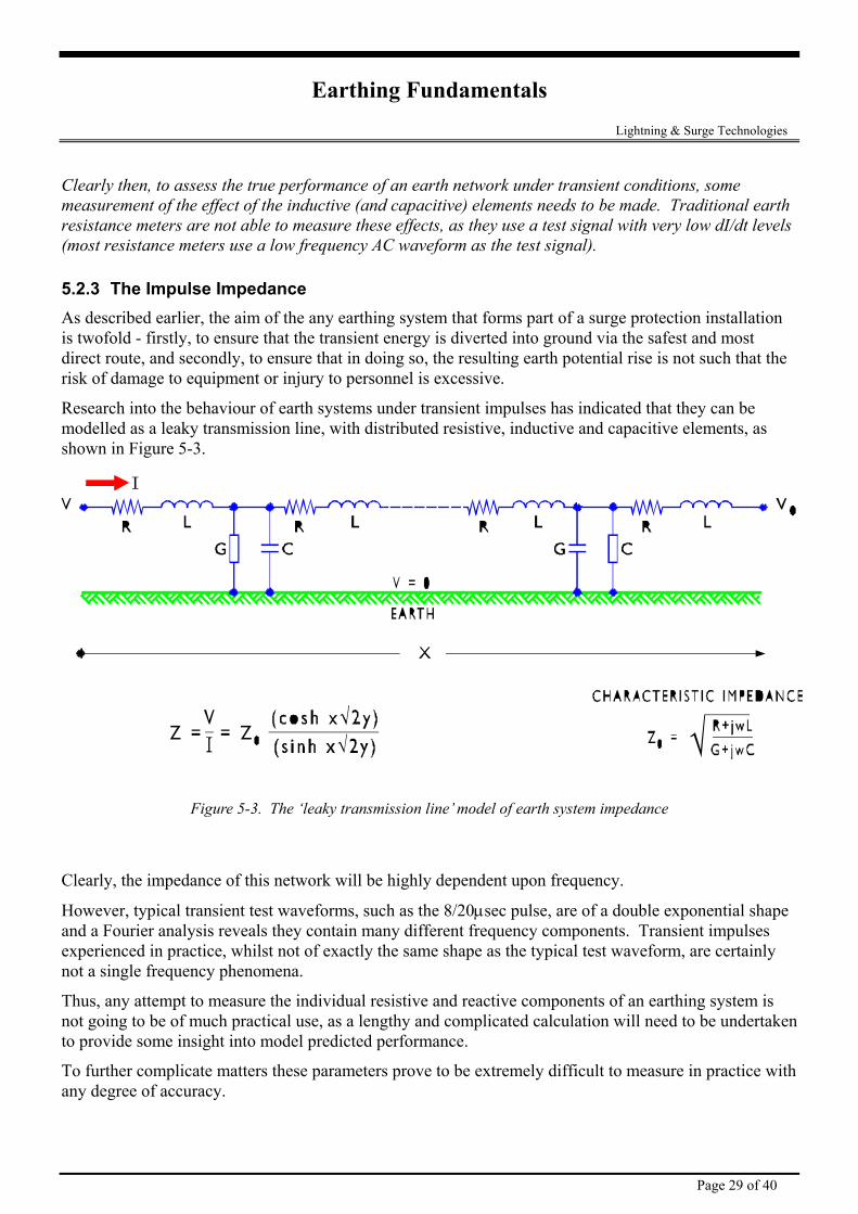
Research into the behaviour of earth systems under transient impulses has indicated that they can be modelled as a leaky transmission line, with distributed resistive, inductive and capacitive elements, as shown in Figure 5-3.
Figure 5-3. The ‘leaky transmission line’ model of earth system impedance
Clearly, the impedance of this network will be highly dependent upon frequency.
However, typical transient test waveforms, such as the 8/20µsec pulse, are of a double exponential shape and a Fourier analysis reveals they contain many different frequency components. Transient impulses experienced in practice, whilst not of exactly the same shape as the typical test waveform, are certainly not a single frequency phenomena.
Thus, any attempt to measure the individual resistive and reactive components of an earthing system is not going to be of much practical use, as a lengthy and complicated calculation will need to be undertaken to provide some insight into model predicted performance.
To further complicate matters these parameters prove to be extremely difficult to measure in practice with any degree of accuracy.
Page 29 of 40
Earthing Fundamentals Lightning & Surge Technologies A simpler model would avoid the necessity to know the actual values of the inductive, resistive and capacitive elements and instead simply provide a factor relating the peak voltage to the peak current, in a similar way that the resistance does in Ohm’s Law.
This introduces us to the concept of the Impulse Impedance, a figure which relates the peak current to the peak voltage.
5.2.4 Definition of the Impulse Impedance The impulse impedance, Zp, is defined as the peak voltage divided by the peak current. That is:
ZVIp
p
p
=
The impulse impedance (sometimes referred to as the surge impedance) of an earth system is a much more useful parameter, from the point of view of predicting system performance transient conditions, as it provides a direct relationship between the peak potential rise and the peak current.
The impulse impedance is also much simpler to measure. By injecting a current impulse into the earth system under test, it is a relatively straight forward exercise to measure the resulting peak of this current and of the voltage that it produces and hence calculate the impulse impedance. It is not necessary to measure the time difference between the voltage and current peaks, as it is the relationship between their magnitudes that we are really concerned with.
The use of an impulse as the test signal also provides a number of distinct practical advantages over other impedance measurement systems; namely the ability to perform selective impedance measurements on interconnected earth systems, and also the ability to trace how the test signal travels to ground, thus providing a means by which possibly catastrophic earth loops can be located before the damage occurs.
5.2.5 Interpreting Impulse Impedance Measurements Instruments for measuring the DC resistance of an earthing system have been around for many years and most people involved with earth system design and maintenance are familiar with their use, and their limitations.
With impulse impedance measurements, whilst the measurement technique is similar, there are an entirely new range of factors involved that can influence the result.
The sections that follow provide some recommendations regarding the interpretation of impulse impedance measurements, and should assist the user in getting more out of the information obtained from the Earth Systems Analyser.
5.2.6 Variations in the Impulse Impedance within an earthing system All earth systems involve interconnecting cables. With DC resistance measurements, the resistance of these cables (typically fractions of an ohm) are insignificant in comparison with the resistance of the earthing system. Thus, in an interconnected system, DC resistance measurements made at any point on the system will tend to agree with one another.
With impedance measurements, interconnecting cables, depending upon their shape, cross-sectional area, length and the number of bends, can present a significant impedance to the test signal. As such, it is possible to measure vastly different impedance results at different points around the system. It is
Page 30 of 40
Earthing Fundamentals Lightning & Surge Technologies advisable, therefore, to take measurements as close as possible to the point where a surge is likely to enter the system, such as at the base of a lightning protection down conductor, or at the earthing point for surge diversion equipment. This will give the best indication of the size of the impedance that a ‘real’ surge is likely to ‘see’.
5.2.7 Comparing Impulse Impedance and DC Resistance values Designers of earthing systems are often interested in how the impulse impedance figure compares with the DC resistance figure. The differences between these two figures can often be quite spectacular.
These differences can largely be attributed to the fact that most earthing systems involve more than one earthing electrode. The cables that connect each electrode to the system, some of which may be many metres in length, with numerous bends and joins, represent a significant addition to the overall impedance. In some cases, it can be so high as to remove the influence of large sections of the earth system from the impedance measurement.
The example of the transmission towers provided in the previous section is a case in point. DC resistance measurements made on a typical transmission tower that forms part of a long line of similar towers can be as low as 0.5Ω, due to the parallel combination of many towers. Yet an impulse impedance measurement on the same tower may produce a figure in the order of 40Ω!
Thus, care needs to be taken when comparing resistance and impedance figures. It is not always the case that a low impedance figure follows from a low resistance figure, or vice versa.
5.2.8 Selective Earth Testing in Interconnected Earth Systems To effectively test the earth resistance of an electrode in a multi-electrode system, it is necessary to isolate it from the rest of the system so as to eliminate the effects of parallel earth paths from the measurement of the local earth. Usually this is achieved by disconnecting the local electrode. However, disconnection can sometimes be difficult, particularly where access is limited or connecting bolts are badly corroded; it can often pose a significant danger as the conductors may be carrying large fault currents; and in some cases, such as when testing the earthing for transmission towers with an overhead guard wire, disconnection of the local earth can involve interruption to services as well as significant effort and cost. With lightning protection systems, it is only the earthing within a fairly small radius of the point of
ns.
injection (typically around 50 metres) that has any significant influence on the performance of the system. Because of the rapid rise times associated with lightning induced transients, parallel paths of more than a few tens of metres will present an impedance that will limit their ability to divert a significant portion of the total surge current to earth. Hence, any measurement of the lightning protection earth that includes the effect of more distant earths, such as is the case with DC resistancemeasurements, will not provide an accurate indication of its true performance under lightning conditio
This gives rise to the important “rule of thumb”, “the 50 meter rule”. It is the first 50 meters of earthing that will have the greatest effect under transient conditions.
For example to achieve a desired resistance target, it may be required to bury a straight length of 150 r,
meters of copper cable. This will achieve the resistance target as measured by a simple resistance meteand for 50Hz power faults. It would not be an effect earth for dissipation of a lightning transient due to its
Page 31 of 40
Earthing Fundamentals Lightning & Surge Technologies length. A more effective method would be to use 8 radials in a star pattern, each approx 19 meters long. Although this will have a slightly higher resistance (refer section 3.3.4), under lightning impulse conditions it will present a much lower impedance and lower the voltage rise at the injection point
By utilising an impulse as the test signal, as implemented with the Earth Systems Analyser, it is poss
.
ible
hs from any
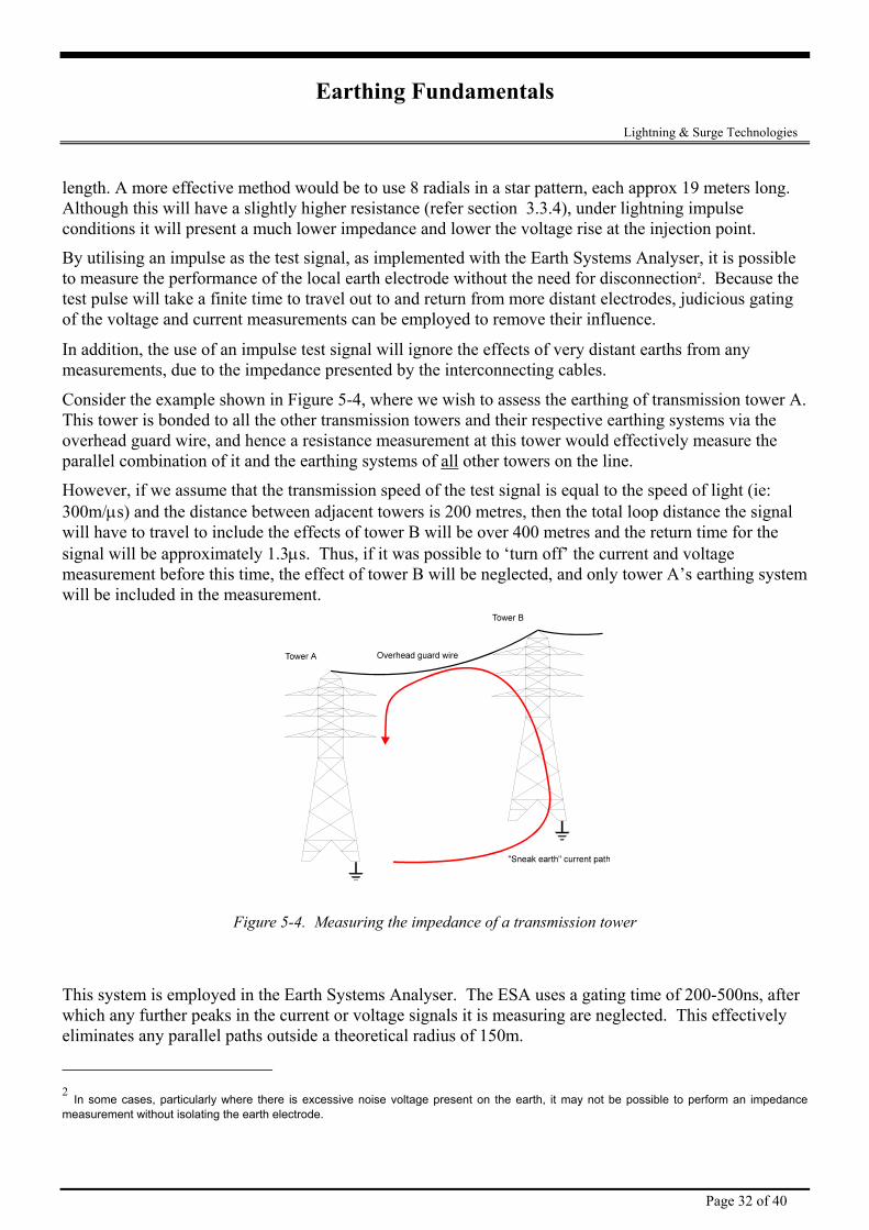
g of transmission tower A.
to measure the performance of the local earth electrode without the need for disconnection2. Because the test pulse will take a finite time to travel out to and return from more distant electrodes, judicious gating of the voltage and current measurements can be employed to remove their influence.
In addition, the use of an impulse test signal will ignore the effects of very distant eartmeasurements, due to the impedance presented by the interconnecting cables.
Consider the example shown in Figure 5-4, where we wish to assess the earthinThis tower is bonded to all the other transmission towers and their respective earthing systems via the overhead guard wire, and hence a resistance measurement at this tower would effectively measure the parallel combination of it and the earthing systems of all other towers on the line.
However, if we assume that the transmission speed of the test signal is equal to the speed of light (ie: al
g system
300m/µs) and the distance between adjacent towers is 200 metres, then the total loop distance the signwill have to travel to include the effects of tower B will be over 400 metres and the return time for the signal will be approximately 1.3µs. Thus, if it was possible to ‘turn off’ the current and voltage measurement before this time, the effect of tower B will be neglected, and only tower A’s earthinwill be included in the measurement.
Figure 5-4. Measuring the impedance of a transmission tower
This system is employed in the Earth Systems Analyser. The ESA uses a gating time of 200-500ns, after which any further peaks in the current or voltage signals it is measuring are neglected. This effectively eliminates any parallel paths outside a theoretical radius of 150m.
2 In some cases, particularly where there is excessive noise voltage present on the earth, it may not be possible to perform an impedance measurement without isolating the earth electrode.
Page 32 of 40
Earthing Fundamentals Lightning & Surge Technologies However, given that the transmission speed of the test current in the soil is actually considerably less than the speed of light and that the impedance of interconnecting cables of this length would be many tens of ohms, in practice, the radius of exclusion for parallel earths is often much smaller than this and typically
modern techniques developed by Erico Lightning Technologies can trace and cure lightning induced equipment damage.
gies offers a consultancy service with the Earth System Analyser together with
world ranging from Botswana to USA, from Europe to
wer
is in the order of 40-50 metres.
5.3 CONCLUSIONS These case examples show how
Erico Lightning Technolothe professional experience of senior lightning protection engineers. This experience covers many hundred investigations of damage in areas of theChina and all S.E. Asian countries. This experience is available to correct problems at individual stations or, confirm generic solutions when repetitive designs such as cell radio sites are designed. In the poutility field, tower footing impedances can also be recorded without removal of either earth conductors orthe overhead earth wire. This service is capable of providing corrective solutions to virtually any site where lightning is causing damage to electrical equipment.
Page 33 of 40
Earthing Fundamentals Lightning & Surge Technologies
6. Practical Earth System Analysis The Impulse Test mode introduces a new diagnostic tool in the area of earth system testing and analysis. Using this mode, the designer is now able to gain a much better understanding of how the earth system behaves under transient conditions.
There are two main factors to consider when assessing the performance of an earthing system under transient conditions:
• the impulse impedance - this will dictate the peak voltage rise for a given peak current; • the path that the current follows to ground - the aim here is to ensure that the majority, if not all, of
the transient current travels to ground via a preferred path, which will not cause damage to equipment or be a risk to the safety of personnel.
The Earth Systems Analyser provides the facility to test both these areas.
6.1 APPLICATION EXAMPLES
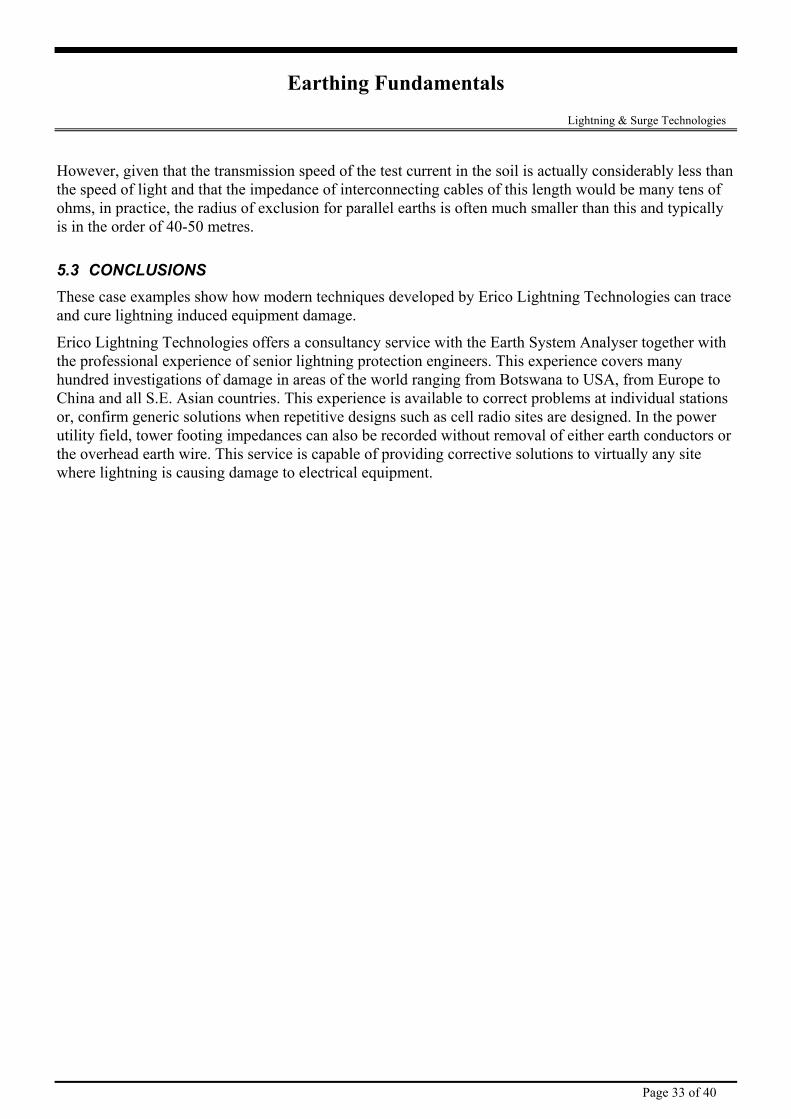
6.1.1 Satellite Ground Station
Figure 6-1
This station comprised a central building housing transmit/receive/MUX equipment, with feeder cables to seven outlying 30 metre diameter parabolic antennas. Each antenna was fitted with independent lightning protection air terminals, downconductors and a local earth.
The local earth was found to be impossible to measure with conventional instrumentation under normal service conditions. Waveguides, coaxial cables, power and control conductors all link the earth at each parabolic antenna with that of the transmission hall and to the grounding of the electric power supply.
The presence of a corroded or faulty earth at the antenna significantly increases the magnitude of lightning current flowing into the transmission hall. Therefore, knowledge of the state of the antenna earth is a critical protection parameter.
The earth system analyser allowed the impedance of the local earth to be measured. It also allows a proportional measurement to provide the ratio of pulse current passing into the local earth compared with that flowing to the transmitter hall.
Page 34 of 40
Earthing Fundamentals Lightning & Surge Technologies This data provided the basis of need to repair and replace conductors or, to extend each individual antenna earth system.
6.1.2 Marine Communications Centre
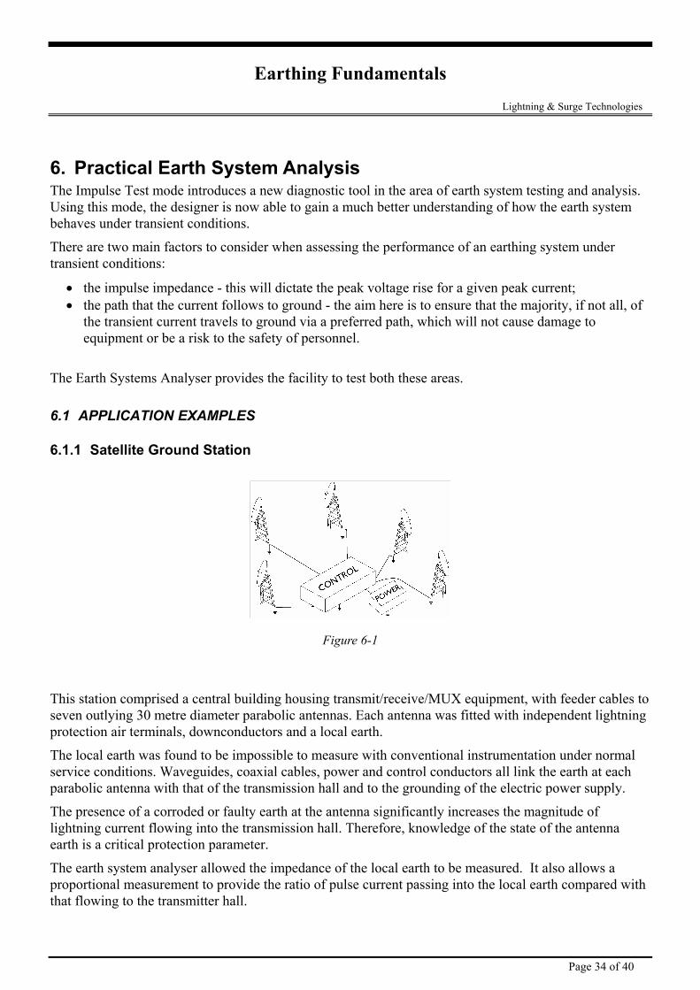
Figure 6-2
This centre comprised a number of high power HF transmitters plus VHF ship to shore installations. External to the main building are extensive arrays of HF antennas each with local grounding. Adjacent is a 30 metre mast supporting a VHF yagi antenna.
The VHF antenna mast was struck by lightning causing considerable damage with evidence of flashover in the operating consoles. Complete electronic modules were destroyed beyond repair.
Measurements made at the base of the mast indicated 2 ohms on a conventional meter and over 50 ohms on the Earth System Analyser. In this case it was possible to disconnect the catenary feeder to the VHF antenna. Repeat measurements revealed the mast grounding using the conventional meter had risen to approx. 45 ohms. The earth analyser reading remained essentially the same.
This was a case where the catenary feeder cable was bringing the main station earth to the mast and swamping the true ground resistance with that of the station. The lightning found a high resistance earth at the mast and a more conducive path to ground by flowing through the transmitter building.
Later, the Analyser was used on continuous pulse and the method of lightning entry to the station and consoles was traced. This allowed rearrangement of cable and earth routing and, appropriate bonding to ensure no further lightning entry to the internal consoles.
Page 35 of 40
Earthing Fundamentals Lightning & Surge Technologies
6.1.3 PABX lightning induced damage
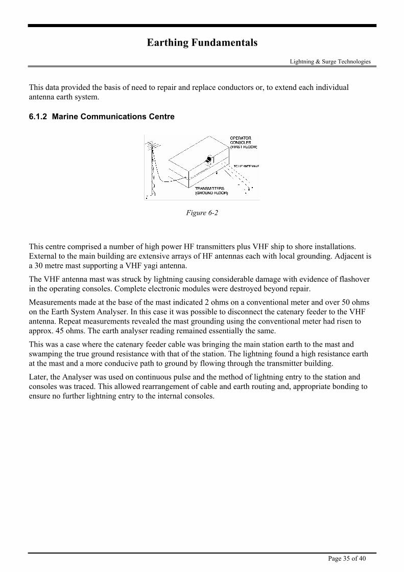
Figure 6-3
A PABX located on the first floor of a building had circuit card failures other than those for power or line interface. The Earth Analyser was connected to the earth electrode at ground level and pulse current measured. Approx. 50% went to the earth stake and out along the buried cable guard wire. The balance was traced to the earth lead riser to the MDF adjacent to the PABX.
Further tracing with the Analyser on automatic showed the pulse entered the PABX on one set of cables and left on another. The latter crossed the room to a Modem. The currents ceased when the modem power plug was removed.
Appropriate recabling and bonding removed any further risk of damage.
6.1.4 Cellular radio site
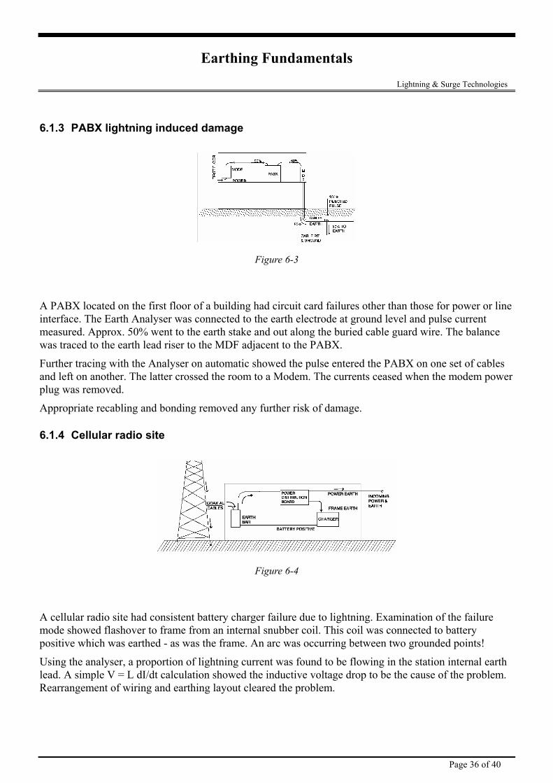
Figure 6-4
A cellular radio site had consistent battery charger failure due to lightning. Examination of the failure mode showed flashover to frame from an internal snubber coil. This coil was connected to battery positive which was earthed - as was the frame. An arc was occurring between two grounded points!
Using the analyser, a proportion of lightning current was found to be flowing in the station internal earth lead. A simple V = L dI/dt calculation showed the inductive voltage drop to be the cause of the problem. Rearrangement of wiring and earthing layout cleared the problem.
Page 36 of 40
Earthing Fundamentals Lightning & Surge Technologies
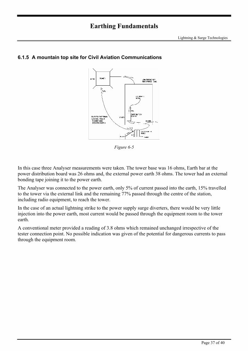
6.1.5 A mountain top site for Civil Aviation Communications
Figure 6-5
In this case three Analyser measurements were taken. The tower base was 16 ohms, Earth bar at the power distribution board was 26 ohms and, the external power earth 38 ohms. The tower had an external bonding tape joining it to the power earth.
The Analyser was connected to the power earth, only 5% of current passed into the earth, 15% travelled to the tower via the external link and the remaining 77% passed through the centre of the station, including radio equipment, to reach the tower.
In the case of an actual lightning strike to the power supply surge diverters, there would be very little injection into the power earth, most current would be passed through the equipment room to the tower earth.
A conventional meter provided a reading of 3.8 ohms which remained unchanged irrespective of the tester connection point. No possible indication was given of the potential for dangerous currents to pass through the equipment room.
Page 37 of 40
Earthing Fundamentals Lightning & Surge Technologies
7. Improving an Earthing System Whether improving an existing system or ensuring that a new system will meet it’s design specifications, the following points can be used to improve the final system performance.
7.1 FACTORS TO CONSIDER Low soil resistivity is to some extent tied to an electrolytic mechanism with such characteristics as - chemicals composition, soil ionisation, homogenous grain size and even distribution, playing a large determinant due to the effect on the retention of soil moisture and packing density in contact with the electrode.
Temp. C Typical resistivity Ωm 20 10
0 (water) 0 (ice)
-5 -15
72 99
138 300 790
3300
Table 7-1 - Variations in resistivity with temperature for a mixture of sand and clay
with a moisture content of about 15% by weight
Obtaining a satisfactory earth resistance has always been a problem in areas of poor soil conductivity. Most National and International Lightning Protection codes require an earth resistance of 10 ohms or less to be provided for a lightning protection installation.
The laying of copper grids, tapes and rods alone may not always provide the desired result. Even if copper materials are used and the specified resistance level is achieved, seasonal fluctuations in soil moisture can cause variations in the resistance level. In dry periods it is possible for the earth resistance to rise above the as installed level. This variation is earth resistance can effect the integrity of the entire lightning protection system.
If suitable electrical resistance cannot be simply and economically attained by the installation of a standard earth grid, an application of earth enhancing compound will assist. Such compounds consists of chemical solutions of good electrical conductivity which, when mixed with water and poured onto the earthing grid and surrounding soil become a gelatinous mass, forming an integral part of the overall earthing system. Field tests have shown dramatic improvement in earth resistance when such compounds are added to high resistivity soils such as shale or silica.
Erico supplies two such compound; Earth Gel and GEM. Earth Gel comes in kit form and comprises of two 5kg parts consisting of a copper solution in one and a complex mixture of chemicals which assists in the “gelling” stage, in the other. Of particular advantage with this compound is that it will not wash or leach away like many other resistance improving mixtures. This obviates the need to redose the area with time.
Page 38 of 40
Earthing Fundamentals Lightning & Surge Technologies 7.2 EXAMPLES OF ACHIEVING SUITABLE EARTHING INSTALLATIONS USING CHEMICAL ADDITIVES
7.2.1 Example 1 First obtain a rough determinant of the earth resistivity by driving a test earth rod. By referring to previous tables an estimate of the likely number of rods which will be required can be obtained. It may only be necessary to drive in one copper (or more generally a steel core/copper clad) rod. Dig a hole 500mm deep x 200mm diameter around it and apply approximately 2kg of each part of a kit of compound to fill the cavity. Allow 30 minutes for the compound to gel, and measure the resistance.
If the resistance is not low enough, dig a trench 500mm deep x 200mm wide and approximately 5 metres long. Lay a length of copper tape (approximately 3 inch wide x 0.1in thick) into this trench, again applying approximately 3kg of each part of a kit of compound. Allow time for the compound to gel and remeasure. If necessary, repeat the procedure laying tapes radially outwards from the main electrode until a satisfactory resistance is obtained. The earth tapes should be replaced as far apart as possible from one another and securely connected to the main earth rod.
7.2.2 Example 2 In rocky/shaley ground the best results are obtained by digging a trench approximately 500mm deep and 200mm wide and laying the earthing material in the bottom and covering it with approx 100mm of fine soil or sand. Solution 1 is then poured on and when it has been absorbed Solution 2 is added in a similar manner. The entire trench is then backfilled.
7.2.3 Example 3 If a good resistance is required in sold rock or heavy shale, one approach is to drilled a hole approximately 75mm wide and 250mm deep and insert the copper rod. Then mix solution 1 and 2 together and pour the mixture down the hole. In effect this will provide a conductive medium of 250mm x 75mm as an earth. If a suitable resistance is not obtained repeat the above procedure using multiple earth rods and bond together using copper tape laid in a trench.
7.2.4 Example 4 With existing earth mats expose as much of the grid as possible. Apply Solution 1, wait until it is absorbed, apply solution 2 and then backfill the entire grid.
7.3 NOTES ON THE APPLICATION OF CHEMICAL COMPOUNDS Before applying the compound, saturate the ground with water to assist with the distribution of the chemicals.
It must be stressed that every application is different and therefore results will differ accordingly. Generally speaking, one kit will be sufficient to produce a satisfactory earth resistance over a 5 metre length of earth tape in the worse soil conditions. In better soil conditions, one such kit will generally be adequate to cover 5 metres of earth tape.
Page 39 of 40
Earthing Fundamentals Lightning & Surge Technologies
Page 40 of 40
7.3.1 Measures For Reducing The Impulse Impedance Having measured the impulse impedance of your earthing system, the next question becomes “How do I go about improving it?”.
Whilst the actual percentage improvement gained will be highly dependent upon local conditions, the following measures can be used to reduce the impulse impedance of earthing systems.
• The use of flat tape rather than circular conductors. For a given cross-section of conductor, this increases the surface area in contact with the ground, and hence increases capacitive coupling and reduces the overall contact resistance. It also reduces the high frequency resistance due to skin effects. Flat tape also tends to have a lower inductance per metre than a circular conductor of equivalent cross-sectional area.
• The use of short-length radial conductors bonded at the injection point, rather than a single long length conductor. This produces the effect of having a number of conductors in parallel.
• Terminating radial conductors with vertical electrodes. This measure is more effective in low to medium soil resistivity.
• Using large bending radii when changing the direction of horizontal conductors. Sharp bends tend to increase the inductance.
• The use of earth enhancing compounds to improve the soil resistivity in the proximity of the conductors. Lowering the soil resistivity reduces the resistive component of the impedance and hence improves the total impedance.
7.4 WHAT TO DO IN EXTREME CASES ? In exceptional cases, the question may arise as to whether any further soil improvement is possible, or what to do on top of a granite mountain top. In such circumstances it is critical that expert assistance be sort. It is important that personnel safety is assured by either minimising access to areas where large step potentials may exist, or the extensive use of grounding mats etc.
For equipment protection the consultant should change the emphasis from seeking to lower the earth resistance of the grounding system to rather trying to lower the earth impedance adopting all such measures as may be available to increase the capacitive coupling with the surrounding ground. One such method involves bonding the local earth into the reinforcing bars used in concrete slabs such as in adjacent buildings or even car parks.
In all such cases special attention must be paid to the adequate bonding of all equipment, and ensuring that all earth loops are eliminated.