1 introduction ijser · 2.2 types of tools. single flute end mill cutters are classified according...
TRANSCRIPT
International Journal of Scientific & Engineering Research, Volume 6, Issue 5, May-2015 1263 ISSN 2229-5518
IJSER © 2015 http://www.ijser.org
Types, geometry and measurement of tool parameters of single flute end mill cutters
Ventsislav Dimitrov
Abstract— This article is designed as a set of three interconnected elements. Here are presented the purpose and the general classification of single flute end mill cutters, construction and geometry of tools, just like schemes solutions for the measurement of the constructional elements and geometric parameters through universal control device – CGCT. 01.
Index Terms— cutting tools, single flute end mill cutters, high-speed milling (HSM), measuring and control devices
—————————— ——————————
1 INTRODUCTION ingle flute end mill cutters are cutting tools purpose for high-speed (HSM) and high-precision machining (HPM) of aluminium sheets, profiles, composite panels, high
presssure laminate (HPL) panels, wood, polycarbonate, acrylic, brass, some light alloys (nickel, titanium) and bimetallic composition [5],[6].
Single flute end mill cutters operate under conditions of intense friction, adhesion and diffusion processes.
High-speed machining by chip removal with single flute end mill cutters ensures high efficiency of processes in combination with precision and the quality of the products. In many cases, the use of technology eliminates the need to apply additional finishing machining operations such as grinding and polishing.
The main advantage of the tools is an option set in the structural geometry of their fast start feeding the chip in the body clearance channel of the tool without jamming, accumulation or secondary deformation due to relatively more width compared with that for two, three or four channel tools. While maintaining a constant volume of the grooves, their length reduced which greatly increases their mechanical strength and increases the stability and vibration resistance of the tool. The core of the cutter has a maximum diameter in a relatively long section of body and suffers higher bending moments. Consequently single flute end mill cutters operate at higher thicknesses of cutting metal layers [1], [4], [6], [12].
2 PART I – GENERAL CLASSIFICATION AND TYPES OF TOOLS
2.1 Introduction in part I The cutting part, regardless of the type of the tool allows, it
to perform fine primary cut into the material of the workpiece until the on the given cutting depth, forming a cylindrical surface, characterized in minimum deflections from the form.
The trend is to manufacturing of tools with lightweight and well balanced structure protecting aerostatic spindle bearings and rise in cutting speeds intensive small moments of inertia.
2.2 Types of tools
Single flute end mill cutters are classified according to a set of structural, geometric and operational criteria are, forming their area of application [9], [10], [11]:
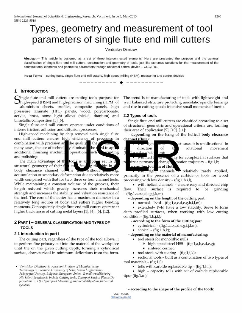
- depending on the hang of the helical body clearance channel (flute):
• with right hand - in most cases it is unidirectional in the direction of the rotational movement (fig.1,а,c,d,e,g,h,i,j,k,l,m);
• with left hand – mainly for complex flat surfaces that require a permanent change in motion trajectory – fig.1,b;
- according to form of flute: • with right channels – relatively rarely applied,
primarily in the presence of a carbide or tools for wood processing with low density – (fig.1,h,i,l),
• with helical channels – ensure easy and directed chip flow. Their surface is required to be grinding – (fig.1,а,b,c,d,e,g,j,k,m)
- depending on the length of the cutting part: • normal – l<4d – (fig.1,а,c,d,e,g,h,i,l,m); • extended– l>4d have a low stability. Serve to form
deep profiled surfaces, when working with low cutting condition - (fig.1,b,j,k);
- according to the form of the cutting part • cylindrical – (fig.1,а,b,c,d,e,g,i,j,l,m); • conical – (fig.1,h,k);
- depending on the material of manufacturing: • tool steels for monolithic mills
high-speed steel HSS – (fig.1,а,b,c,d,e,g); sintered cermet.
• tool steels with coating – (fig.1,i,k); • sectional tools – built as a combination of two types of
tool materials – (fig.1,j); • tolls with carbide replaceable tip – (fig.1,h,l); • high – capacity tolls with set of carbide replaceable
tips– (fig.1,m); - according to the shape of the profile of the tooth:
S
———————————————— • Ventsislav Dimitrov is Assistant Profesor of Manufacturing
Technology in Technical University of Sofia, Sliven Engineering-Pedagogical Faculty, Bulgaria, Europеan Union, E-mail: [email protected] His Scientific interests include Cutting tools, Theory of Surface Plastic De-formation (SPD), High Speed Machining and Reliability of the Industrial systems.
IJSER
International Journal of Scientific & Engineering Research Volume 6, Issue 5, May 2015 1264 ISSN 2229-5518
IJSER © 2015 http://www.ijser.org
• profile-ground style with the parabolic shape of the rear surface - they are providing the greatest strength of the teeth. Are the most widely used. Due to the relatively easier to profiling. – (fig.1,d,e,g,k,l,m);
• polyhedral profile-ground style - with a technological
structure in comparison with the profile-ground style mill cutters. They are made more easily provide rational rear corners along the entire length of the cutting edge, their durability is its developments including greater (up to two times), provide less roughness of the treated surfaces, the strength of the teeth after sharpening remains , allow a greater number of resharpening.
• relieved style – they find application mainly in tools for roughing. Positive relief on the back surface is carried out by Archimedes spiral– (fig.1,h,j);
- depending on the type of of the cutting part: • universal
with right hand spiral for right hand cutting– the main type of used tools, the geometry of which will be presented for reference in subsequent analysis– (fig.1,а,c,d,e,g,h,i,j,k,l,m);
with left hand spiral for right hand cutting – main rake angle is perpendicular to the axis which provides a small radial force directed against the cylindrical supporting surface. The technology requires formation of a transitional chamfer with length bε and angle κr1=45°, serves to strengthen
the tooth - (fig.1,b); • specially balanced – made with larger diameters and
shortened cutting part – (fig.1,c,); • for toric cut – specific type high – speed tolls with the
possibility of intense change in the feed direction. Serve to form deep channels with small section – (fig.1,d);
• engraving – they are made through technology improvement including grinding the section of the side cutting edge, contacting with major cutting edge – (fig.1,e);
• with ball nose (radius tool) – they are used mainly in cases of sculpture milling of complex three-dimensional objects. The tool allows working with the periphery, which requires the establishment machining centre on ensuring the availability of 5 simultaneously controllable axis – (fig.1,g,k); 2.3 Conclusion of part I
2.3.1 Prepared is a general classification of single flute cutters, lawn mowers in seven group criteria’s.
2.3.2 The types of tools according to the type of material for manufacturing are classified as physicochemical properties to the individual characteristics of the materials, also and according to their characteristic technological methods of preparation.
3 PART II – GEOMETRY OF TOOLS 3.1 Introduction in part II
The constructive elements and geometric parameters of single flute end mill cutters are defined on the most characteristic and often applied in practice tool – universal, normal with right hand spiral for right hand cutting and polyhedral profile-ground style, manufactured form high-speed steel HSS Co8 – fig. 2 [2],[7],[8],[12]. Only when clarification of the type and dimensions of the transitional cutting edge, it is necessary to consider and the geometry of the tool with left hand spiral for right hand cutting.
3.2 Tool construction
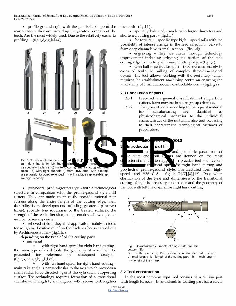
In the most common type tool consists of a cutting part with length lc, neck – ln and shank ls. Cutting part has a screw
Fig. 1. Types single flute end mill cutters [9],[10],[11]: a) right hand; b) left hand spiral for right hand cutting; c) specially ballance; d) for toric cut; e) engraving; g) with ball nose; h) with right chanels; i) from HSS steel with coating; j) sectional; k) conic extended; l) with carbide replaceable tip; m) high-capacity.
Fig. 2. Constructive elements of single flute end mill cutters [2]: D - cutter diameter; Dc - diameter of the mill cutter core; L - total length; lc - length of the cutting part; ln – neck length, ls – length of the shank.
IJSER
International Journal of Scientific & Engineering Research Volume 6, Issue 5, May 2015 1265 ISSN 2229-5518
IJSER © 2015 http://www.ijser.org
flute (body clearance channel). The cutting is performed by a major cutting edge S and a
minor cutting edge S'. They are joined with a core size of which determines the strength of the cutter and the size of chip space. With the increase of the diameter of the core Dc increases the strength and stability of the tool, but the increase, and cutting forces and reducing the space for the chip (flute). Therefore Dc must be considered the minimum permissible by strength considerations.
The shape of the screw flute must provide the required strength of the teeth, enough space to accommodate the chip and to ensure easy and formation and removal. Flute should be smooth, without abrupt transitions, to avoid stress concentration and cracks in the thermal processing. Therefore, the face and major flank of the tooth and the flute butt section is made with parabolic smooth transition. Typically, the width of the grooves in the front projection is taken equal to or slightly larger than the width of the lateral tooth. In view of the applicability of the tools it is recommended that the width of the teeth is of 1,3 ÷ 1,5 times less than that of the flute [2].
The shank is often with cylindrical form. The total length of the cutter is important for its stability and durability. By increasing the length, especially the area outside the zone of attachment, reducing the resistance and durability. In certain critical length, which depends on the diameter and cutting forces, the durability sharply reduced. This calls for different cutting conditions to apply tools with different regulated length or regulated ratio between the length of cutting length - lc to shank - ls (lc/ls) or to adjust the element of the system of cutting.
Single flute end mill cutters with extended cutting part is applied rarely, primarily for inaccessible complex profile surfaces, while those with normal length tail and hard shank are used in intensive feeding regimes and speed on machining centers.
3.3 Tools geometry in static system
The main geometrical parameters of the tool are shown in fig.3. These are: γ0 – orthogonal rake angle, α0 – orthogonal clearance, κr – point angle, ω – helix angle, λs – cutting edge inclination, first and second relief angles - αp1 and αp2 [2].
Defining the tool geometry requires the introduction of virtual planes shown in Figure 4.
Point angle κr is locked between the projection of the major cutting edge S on the plane Pr and to the direction of feeding.
The helix angle ω refers to the outer diameter D and is locked between the sweep of the side cutting edge and the axis of the cutter. The angle ω influences the orthogonal rake angle, the strength of the cutting edge, the shape of the chip and the possibility of being sent by a flute. From the point of view of form and the removal of the chip optimum angle is ω = 30°.
The rake angles γ are provided by the screw itself form the front surface of the tooth. These angles are discussed in tool orthogonal plane Po, minor orthogonal plane Po’ and assumed working plane Pf. The auxiliary rake angle γ0' is variable and depends on the diameter Di of the circle on which lies p.Μ issue, and a number of angular parameters. It is determined by the physico-mechanical properties of manufacturing
material, the type of tools and tooling material. The average value of the auxiliary rake angle in the minor orthogonal plane bu manufacturing of aluminium and its alloys is γo’ = 10÷25°.
The clearance angels the cutting edge is obtained by
grinding. Among them are the most important are auxiliary clearance angles measured in the minor orthogonal plane Po'–α0'. In polyhedral profile-ground style, and the first angle α01' chamfering (site) length fα is locked between the tangent to the minor flank Аα' and cutting edge plane Ps, each subsequent α02', α03', … α0n' is formed as the sum of the transition plus the value of the angle α01'. By relieved style clearance angles are variable and depend on the size regard to the relieving. Usually in the polyhedral profile-ground style tools are considered within limits α01'=8÷12°, while the side flanks instruments is on the order of α0'= 20÷25°.
Fig. 3. Geometrical parameters in static system
Fig. 4. Plains in tools system
IJSER
International Journal of Scientific & Engineering Research Volume 6, Issue 5, May 2015 1266 ISSN 2229-5518
IJSER © 2015 http://www.ijser.org
The cutting edge inclination angle λs, with straight cutting edge lies in tool cutting edge plane and locked between the major cutting edge S and tool preference plane Pr. Normally prima values λs =0÷5°.
In milling with left hand spiral for right hand cutting tool forming a transitional cutting edge length bε between major cutting edge S and minor cutting edge S'.
In single flute end mill cutters interest are more two angles – first axial relief angle αp1 =0÷18° and second axial relief angle αp2 =18÷45°. These are the angels of providing incision of tools. They are depending of the type of manufacturing material and tooling major flank surface.
3.4 Conclusion of part II
3.4.1 Constructive elements and geometric parameters are defined in a static system on a universal, normal with right hand spiral for right hand cutting and polyhedral profile-ground style tool of high speed steel HSS Co8.
3.4.2 The flutes are helical, providing free chip flow from the cutting area. Made with low roughness, free of transitional areas, creating conditions of stress concentration and cracks in the thermal processing.
3.4.3 The geometric parameters are defined constructively or obtained by grinding with abrasive tools.
3.4.4 The provision of normal cutting tool, requires the introduction of additional angels – first and second axial relief angles - αp1 and αp2.
4 PART III – МASUREMENT OF CONSTRUCTIVE ELEMENTS AND GEOMETRIC PARAMETERS
4.1 Introduction in part III In this work are proposed charts solutions for measurement
and subsequent control of constructive and geometric parameters of single flute end mill cutters through the control device - CGCT.01, developed and implemented at the Department MEMETE, Technical University of Sofia, Sliven Engineering-Pedagogical Faculty [3].
A major advantage of this construction compared with many similar possibility with relatively simple mechanisms to to be controlled all constructural and geometric parameters of the single flute end mill cutters. 4.2 Principle of operation of CGCT.01
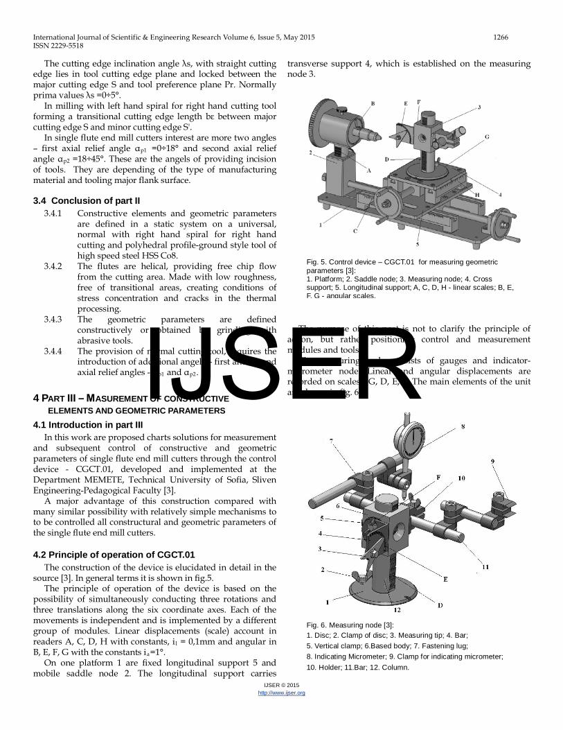
The construction of the device is elucidated in detail in the source [3]. In general terms it is shown in fig.5.
The principle of operation of the device is based on the possibility of simultaneously conducting three rotations and three translations along the six coordinate axes. Each of the movements is independent and is implemented by a different group of modules. Linear displacements (scale) account in readers A, C, D, H with constants, il = 0,1mm and angular in B, E, F, G with the constants ia=1°.
On one platform 1 are fixed longitudinal support 5 and mobile saddle node 2. The longitudinal support carries
transverse support 4, which is established on the measuring node 3.
The purpose of this post is not to clarify the principle of
action, but rather positioning control and measurement modules and tools.
The measuring node consists of gauges and indicator-micrometer node. Linear and angular displacements are recorded on scales - G, D, E, F. The main elements of the unit are shown in fig. 6.
Fig. 5. Control device – CGCT.01 for measuring geometric parameters [3]: 1. Platform; 2. Saddle node; 3. Measuring node; 4. Cross support; 5. Longitudinal support; A, C, D, H - linear scales; B, E, F, G - angular scales.
Fig. 6. Measuring node [3]: 1. Disc; 2. Clamp of disc; 3. Measuring tip; 4. Bar; 5. Vertical clamp; 6.Based body; 7. Fastening lug; 8. Indicating Micrometer; 9. Clamp for indicating micrometer; 10. Holder; 11.Bar; 12. Column.
IJSER
International Journal of Scientific & Engineering Research Volume 6, Issue 5, May 2015 1267 ISSN 2229-5518
IJSER © 2015 http://www.ijser.org
4.3 Measuring and control schemes Constructive elements of single flute end mill cutters D, D',
Dc, L, lc, ln, and ls controlled by appropriate positioning of the measuring tip 3 of the measuring node – fig.7. It abuts the border to account for every linear or diametrical point parameter, then a scale C for longitudinal or H for cross support calipers into account, the current values that are considered to be zero - Lmes1. Follows a longitudinal or transverse movement until another trigger point - Lmes2.
The value of the searches dimensions is determined by
dependence [2]:
1m e s2m e s LLi)D(L −= (1)
Diameter D [mm], D '[mm] and Dc can be measured with a micrometer and directly placed in the clamp for indicating micrometer 9 of the measuring node.
To determine the geometric parameters of the measuring node using fig.8.
Controlling of the point angle angle κr measure - according
to figure 9. The tools establishes a three-jaw chuck in the universal.
With the measuring tip holder rotates about its axis until it reaches a vertical position. Column indicator node is rotated
so that the G scale is reset. Through movement of the supports, the arm of the measuring tip is moved to the top of the router. Scala E is reset.
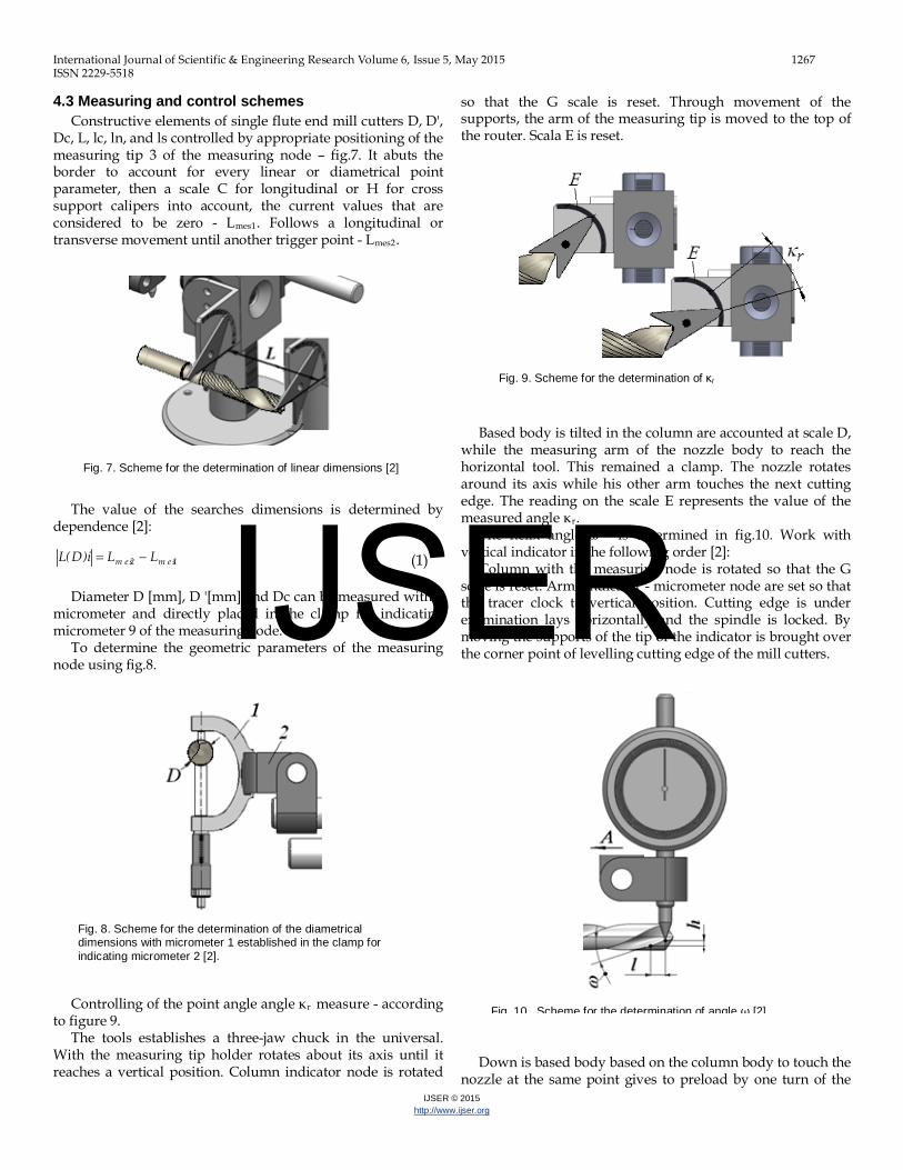
Based body is tilted in the column are accounted at scale D,
while the measuring arm of the nozzle body to reach the horizontal tool. This remained a clamp. The nozzle rotates around its axis while his other arm touches the next cutting edge. The reading on the scale E represents the value of the measured angle κr.
The helix angle ω - is determined in fig.10. Work with vertical indicator in the following order [2]:
Column with the measuring node is rotated so that the G scale is reset. Arms indicator - micrometer node are set so that the tracer clock to vertical position. Cutting edge is under examination lays horizontally and the spindle is locked. By moving the supports of the tip of the indicator is brought over the corner point of levelling cutting edge of the mill cutters.
Down is based body based on the column body to touch the
nozzle at the same point gives to preload by one turn of the
Fig. 7. Scheme for the determination of linear dimensions [2]
Fig. 8. Scheme for the determination of the diametrical dimensions with micrometer 1 established in the clamp for indicating micrometer 2 [2].
Fig. 9. Scheme for the determination of κr
Fig. 10. Scheme for the determination of angle ω [2]
IJSER
International Journal of Scientific & Engineering Research Volume 6, Issue 5, May 2015 1268 ISSN 2229-5518
IJSER © 2015 http://www.ijser.org
indicator, and then the device is reset. Record the reading on the scale of the longitudinal support C. By means of the longitudinal support indicator moves a distance l [mm] in the direction of arrow A, in which the tip of the indicator slide close to the auxiliary cutting edge of the tool.
The indicating micrometer is decline h[mm] screw in the front surface of the cutter. The value of angle ω with sufficient accuracy is determined by a formula:
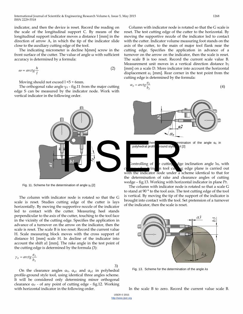
(2) Moving should not exceed l <5 ÷ 6mm. The orthogonal rake angle γ0 - fig.11 from the major cutting
edge S can be measured by the indicator node. Work with vertical indicator in the following order.
The column with indicator node is rotated so that the G
scale is reset. Studies cutting edge of the cutter is lays horizontally. By moving the supportive nozzle of the indicator led to contact with the cutter. Measuring heel stands perpendicular to the axis of the cutter, touching to the tool face in the vicinity of the cutting edge. Specifies the application in advance of a turnover on the arrow on the indicator, then the scale is reset. The scale B is too reset. Record the current value H. Scale measuring block moves with the cross support of distance b1 [mm] scale H. In decline of the indicator into account the shift a1 [mm]. The rake angle in the test point of the cutting edge is determined by the formula (3):
(
3) On the clearance angles α0, αp1 and αp2 in polyhedral
profile-ground style tool, using identical three angles scheme. It will be considered only determining minor orthogonal clearance α0’ - of any point of cutting edge - fig.12. Working with horizontal indicator in the following order.
Column with indicator node is rotated so that the G scale is reset. The test cutting edge of the cutter to the horizontal. By moving the supportive nozzle of the indicator led to contact with the cutter. Indicator volume measuring foot stands on the axis of the cutter, to the main of major tool flank near the cutting edge. Specifies the application in advance of a turnover on the arrow on the indicator, then the scale is reset. The scale B is too reset. Record the current scale value B. Measurement unit moves in a vertical direction distance b2
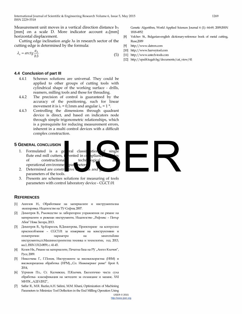
[mm] on a scale D. More indicator into account the horizontal displacement a2 [mm]. Rear corner in the test point from the cutting edge is determined by the formula: (4)
Controlling of the cutting edge inclination angle λs, with
cutting edge lying in tool cutting edge plane is carried out with the indicator node under a scheme identical to that for the determination of rake and clearance angles of cutting wedge – fig.13. Working with horizontal indicator in plane Pr.
The column with indicator node is rotated so that a scale G to stand at 90 ° to the tool axis. The test cutting edge of the tool is vertical. By moving the tip of the support of the indicator is brought into contact with the tool. Set pretension of a turnover of the indicator, then the scale is reset.
In the scale B to zero. Record the current value scale B.
lharctg=ω
Fig. 11. Scheme for the determination of angle γ0 [2]
1
10 b
aarctg=γ
Fig. 12. Scheme for the determination of the angle α0 in polyhedral profile-ground style tool [2]
2
20 b
aarctg=α
Fig. 13. Scheme for the determination of the angle λs
IJSER
International Journal of Scientific & Engineering Research Volume 6, Issue 5, May 2015 1269 ISSN 2229-5518
IJSER © 2015 http://www.ijser.org
Measurement unit moves in a vertical direction distance b3 [mm] on a scale D. More indicator account a3[mm] horizontal displacement.
Cutting edge inclination angle λs in research sector of the cutting edge is determined by the formula:
(5)
4.4 Conclusion of part III
4.4.1 Schemes solutions are universal. They could be applied to other groups of cutting tools with cylindrical shape of the working surface - drills, reamers, milling tools and those for threading.
4.4.2 The precision of control is guaranteed by the accuracy of the positioning, such for linear movement it is i l = 0,1mm and angular ia = 1 °.
4.4.3 Controlling the dimensions through quadrant device is direct, and based on indicators node through simple trigonometric relationships, which is a prerequisite for reducing measurement errors, inherent in a multi control devices with a difficult complex construction.
5 GENERAL CONCLUSION 1. Formulated is a general classification of single
flute end mill cutters, invented in compliance complex of constructional, technological and operational environment parameters.
2. Determined are constructive elements and geometrical parameters of the tools.
3. Presents are schemes solutions for measuring of tools parameters with control laboratory device - CGCT.01
REFERENCES [1] Ангелов Н., Обработване на материалите и инструментална
екипировка. Издателство на ТУ-София, 2007. [2] Димитров В., Ръководство за лабораторни упражнения по рязане на
материалите и режещи инструменти, Издателство „Рефлекс – Петър Абов” Нова Загора, 2013.
[3] Димитров В., Хр.Кирилов, В.Димитрова, Проектиране на контролно приспособление – CGCT.01 за измерване на конструктивни и геометрични параметри на многозъбови инструменти,сп.Машиностроителна техника и технологии, год. 2013, кн.1, ISSN 1312-0859, с. 41-45.
[4] Колев Ив., Рязане на материалите, Печатна база на РУ „Ангел Кънчев”, Русе, 2009.
[5] Николчева Г., Г.Попов, Инструменти за високоскоростна (HSM) и високопрецизна обработка (HPM), „Сп. Инженеринг ревю“ брой 8, 2014,
[6] Угринов Пл., Ст. Калчевски, П.Кънчев, Екологично чиста суха обработка- класификация на методите за охлаждане и мазане, XХI МНТК „АДП-2012”,
[7] Saffar R., M.R. Razfar,A.H. Salimi, M.M. Khani, Optimization of Machining Parameters to Minimize Tool Deflection in the End Milling Operation Using
Genetic Algorithm, World Applied Sciences Journal 6 (1): 64-69, 2009,ISSN 1818-4952
[8] Velchev St., Bulgarian-english dictionary-reference book of metal cutting, Ruse,2009
[9] http://www.datron.com [10] http://www.harveytool.com [11] http://www.astech-tools.com [12] http://epubl.tugab.bg/documents/cat_view/41
3baarctg 3
s =λ
IJSER