1 hydrogen business jet preliminary design review team iii derek dalton megan darraugh sara davia...
Post on 20-Dec-2015
216 views
TRANSCRIPT
1
Hydrogen Business JetPreliminary Design Review
Team III
Derek DaltonMegan Darraugh
Sara DaViaBeau GlimSeth Hahn
Lauren NordstromMark Weaver
2
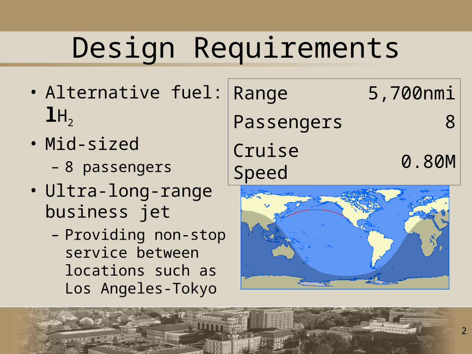
Design Requirements
• Alternative fuel: lH2
• Mid-sized – 8 passengers
• Ultra-long-range business jet – Providing non-stop
service between locations such as Los Angeles-Tokyo
Range 5,700nmi
Passengers 8
Cruise Speed 0.80M
3
Market Overview
• Projected 10-year revenue is $50B for the entire ultra long range market
• Acquire 15% market share within 10 years– Approximately 20 aircraft sold annually– $1.2B in potential annual sales, 2% of total
business aviation market
• Expect to enter market in 2040– Assuming $12B in development costs, will
break even in 10 years
4
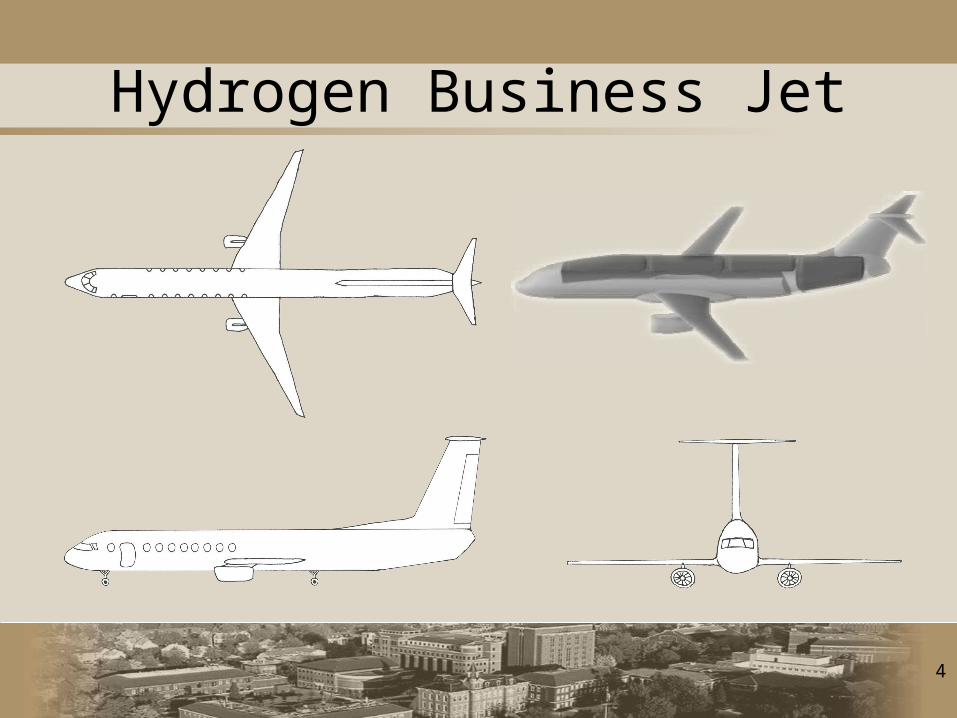
Hydrogen Business Jet
5
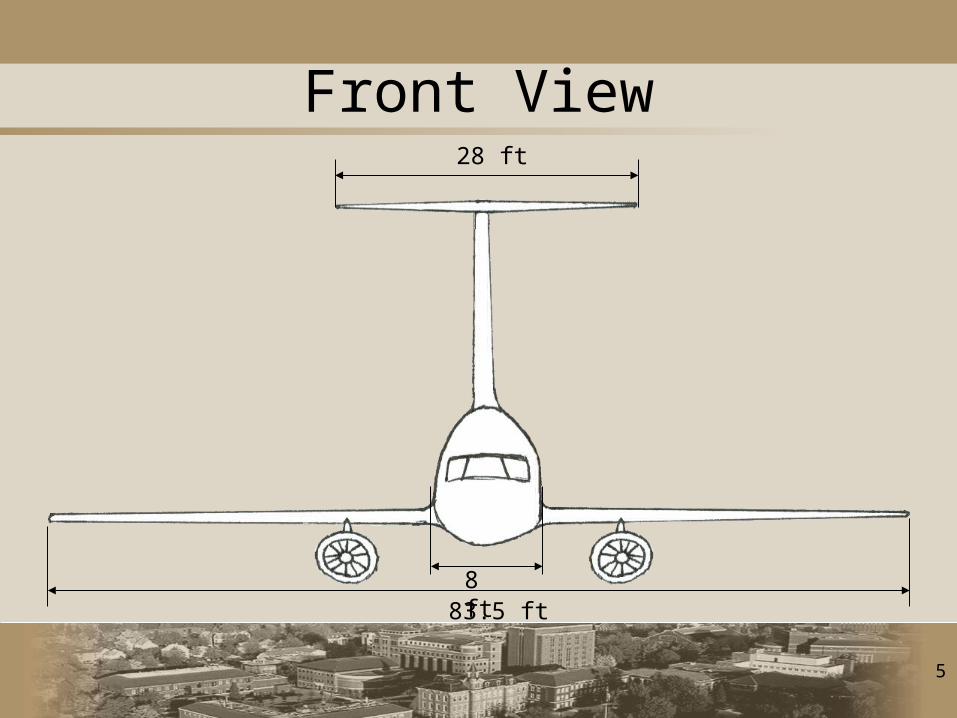
Front View
83.5 ft
28 ft
8 ft
6
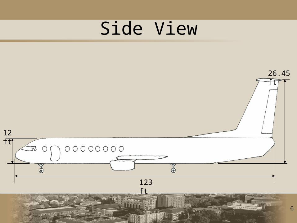
Side View
123 ft
26.45 ft
12 ft
7
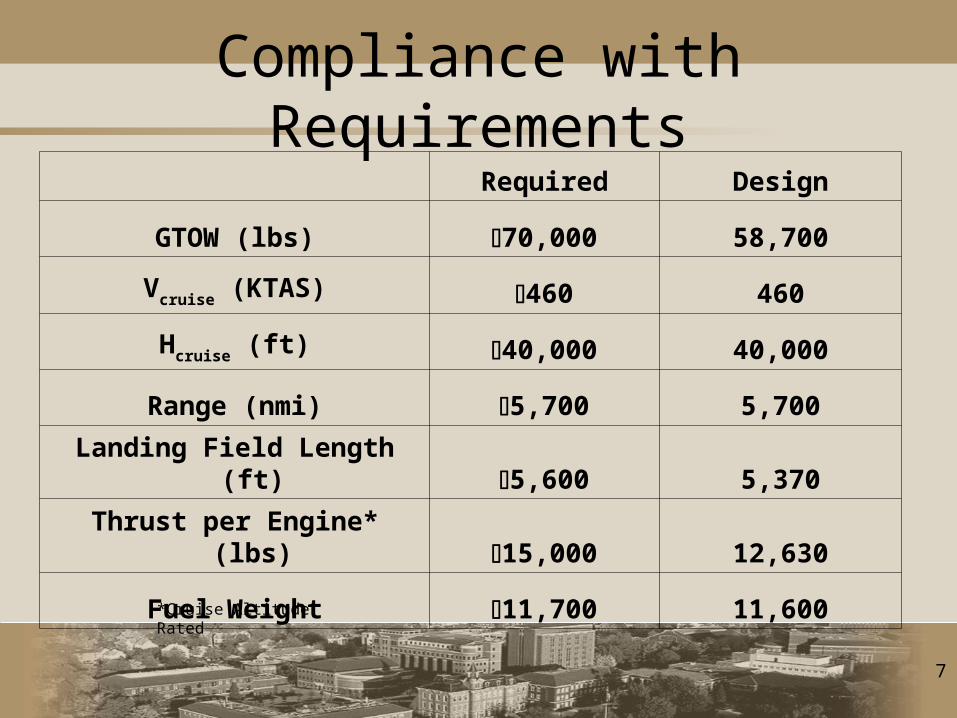
Compliance with Requirements Required Design
GTOW (lbs) 70,000 58,700
Vcruise (KTAS) 460 460
Hcruise (ft) 40,000 40,000
Range (nmi) 5,700 5,700
Landing Field Length (ft) 5,600 5,370
Thrust per Engine* (lbs) 15,000 12,630
Fuel Weight 11,700 11,600*Cruise Altitude Rated
8
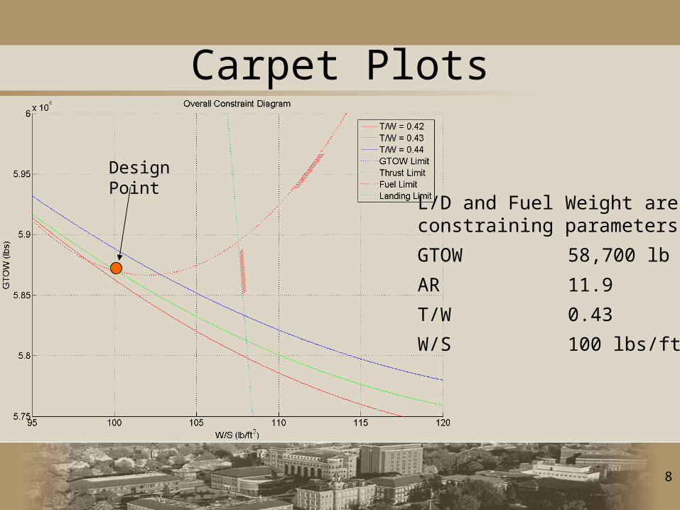
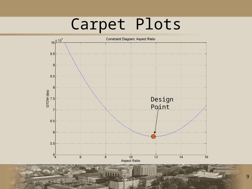
Carpet Plots
L/D and Fuel Weight are constraining parameters
GTOW 58,700 lb
AR 11.9
T/W 0.43
W/S 100 lbs/ft2
Design Point
9
Carpet Plots
Design Point
10
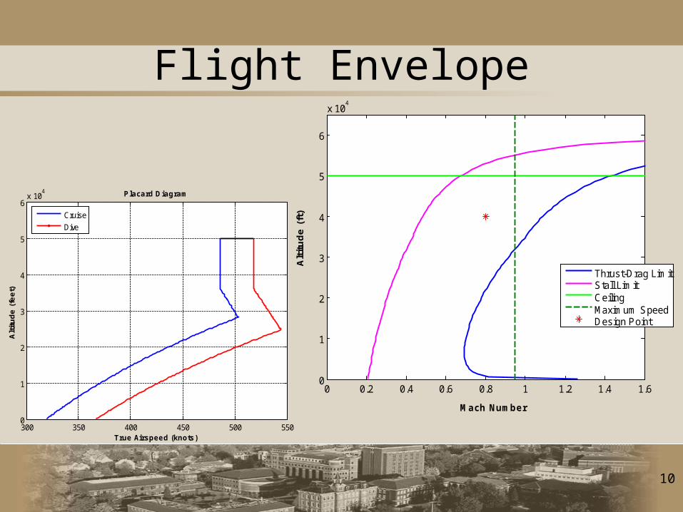
Flight Envelope
0 0.2 0.4 0.6 0.8 1 1.2 1.4 1.60
1
2
3
4
5
6
x 104
Mach Number
Alt
itu
de
(ft
)
Thrust-Drag LimitStall LimitCeilingMaximum SpeedDesign Point
300 350 400 450 500 5500
1
2
3
4
5
6x 10
4 Placard Diagram
True Airspeed (knots)
Alt
itu
de
(fe
et)
Cruise
Dive
11
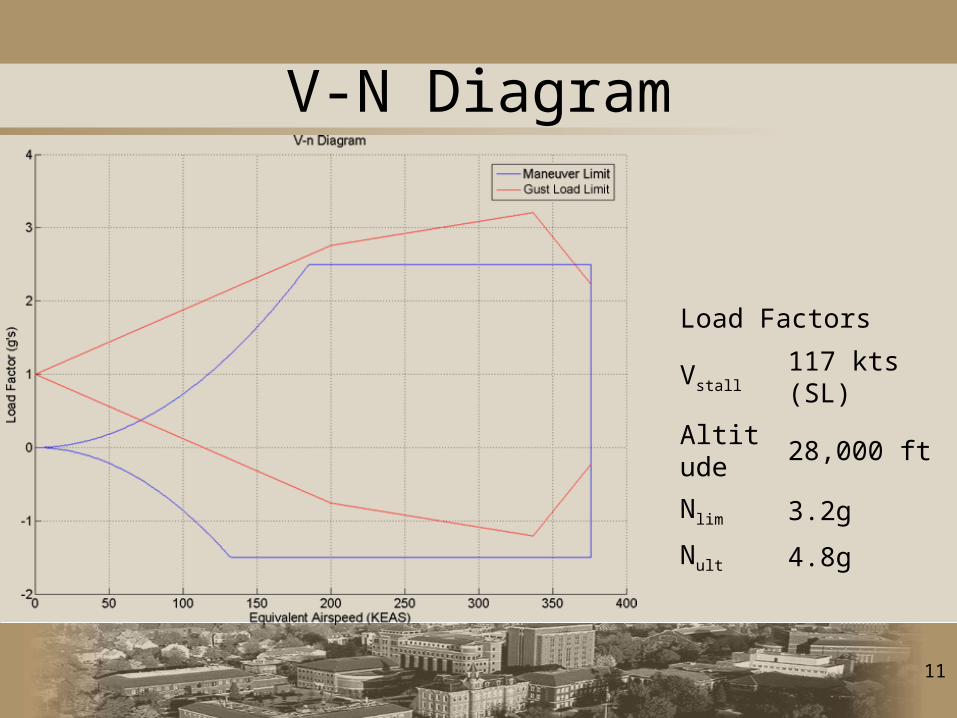
V-N Diagram
Load Factors
Vstall 117 kts (SL)
Altitude 28,000 ft
Nlim 3.2g
Nult 4.8g
12
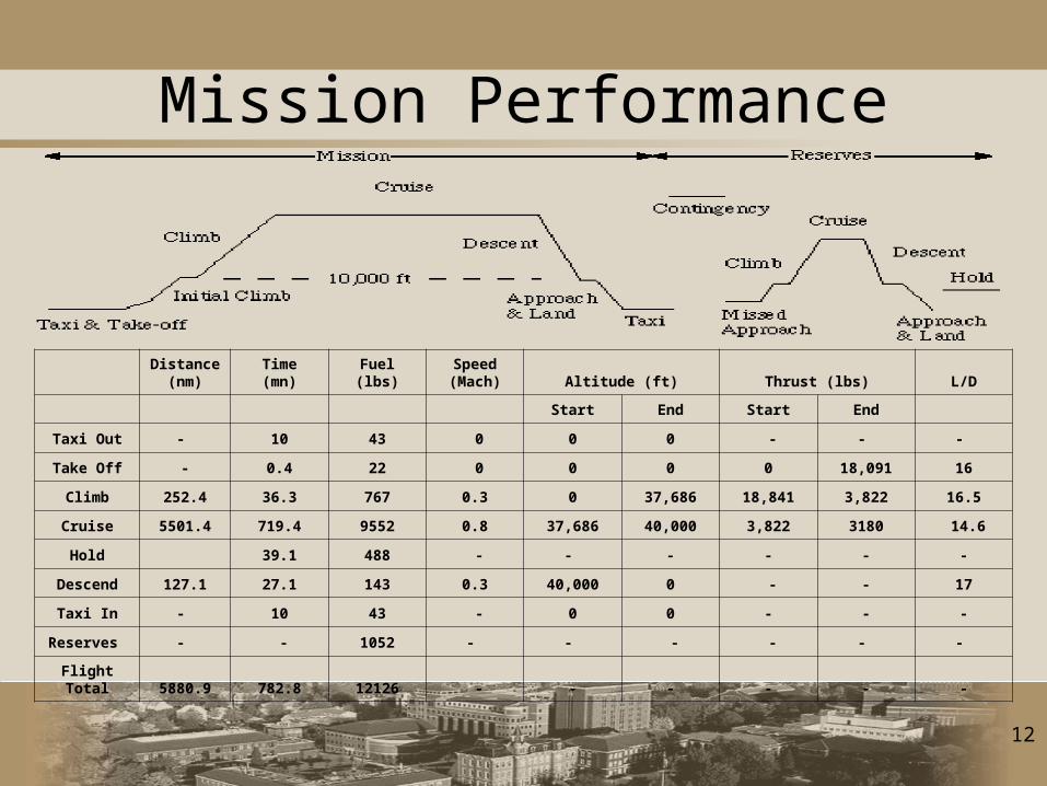
Mission Performance
Distance
(nm) Time (mn) Fuel (lbs)Speed (Mach) Altitude (ft) Thrust (lbs) L/D
Start End Start End
Taxi Out - 10 43 0 0 0 - - -
Take Off - 0.4 22 0 0 0 0 18,091 16
Climb 252.4 36.3 767 0.3 0 37,686 18,841 3,822 16.5
Cruise 5501.4 719.4 9552 0.8 37,686 40,000 3,822 3180 14.6
Hold 39.1 488 - - - - - -
Descend 127.1 27.1 143 0.3 40,000 0 - - 17
Taxi In - 10 43 - 0 0 - - -
Reserves - - 1052 - - - - - -
Flight Total 5880.9 782.8 12126 - - - - - -
13
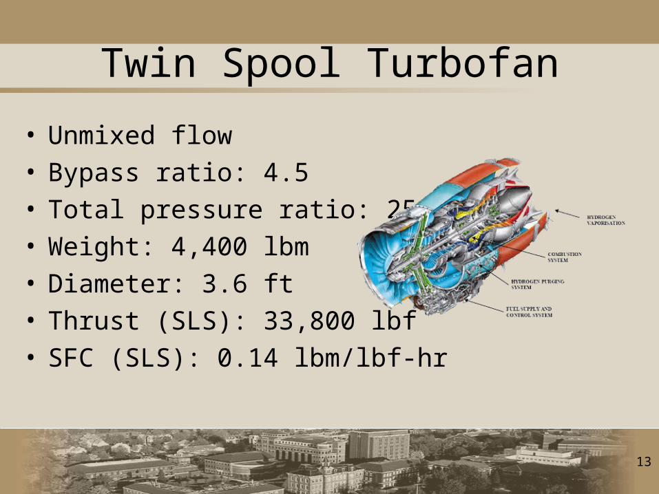
Twin Spool Turbofan
• Unmixed flow• Bypass ratio: 4.5• Total pressure ratio: 25• Weight: 4,400 lbm• Diameter: 3.6 ft• Thrust (SLS): 33,800 lbf• SFC (SLS): 0.14 lbm/lbf-hr
14
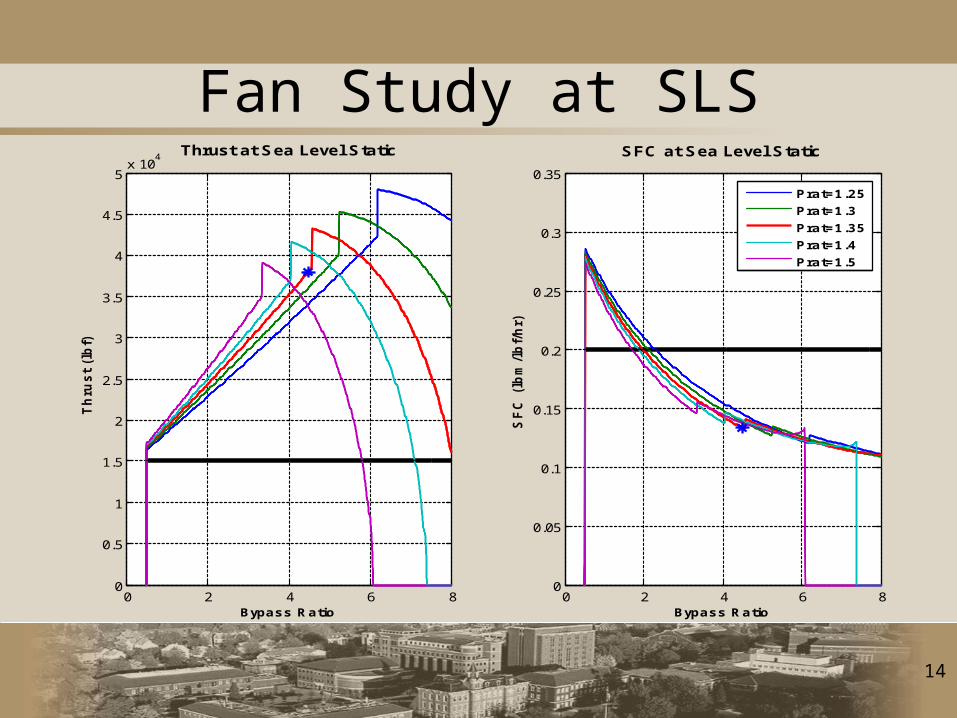
Fan Study at SLS
0 2 4 6 80
0.5
1
1.5
2
2.5
3
3.5
4
4.5
5x 10
4Thrust at Sea Level Static
Bypass Ratio
Th
rus
t (l
bf)
0 2 4 6 80
0.05
0.1
0.15
0.2
0.25
0.3
0.35
SFC at Sea Level Static
Bypass Ratio
SF
C (
lbm
/lb
f/h
r)
Prat=1.25
Prat=1.3
Prat=1.35
Prat=1.4
Prat=1.5

15
Structures & Materials
• Wing & fuselage skin: Carbon Epoxy laminate– Core in laminate adds stiffness
for little additional weight– The laminate can be compared
to an I-beam:• Skins act as the I-beam flange • Core materials act as the beam’s
shear web
• Pylons: Titanium (Ti – 6Al- 4V)– Good for high load, poor shear
properties
16
Structures & Materials
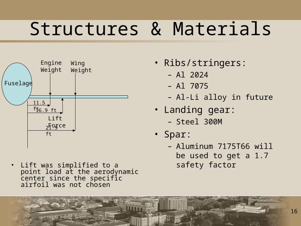
• Lift was simplified to a point load at the aerodynamic center since the specific airfoil was not chosen
Engine Weight
Wing Weight
Lift Force
11.5 ft
16.9 ft
21.5 ft
Fuselage
• Ribs/stringers: – Al 2024– Al 7075– Al-Li alloy in future
• Landing gear:– Steel 300M
• Spar:– Aluminum 7175T66 will be
used to get a 1.7 safety factor
17
Landing Gear
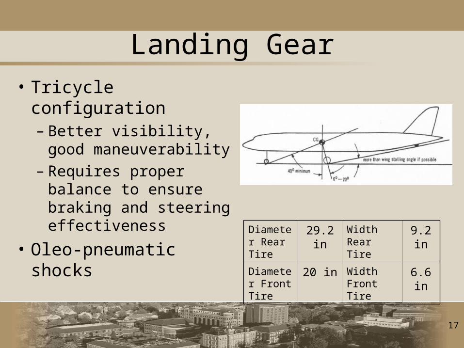
• Tricycle configuration– Better visibility, good
maneuverability– Requires proper
balance to ensure braking and steering effectiveness
• Oleo-pneumatic shocks
Diameter Rear Tire
29.2 in Width Rear Tire
9.2 in
Diameter Front Tire
20 in Width Front Tire
6.6 in
18
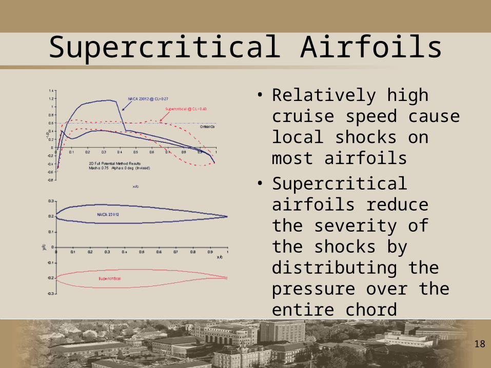
Supercritical Airfoils
• Relatively high cruise speed cause local shocks on most airfoils
• Supercritical airfoils reduce the severity of the shocks by distributing the pressure over the entire chord
19
Airfoil Selection
• Unable to choose an airfoil because of limited data available on specific supercritical airfoils
• Most aircraft with transonic cruise have airfoils tailored to their specific mission
20
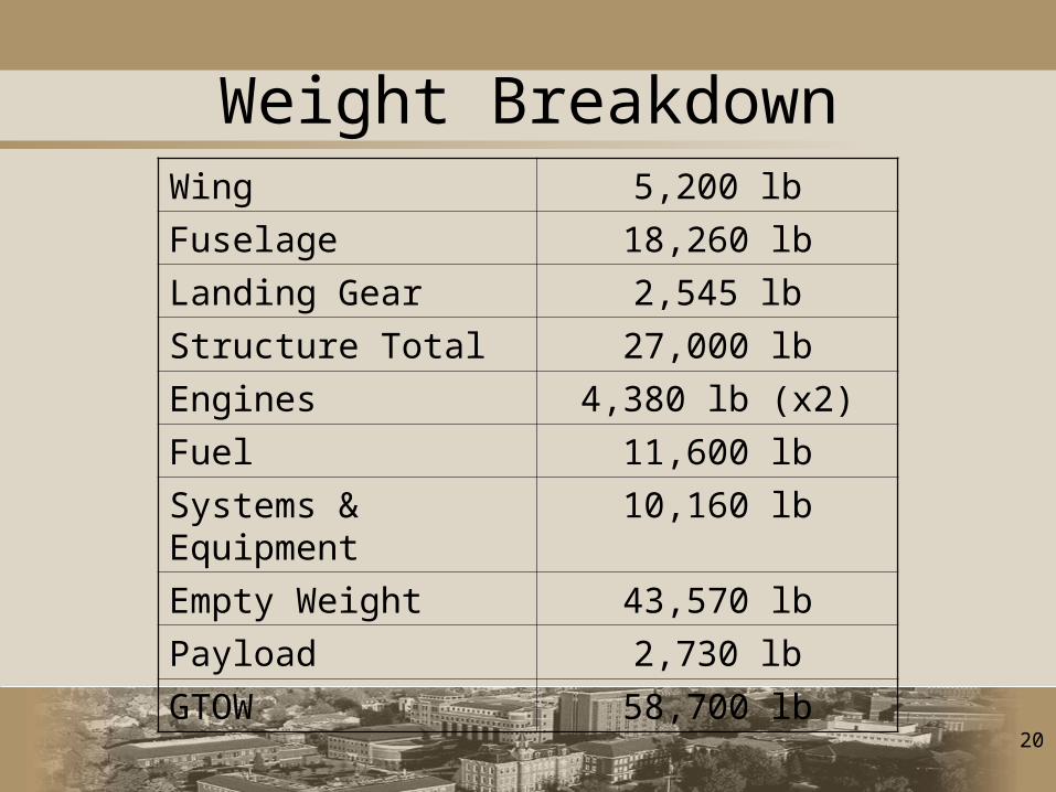
Weight BreakdownWing 5,200 lb
Fuselage 18,260 lb
Landing Gear 2,545 lb
Structure Total 27,000 lb
Engines 4,380 lb (x2)
Fuel 11,600 lb
Systems & Equipment 10,160 lb
Empty Weight 43,570 lb
Payload 2,730 lb
GTOW 58,700 lb
21
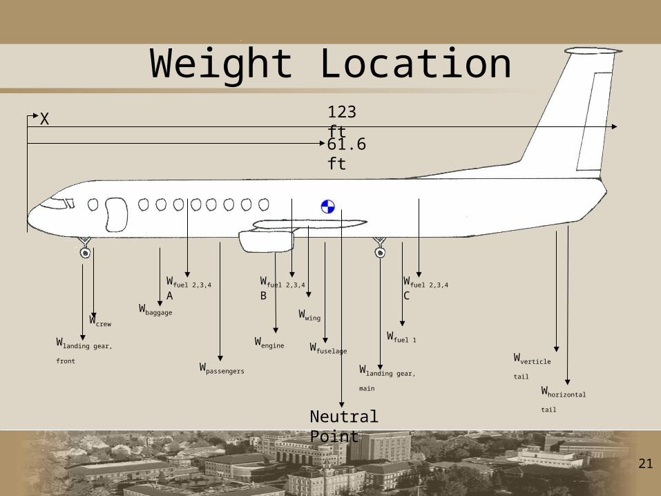
Wlanding gear, front
Wpassengers
WbaggageWcrew
Wfuel 2,3,4 A
Wfuel 1
Wlanding gear, main
Wverticle tail
Whorizontal tail
Wwing
Wengine Wfuselage
Weight LocationX 123 ft
61.6 ft
Wfuel 2,3,4 CWfuel 2,3,4 B
Neutral Point
22
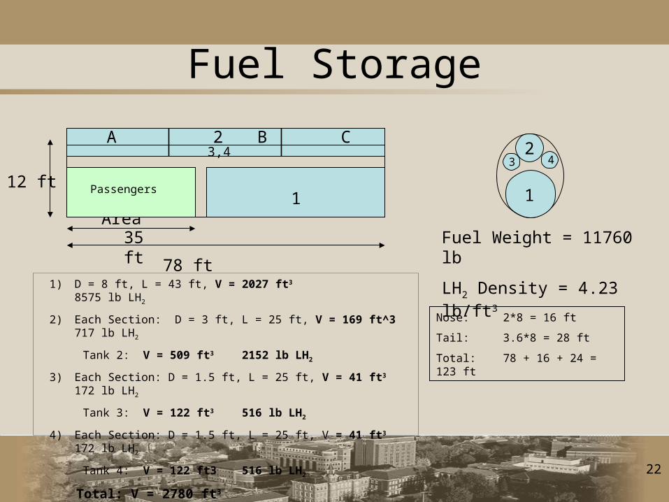
Fuel Storage
12 ft
78 ft
35 ft
8 ftPax Area
3,42
1Passengers
243
1
1) D = 8 ft, L = 43 ft, V = 2027 ft3 8575 lb LH2
2) Each Section: D = 3 ft, L = 25 ft, V = 169 ft^3 717 lb LH2
Tank 2: V = 509 ft3 2152 lb LH2
3) Each Section: D = 1.5 ft, L = 25 ft, V = 41 ft3 172 lb LH2
Tank 3: V = 122 ft3 516 lb LH2
4) Each Section: D = 1.5 ft, L = 25 ft, V = 41 ft3 172 lb LH2
Tank 4: V = 122 ft3 516 lb LH2
Total: V = 2780 ft3 11760 lb LH2
Nose: 2*8 = 16 ft
Tail: 3.6*8 = 28 ft
Total: 78 + 16 + 24 = 123 ft
Fuel Weight = 11760 lb
LH2 Density = 4.23 lb/ft3
A B C
23
40000.00
42000.00
44000.00
46000.00
48000.00
50000.00
52000.00
54000.00
56000.00
58000.00
59.00 60.00 61.00 62.00 63.00 64.00 65.00
C.G. Location From Nose (ft)
We
igh
t (l
bs
)
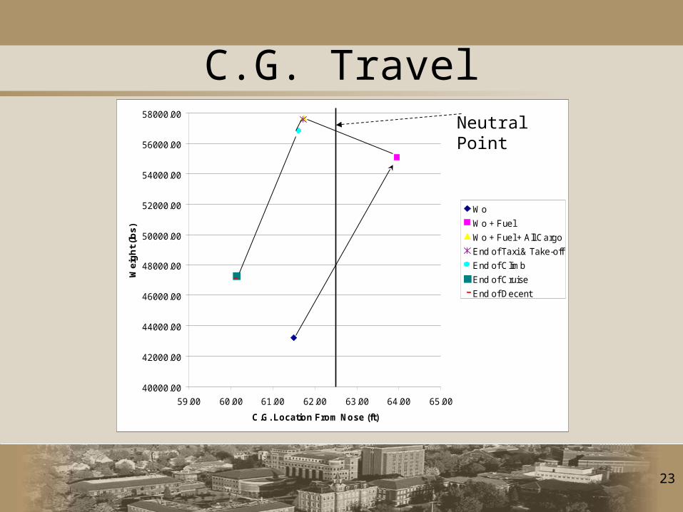
Wo
Wo + Fuel
Wo + Fuel + All Cargo
End of Taxi & Take-off
End of Climb
End of Cruise
End of Decent
C.G. TravelNeutral Point
24
Dynamic Stability
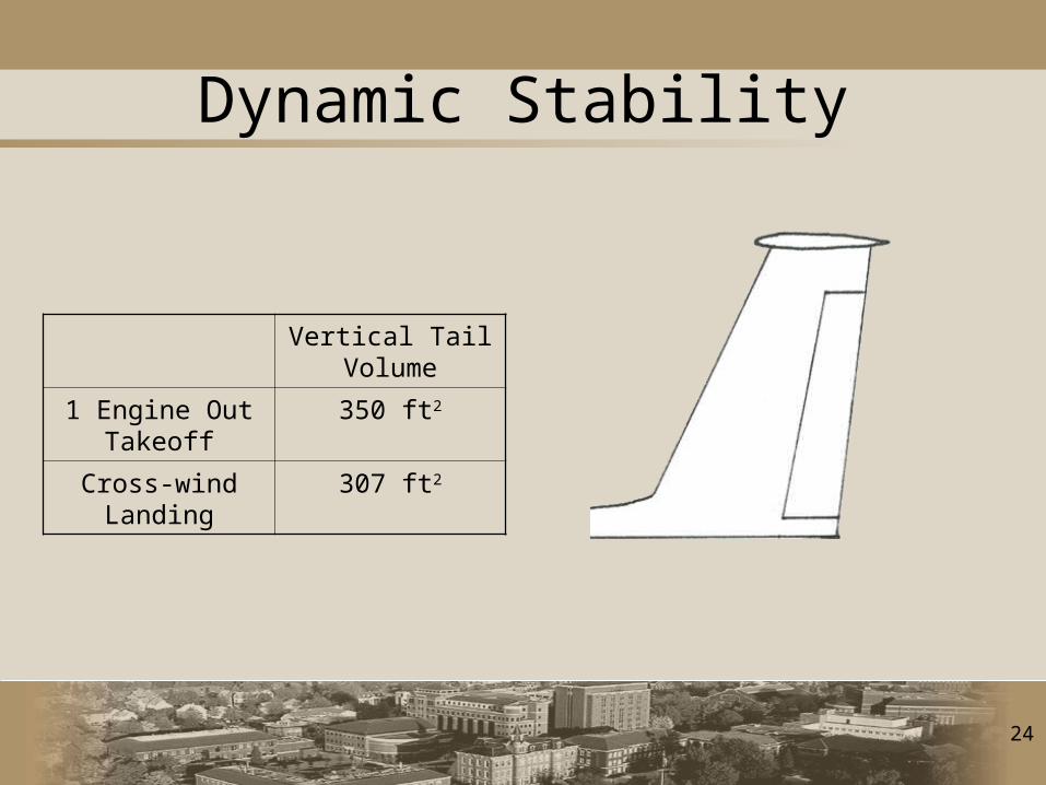
Vertical Tail Volume
1 Engine Out Takeoff
350 ft2
Cross-wind Landing
307 ft2
25
Cost
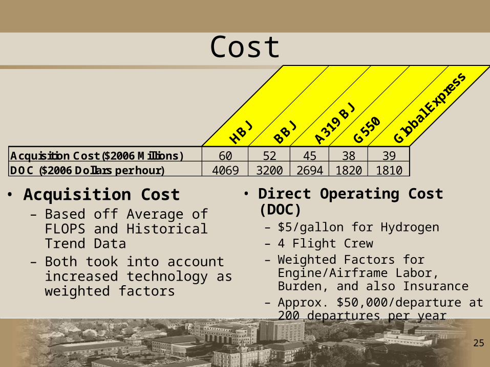
• Acquisition Cost– Based off Average of FLOPS
and Historical Trend Data– Both took into account
increased technology as weighted factors
• Direct Operating Cost (DOC)– $5/gallon for Hydrogen– 4 Flight Crew– Weighted Factors for
Engine/Airframe Labor, Burden, and also Insurance
– Approx. $50,000/departure at 200 departures per year
HBJBBJ
A319
BJ
G550
Global
Exp
ress
Acquisition Cost ($2006 Millions) 60 52 45 38 39DOC ($2006 Dollars per hour) 4069 3200 2694 1820 1810
26
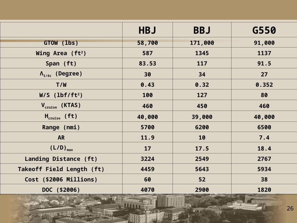
HBJ BBJ G550GTOW (lbs) 58,700 171,000 91,000
Wing Area (ft2) 587 1345 1137
Span (ft) 83.53 117 91.5
Λ1/4c (Degree) 30 34 27
T/W 0.43 0.32 0.352
W/S (lbf/ft2) 100 127 80
Vcruise (KTAS) 460 450 460
Hcruise (ft) 40,000 39,000 40,000
Range (nmi) 5700 6200 6500
AR 11.9 10 7.4
(L/D)max 17 17.5 18.4
Landing Distance (ft) 3224 2549 2767
Takeoff Field Length (ft) 4459 5643 5934
Cost ($2006 Millions) 60 52 38
DOC ($2006) 4070 2900 1820

27
Outstanding Issues
• Stability
• Airfoil Selection and Aerodynamic Analysis
• Detailed Structural Analysis
• FAA Certification
• Research and Development Cost Analysis

28
Questions

29
30
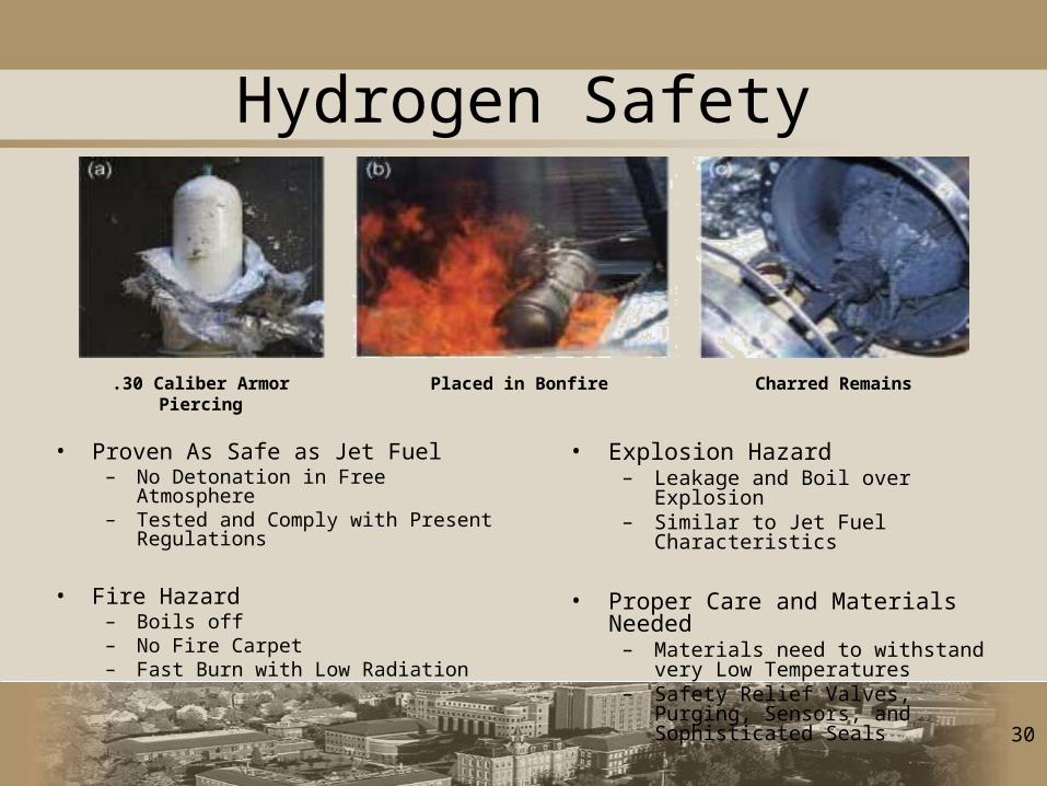
Hydrogen Safety
• Explosion Hazard– Leakage and Boil over Explosion– Similar to Jet Fuel Characteristics
• Proper Care and Materials Needed– Materials need to withstand very Low
Temperatures– Safety Relief Valves, Purging,
Sensors, and Sophisticated Seals
• Proven As Safe as Jet Fuel– No Detonation in Free Atmosphere– Tested and Comply with Present
Regulations
• Fire Hazard– Boils off– No Fire Carpet– Fast Burn with Low Radiation
.30 Caliber Armor Piercing Placed in Bonfire Charred Remains
31
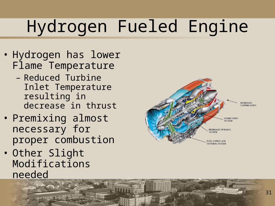
Hydrogen Fueled Engine
• Hydrogen has lower Flame Temperature– Reduced Turbine Inlet
Temperature resulting in decrease in thrust
• Premixing almost necessary for proper combustion
• Other Slight Modifications needed
32
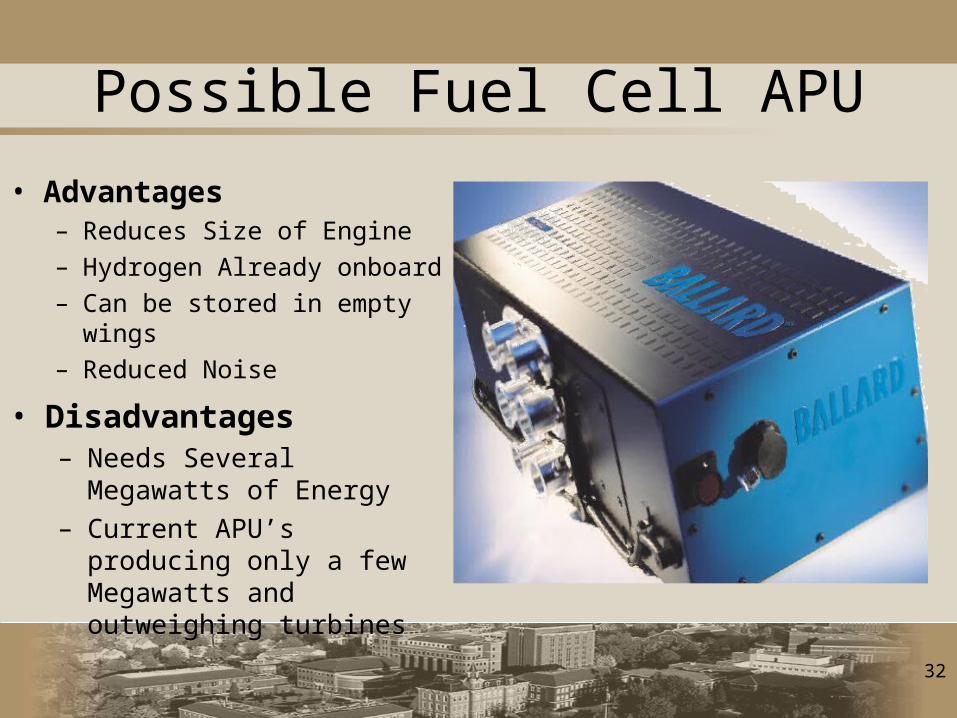
Possible Fuel Cell APU
• Advantages– Reduces Size of Engine– Hydrogen Already onboard– Can be stored in empty wings– Reduced Noise
• Disadvantages– Needs Several Megawatts of
Energy– Current APU’s producing
only a few Megawatts and outweighing turbines
33
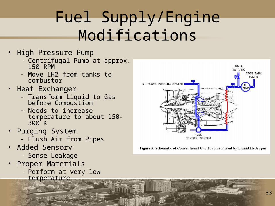
Fuel Supply/Engine Modifications
• High Pressure Pump – Centrifugal Pump at approx. 150
RPM– Move LH2 from tanks to
combustor• Heat Exchanger
– Transform Liquid to Gas before Combustion
– Needs to increase temperature to about 150-300 K
• Purging System– Flush Air from Pipes
• Added Sensory– Sense Leakage
• Proper Materials– Perform at very low temperature
34
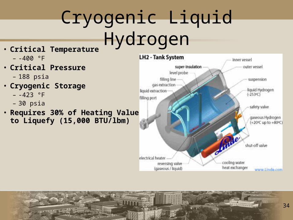
Cryogenic Liquid Hydrogen• Critical Temperature
– -400 °F
• Critical Pressure– 188 psia
• Cryogenic Storage– -423 °F– 30 psia
• Requires 30% of Heating Value to Liquefy (15,000 BTU/lbm)
35
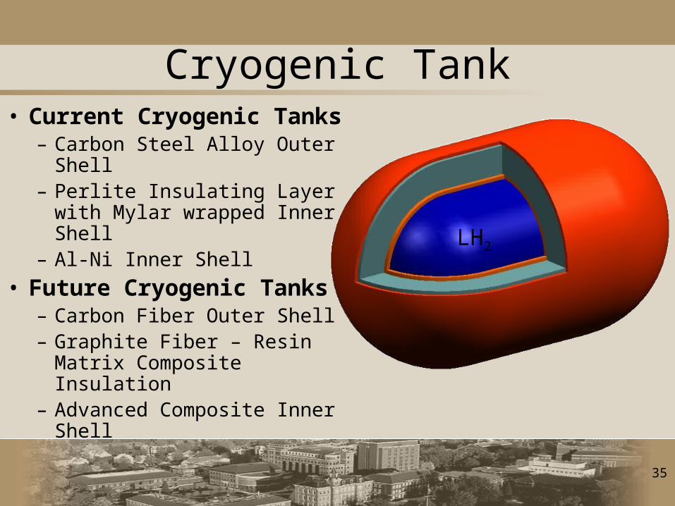
Cryogenic Tank• Current Cryogenic Tanks
– Carbon Steel Alloy Outer Shell
– Perlite Insulating Layer with Mylar wrapped Inner Shell
– Al-Ni Inner Shell
• Future Cryogenic Tanks– Carbon Fiber Outer Shell– Graphite Fiber – Resin Matrix
Composite Insulation– Advanced Composite Inner
Shell
LH2
36
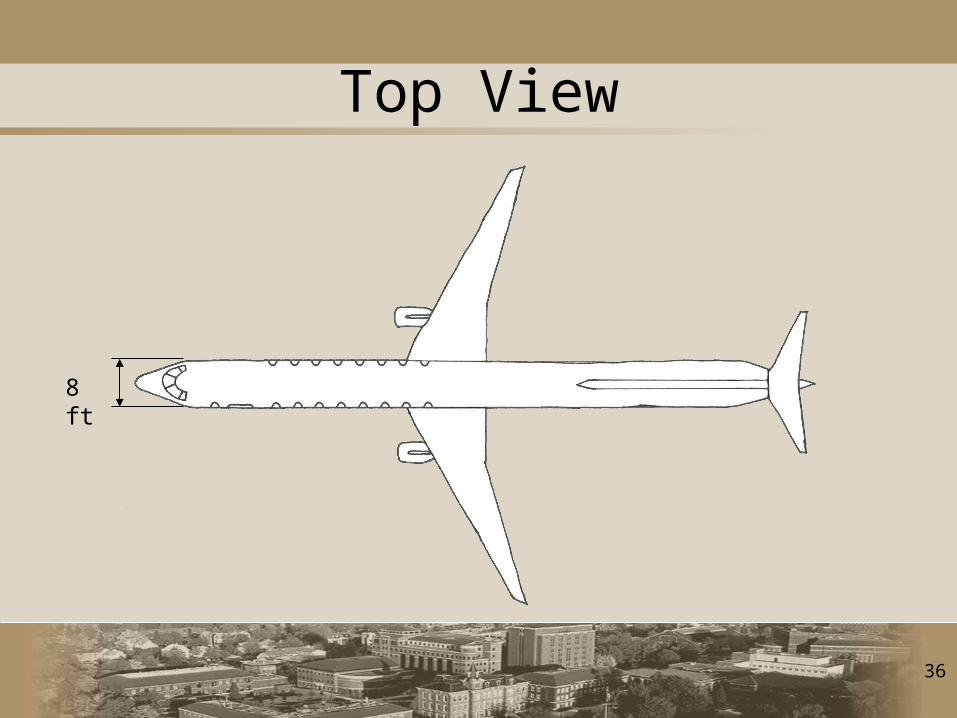
Top View
8 ft
37
FLOPS Input
• Moved Fuel from Wings to Fuselage
• Modified Heating Value to 54,000 BTU/lbm
• Added Composite Wing and Fraction of Structure
• Additional Weighted Factors for Fuel System to Include Cryogenics
• Increased Cost of Labor and Material
38
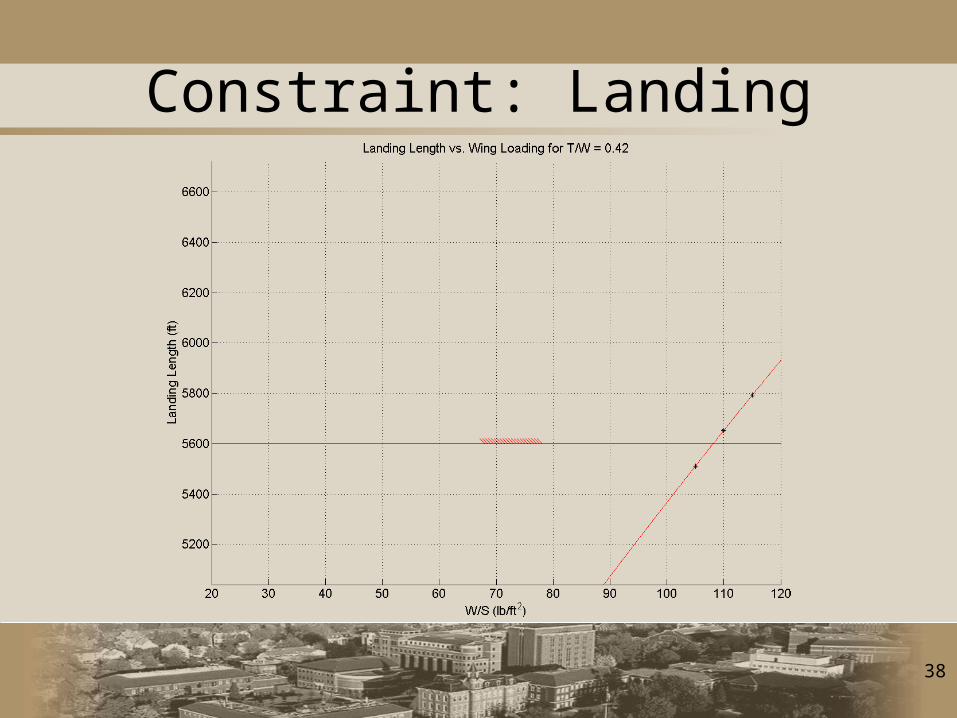
Constraint: Landing

39
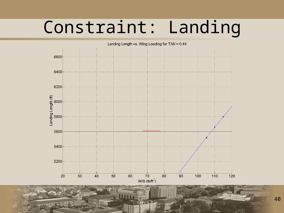
Constraint: Landing
40
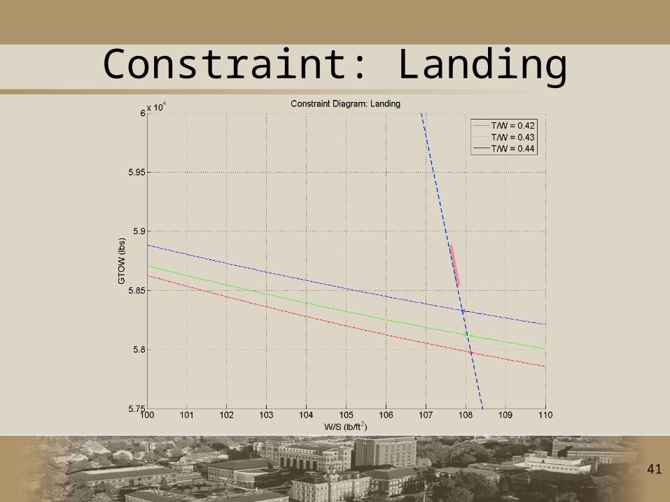
Constraint: Landing
41
Constraint: Landing
42
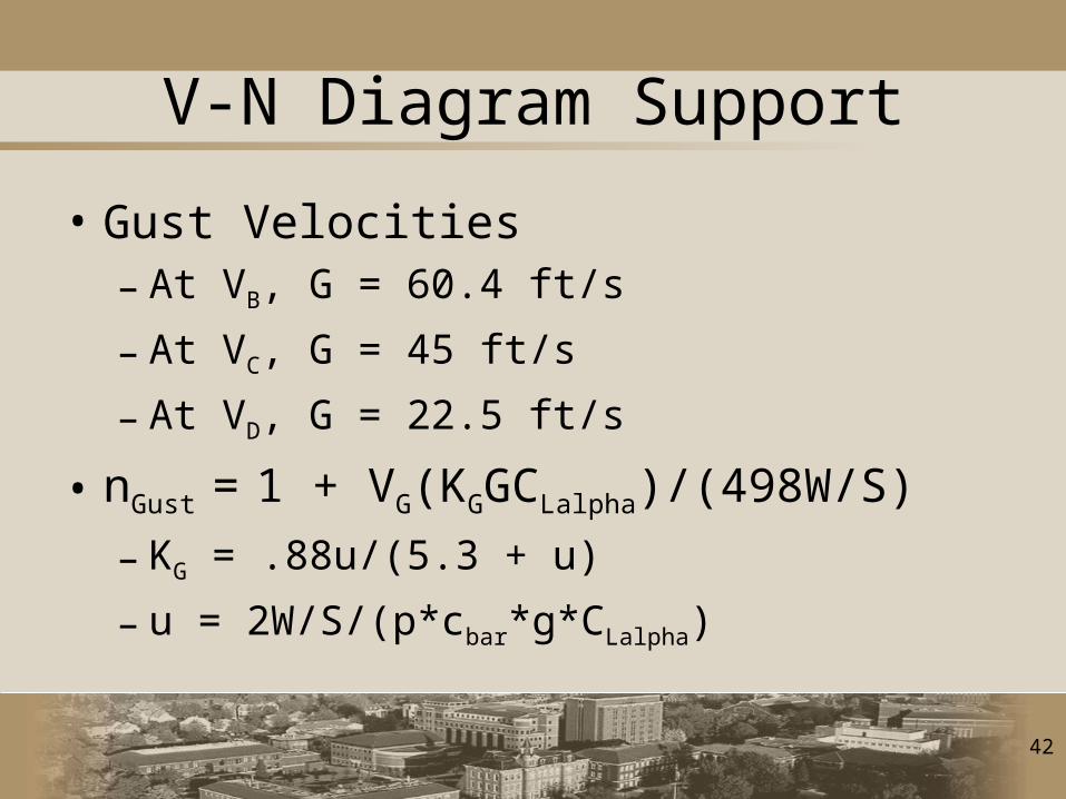
V-N Diagram Support
• Gust Velocities– At VB, G = 60.4 ft/s
– At VC, G = 45 ft/s
– At VD, G = 22.5 ft/s
• nGust = 1 + VG(KGGCLalpha)/(498W/S)
– KG = .88u/(5.3 + u)
– u = 2W/S/(p*cbar*g*CLalpha)
43
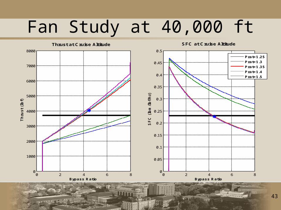
Fan Study at 40,000 ft
0 2 4 6 80
1000
2000
3000
4000
5000
6000
7000
8000
Thrust at Cruise Altitude
Bypass Ratio
Th
rus
t (l
bf)
0 2 4 6 80
0.05
0.1
0.15
0.2
0.25
0.3
0.35
0.4
0.45
0.5
SFC at Cruise Altitude
Bypass Ratio
SF
C (
lbm
/lb
f/h
r)
Prat=1.25
Prat=1.3
Prat=1.35
Prat=1.4
Prat=1.5

44
Engine Code Validation
Bypass Ratio
Pressure Ratio
Thrust (SLS)
Thrust (11 km)
SFC (11 km)
Cryoplane Engine 5.2 36.63 129.5 kN 24.77 kN
5.502 kg/(s-MN)
HBJ Engine Code 5.2 36.6 121.2 kN 33.3 kN
6.2 kg/(s-MN)
45
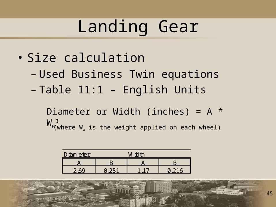
Landing Gear
• Size calculation– Used Business Twin equations– Table 11:1 – English Units
Diameter WidthA B A B
2.69 0.251 1.17 0.216
Diameter or Width (inches) = A * WwB
(where Ww is the weight applied on each wheel)
46
Structural Layout
• Guidelines– Never attach to skin alone– Structural members should not pass through
cabins, air inlets, etc– Attach engine, landing gear, seats, etc to existing
structural member– Design redundancy into structure– Mount control surfaces to spar
• Carry-through wing• Added structural complexity with tanks above
main cabin

47
Spar Calculation
48
Stability Formulas
Add cg equ. Xbar=xi*Wi/Wi
Static margin formula = Xn-X bar/C bar
Equ for VHT
49
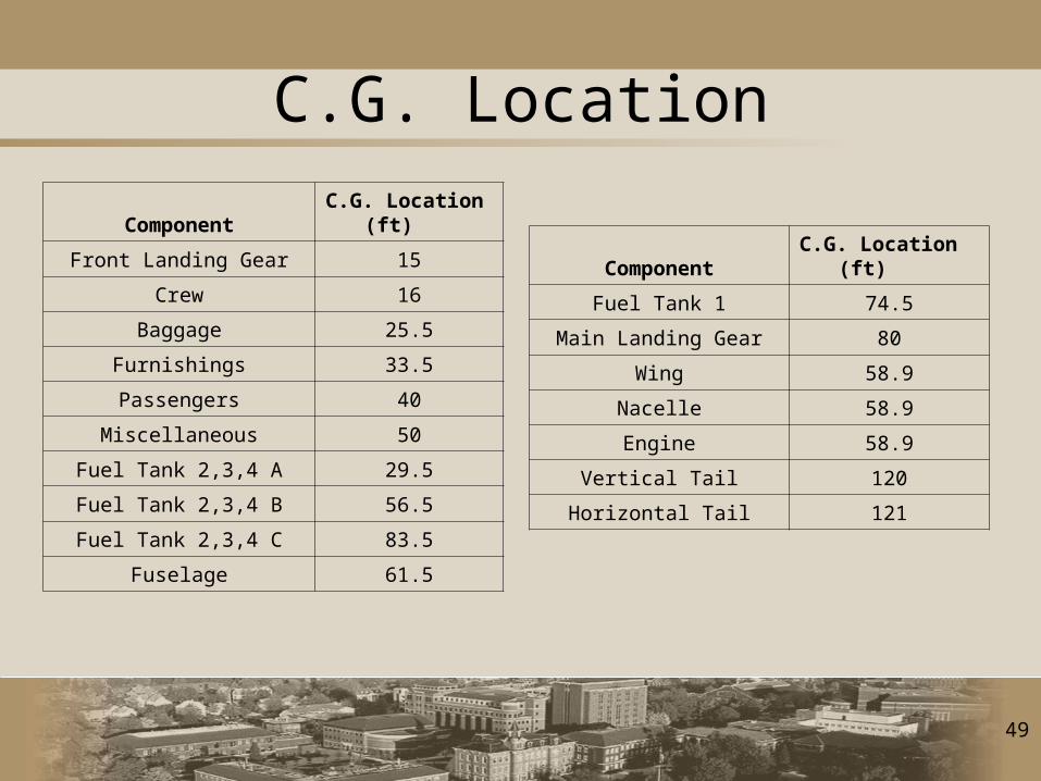
Component C.G. Location (ft)
Front Landing Gear 15
Crew 16
Baggage 25.5
Furnishings 33.5
Passengers 40
Miscellaneous 50
Fuel Tank 2,3,4 A 29.5
Fuel Tank 2,3,4 B 56.5
Fuel Tank 2,3,4 C 83.5
Fuselage 61.5
Component C.G. Location (ft)
Fuel Tank 1 74.5
Main Landing Gear 80
Wing 58.9
Nacelle 58.9
Engine 58.9
Vertical Tail 120
Horizontal Tail 121
C.G. Location
50
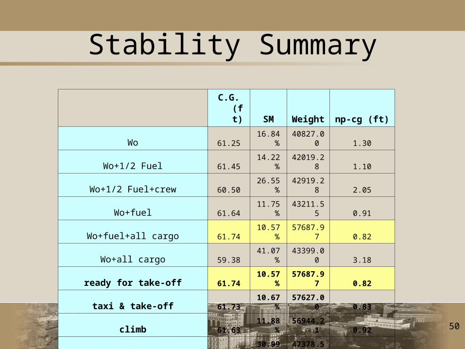
Stability Summary
C.G. (ft) SM Weight np-cg (ft)
Wo 61.25 16.84% 40827.00 1.30
Wo+1/2 Fuel 61.45 14.22% 42019.28 1.10
Wo+1/2 Fuel+crew 60.50 26.55% 42919.28 2.05
Wo+fuel 61.64 11.75% 43211.55 0.91
Wo+fuel+all cargo 61.74 10.57% 57687.97 0.82
Wo+all cargo 59.38 41.07% 43399.00 3.18
ready for take-off 61.74 10.57% 57687.97 0.82
taxi & take-off 61.73 10.67% 57627.00 0.83
climb 61.63 11.88% 56944.21 0.92
cruise 60.16 30.99% 47378.55 2.40
decent 60.12 31.40% 47260.55 2.43
51
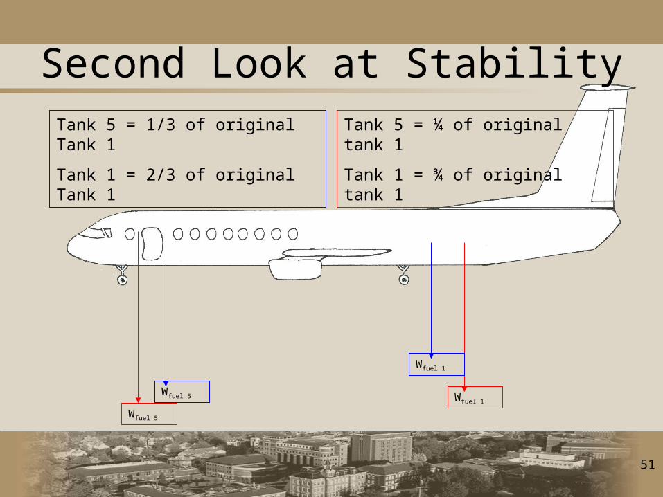
Second Look at Stability
Wfuel 1
Wfuel 1Wfuel 5
Wfuel 5
Tank 5 = ¼ of original tank 1
Tank 1 = ¾ of original tank 1
Tank 5 = 1/3 of original Tank 1
Tank 1 = 2/3 of original Tank 1
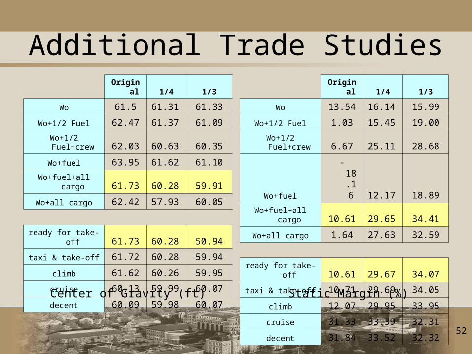
52
Additional Trade Studies Original 1/4 1/3
Wo 61.5 61.31 61.33
Wo+1/2 Fuel 62.47 61.37 61.09
Wo+1/2 Fuel+crew 62.03 60.63 60.35
Wo+fuel 63.95 61.62 61.10
Wo+fuel+all cargo 61.73 60.28 59.91
Wo+all cargo 62.42 57.93 60.05
ready for take-off 61.73 60.28 50.94
taxi & take-off 61.72 60.28 59.94
climb 61.62 60.26 59.95
cruise 60.13 59.99 60.07
decent 60.09 59.98 60.07
Original 1/4 1/3
Wo 13.54 16.14 15.99
Wo+1/2 Fuel 1.03 15.45 19.00
Wo+1/2 Fuel+crew 6.67 25.11 28.68
Wo+fuel -18.16 12.17 18.89
Wo+fuel+all cargo 10.61 29.65 34.41
Wo+all cargo 1.64 27.63 32.59
ready for take-off 10.61 29.67 34.07
taxi & take-off 10.71 29.69 34.05
climb 12.07 29.95 33.95
cruise 31.33 33.39 32.31
decent 31.84 33.52 32.32
Center of Gravity (ft) Static Margin (%)
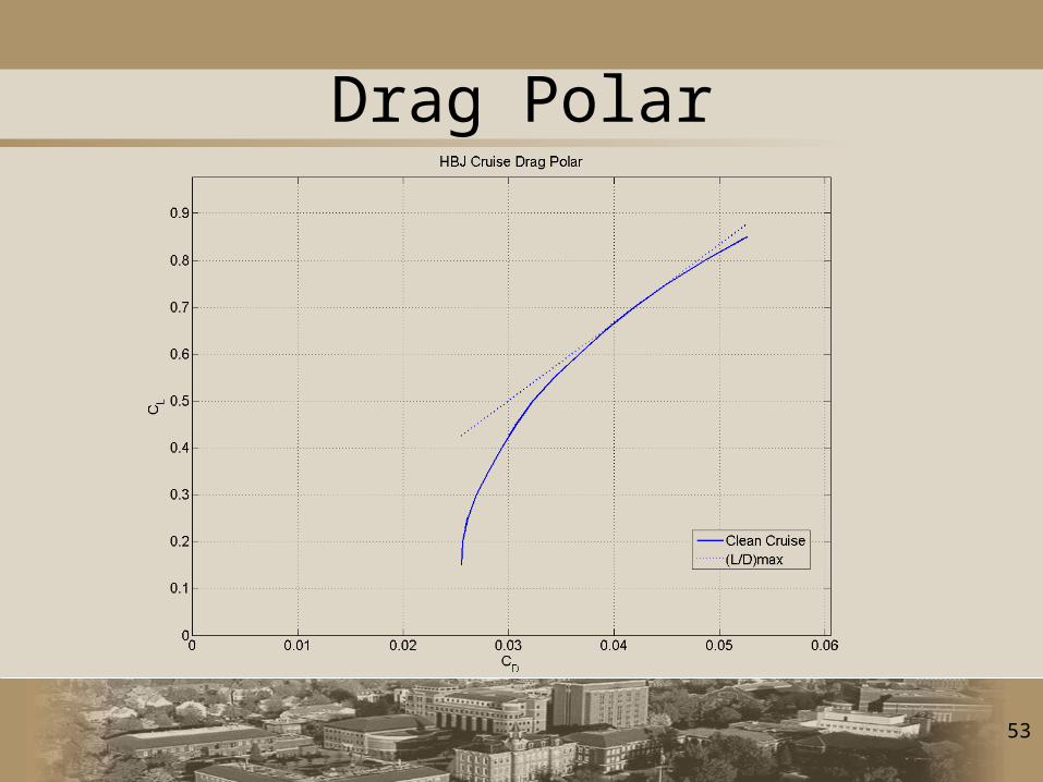
53
Drag Polar

54
1 Engine Out Calculations
• Fv = qv*Sv*CFβv*βv/β*δR
– qv (dynamic pressure at sea-level) = 48.61 slug/(ft*sec2)
– Sv (vertical tail area) ft2
– CFβv (tail lateral lift force coefficient) = 0.55
βv/β (free stream angle change) = 0.99
– δR (rudder deflection) = 0.35 radians
• T (thrust from 1 engine) = 12500 lbf
• M (total moment) = T*dE-Fv*dV = 0
– Calculate with distances from center of gravity. Solve for needed vertical tail area.
55
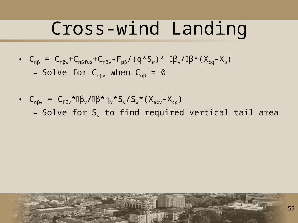
Cross-wind Landing
• Cnβ = Cnβw+Cnβfus+Cnβv-Fpβ/(q*Sw)* βv/β*(Xcg-Xp)
– Solve for Cnβv when Cnβ = 0
• Cnβv = CFβv*βv/β*ηv*Sv/Sw*(Xacv-Xcg)
– Solve for Sv to find required vertical tail area
56
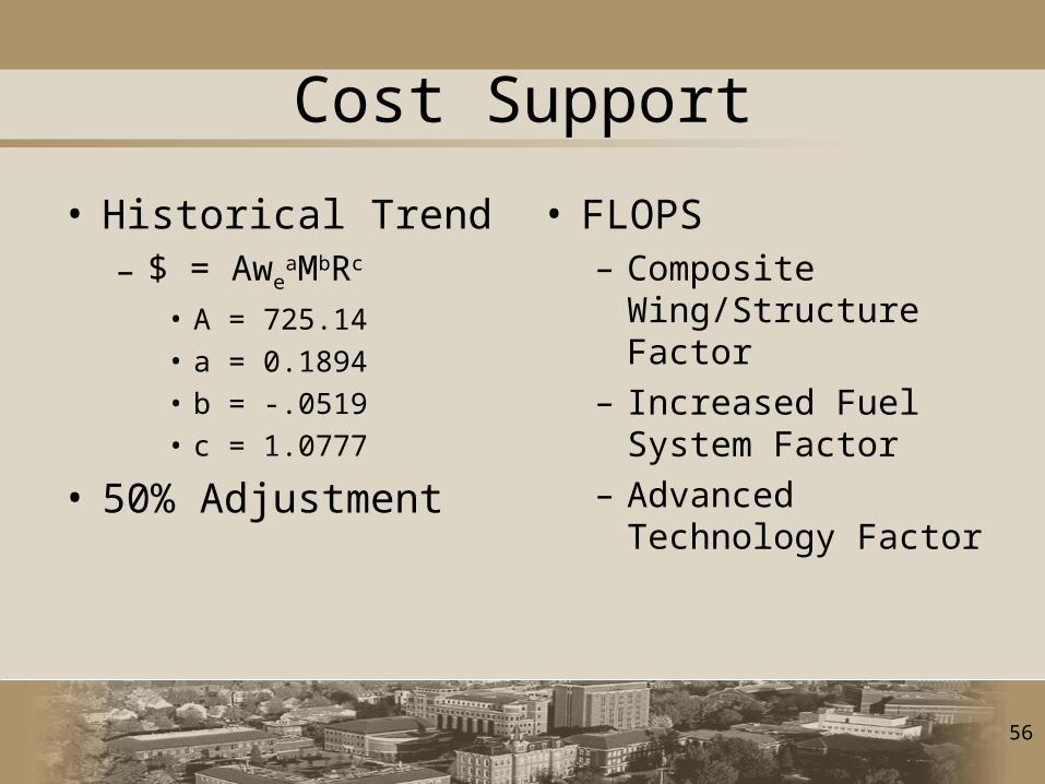
Cost Support
• Historical Trend– $ = Awe
aMbRc
• A = 725.14• a = 0.1894• b = -.0519• c = 1.0777
• 50% Adjustment
• FLOPS– Composite
Wing/Structure Factor– Increased Fuel
System Factor– Advanced Technology
Factor
57
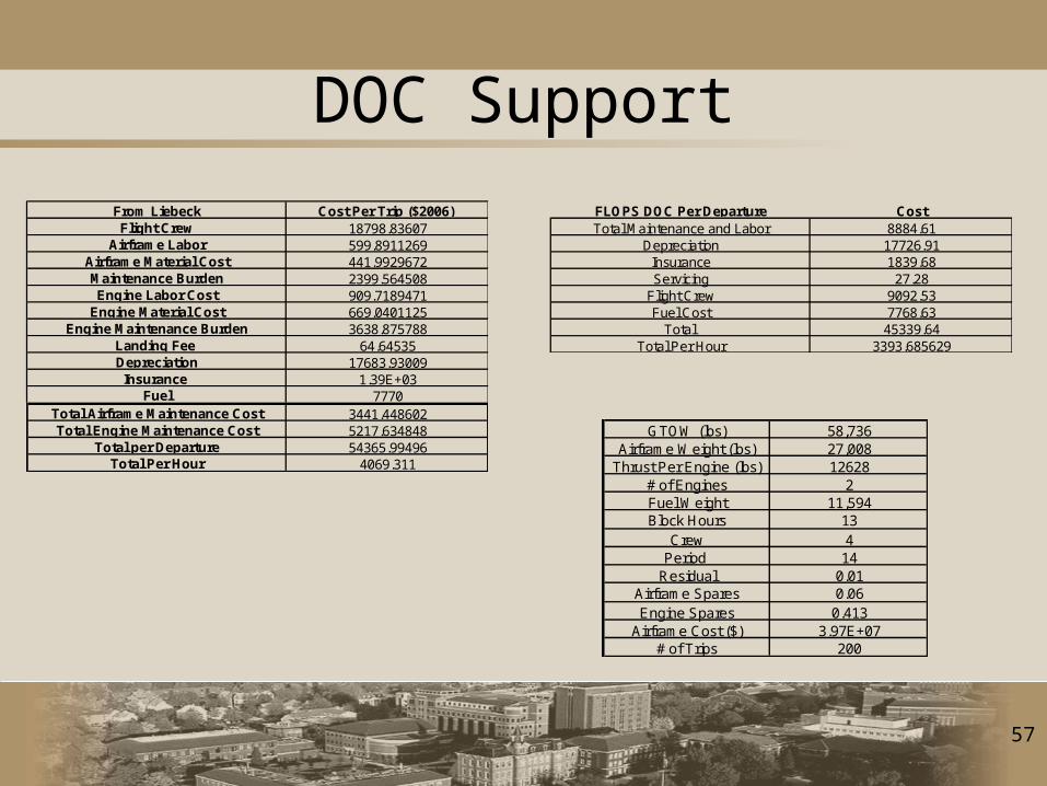
DOC Support
From Liebeck Cost Per Trip ($2006) Flight Crew 18798.83607
Airframe Labor 599.8911269Airframe Material Cost 441.9929672Maintenance Burden 2399.564508Engine Labor Cost 909.7189471
Engine Material Cost 669.0401125Engine Maintenance Burden 3638.875788
Landing Fee 64.64535Depreciation 17683.93009Insurance 1.39E+03
Fuel 7770Total Airframe Maintenance Cost 3441.448602Total Engine Maintenance Cost 5217.634848
Total per Departure 54365.99496Total Per Hour 4069.311
FLOPS DOC Per Departure CostTotal Maintenance and Labor 8884.61
Depreciation 17726.91Insurance 1839.68Servicing 27.28
Flight Crew 9092.53Fuel Cost 7768.63
Total 45339.64Total Per Hour 3393.685629
GTOW (lbs) 58,736Airframe Weight (lbs) 27,008
Thrust Per Engine (lbs) 12628# of Engines 2Fuel Weight 11,594Block Hours 13
Crew 4Period 14
Residual 0.01Airframe Spares 0.06Engine Spares 0.413
Airframe Cost ($) 3.97E+07# of Trips 200
58
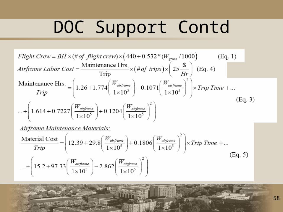
DOC Support Contd

59
DOC Support Contd
60
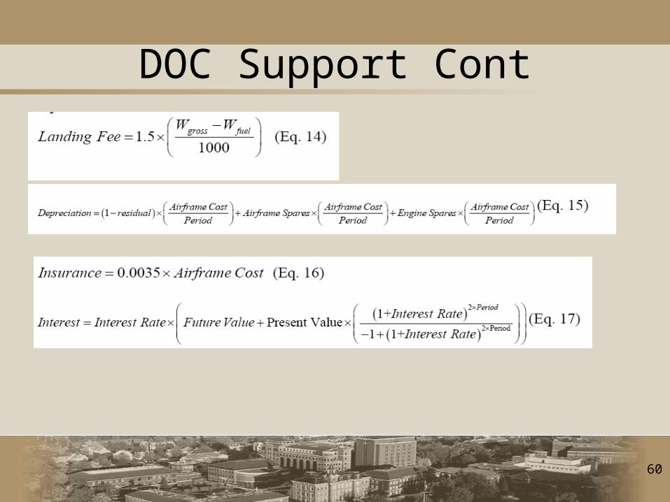
DOC Support Cont