1 cable trays - vergokan · 1 cable trays kbscl60.6 cable tray clickable clicking ends alternative...
TRANSCRIPT
1
CABLE TRAYS 1
1 Cable trays
KBSKBSCLKBSI
KGI/KG NATO
2
CABLE TRAYS1
KbsIKBSI35 Cable tray with interlocking ends 6KBSI60 Cable tray with interlocking ends 7
KbsClKBSCL60 Cable Tray Clickable 8KBSCL60.6Cable Tray Clickable 10
KbsKBS35 Perforated cable tray 11KBS60 Perforated cable tray 12KBS85 Perforated cable tray 13KBS110 Perforated cable tray 14KBS110.6 Perforated cable tray 15
KbsM(I)KBSM(I)60 Cable tray machine constr. interl. ends 16
KGIKGI60 Cable tray not perforated, interlocking 17KGI60S KGI with SIN 18
KGKG110 Cable tray not perforated 19KG110S KG with SIN 20
naTONATO15 Perforated cable tray - upright flanges 21
COVeRD Universal cover 21DZ Cover with swivel clamp 22
COVeR ClaMPsDCO Cover clamp 22DCL Cover clamp clips 22DZK Swivel clamp 23
aCCessORIesB90 Horizontal bend 90° 23DB90 Cover for horizontal bend 90° 24VH Adjustable Corner 24T Horizontal T-piece 25DT Cover for horizontal T-piece 25AS Horizontal adapter 90° 26DAS Cover for horizontal adapter 90° 26KR Cross-over 27DKR Cover for cross-over 27SB90 Rising elbow 90° 28SBCL Snap-in rising elbow 90° 28DSB90 Cover for rising elbow 90° 29VB90 Low elbow 90° 29VBCL Snap-in low elbow 90° 30DVB90 Cover for low elbow 90° 30SDB Hinged joiner double 31DS Hinged joiner 31AZH Universal coupling 90° 32BVSI Stiffening plate 32VS Reducing plate 33E End piece 33RBKBSM Edge protection KBSM(I) 34
MOUnTInG PlaTesMP Folded mounting plate 34MPV Flat mounting plate 34MPVCL Snap-in mounting plate 35
sePeRaTORsSLOS Bolt-in partition 35SLIS Snap-in partition 35CL Clips for SLIS 36
JOInInG PlaTeV15.200 Joining plate 36V35 Joiner for fast mounting 36V60 Joiner for fast mounting 37V85 Joiner for fast mounting 37

3
CABLE TRAYS 1
V35.200 Joining plate 37V60.200 Joining plate 38V85.200 Joining plate 38V110.200 Joiner 38KPW Joiner for wide-span 39LV Supporting corner 39KBV Fast locking for KBSI 39KBVCL Clips locking for KBSCL 40
TECHNICAL INFORMATION 40

4
CABLE TRAYS1
5
CABLE TRAYS 1
6
CABLE TRAYS1
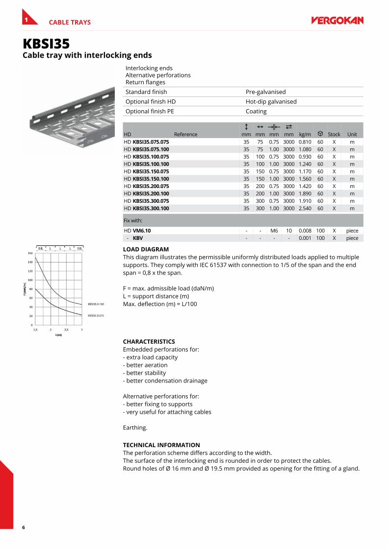
KBSI35Cable tray with interlocking ends
Interlocking ends Alternative perforations Return flanges
Standard finish Pre-galvanised
Optional finish HD Hot-dip galvanised
Optional finish PE Coating
HD ReferenceC
mmN
mmKœL mm
2 mm kg/m u Stock Unit
HD KbsI35.075.075 35 75 0.75 3000 0.810 60 X mHD KbsI35.075.100 35 75 1.00 3000 1.080 60 X mHD KbsI35.100.075 35 100 0.75 3000 0.930 60 X mHD KbsI35.100.100 35 100 1.00 3000 1.240 60 X mHD KbsI35.150.075 35 150 0.75 3000 1.170 60 X mHD KbsI35.150.100 35 150 1.00 3000 1.560 60 X mHD KbsI35.200.075 35 200 0.75 3000 1.420 60 X mHD KbsI35.200.100 35 200 1.00 3000 1.890 60 X mHD KbsI35.300.075 35 300 0.75 3000 1.910 60 X mHD KbsI35.300.100 35 300 1.00 3000 2.540 60 X m
Fix with:
HD VM6.10 - - M6 10 0.008 100 X piece- KbV - - - - 0.001 100 X piece
lOaD DIaGRaM This diagram illustrates the permissible uniformly distributed loads applied to multiple supports. They comply with IEC 61537 with connection to 1/5 of the span and the end span = 0,8 x the span. F = max. admissible load (daN/m) L = support distance (m) Max. deflection (m) = L/100
CHaRaCTeRIsTICs Embedded perforations for: - extra load capacity - better aeration - better stability - better condensation drainage Alternative perforations for: - better fixing to supports - very useful for attaching cables Earthing.
TeCHnICal InfORMaTIOn The perforation scheme differs according to the width. The surface of the interlocking end is rounded in order to protect the cables. Round holes of Ø 16 mm and Ø 19.5 mm provided as opening for the fitting of a gland.
7
CABLE TRAYS 1
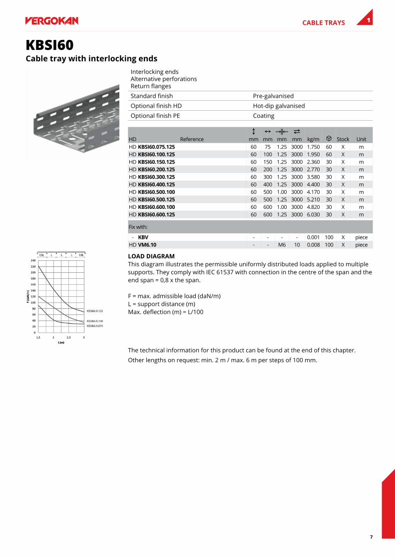
KBSI60Cable tray with interlocking ends
Interlocking ends Alternative perforations Return flanges
Standard finish Pre-galvanised
Optional finish HD Hot-dip galvanised
Optional finish PE Coating
HD ReferenceC
mmN
mmKœL mm
2 mm kg/m u Stock Unit
HD KbsI60.075.125 60 75 1.25 3000 1.750 60 X mHD KbsI60.100.125 60 100 1.25 3000 1.950 60 X mHD KbsI60.150.125 60 150 1.25 3000 2.360 30 X mHD KbsI60.200.125 60 200 1.25 3000 2.770 30 X mHD KbsI60.300.125 60 300 1.25 3000 3.580 30 X mHD KbsI60.400.125 60 400 1.25 3000 4.400 30 X mHD KbsI60.500.100 60 500 1.00 3000 4.170 30 X mHD KbsI60.500.125 60 500 1.25 3000 5.210 30 X mHD KbsI60.600.100 60 600 1.00 3000 4.820 30 X mHD KbsI60.600.125 60 600 1.25 3000 6.030 30 X m
Fix with:
- KbV - - - - 0.001 100 X pieceHD VM6.10 - - M6 10 0.008 100 X piece
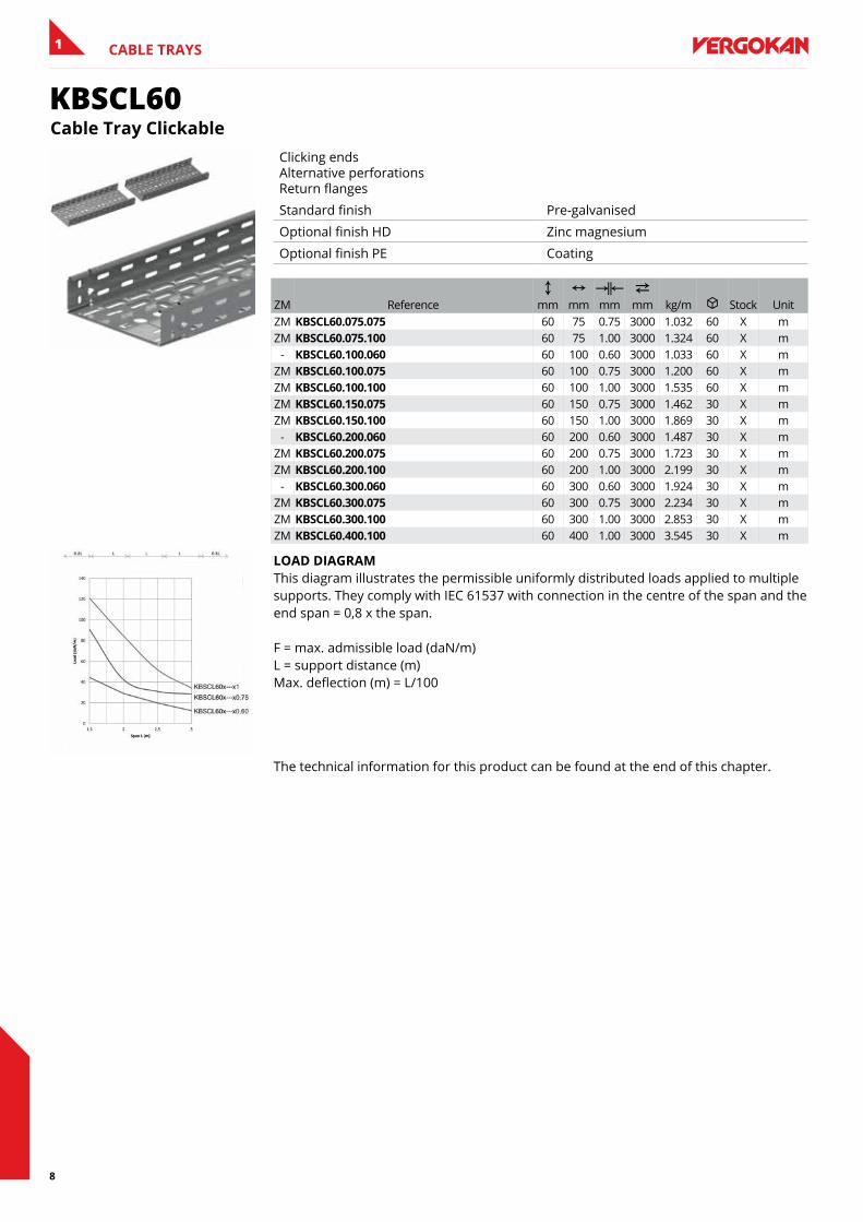
lOaD DIaGRaM This diagram illustrates the permissible uniformly distributed loads applied to multiple supports. They comply with IEC 61537 with connection in the centre of the span and the end span = 0,8 x the span. F = max. admissible load (daN/m) L = support distance (m) Max. deflection (m) = L/100
The technical information for this product can be found at the end of this chapter.
Other lengths on request: min. 2 m / max. 6 m per steps of 100 mm.
8
CABLE TRAYS1
KBSCL60Cable Tray Clickable
Clicking ends Alternative perforations Return flanges
Standard finish Pre-galvanised
Optional finish HD Zinc magnesium
Optional finish PE Coating
ZM ReferenceC
mmN
mmKœL mm
2 mm kg/m u Stock Unit
ZM KbsCl60.075.075 60 75 0.75 3000 1.032 60 X mZM KbsCl60.075.100 60 75 1.00 3000 1.324 60 X m
- KbsCl60.100.060 60 100 0.60 3000 1.033 60 X mZM KbsCl60.100.075 60 100 0.75 3000 1.200 60 X mZM KbsCl60.100.100 60 100 1.00 3000 1.535 60 X mZM KbsCl60.150.075 60 150 0.75 3000 1.462 30 X mZM KbsCl60.150.100 60 150 1.00 3000 1.869 30 X m
- KbsCl60.200.060 60 200 0.60 3000 1.487 30 X mZM KbsCl60.200.075 60 200 0.75 3000 1.723 30 X mZM KbsCl60.200.100 60 200 1.00 3000 2.199 30 X m
- KbsCl60.300.060 60 300 0.60 3000 1.924 30 X mZM KbsCl60.300.075 60 300 0.75 3000 2.234 30 X mZM KbsCl60.300.100 60 300 1.00 3000 2.853 30 X mZM KbsCl60.400.100 60 400 1.00 3000 3.545 30 X m
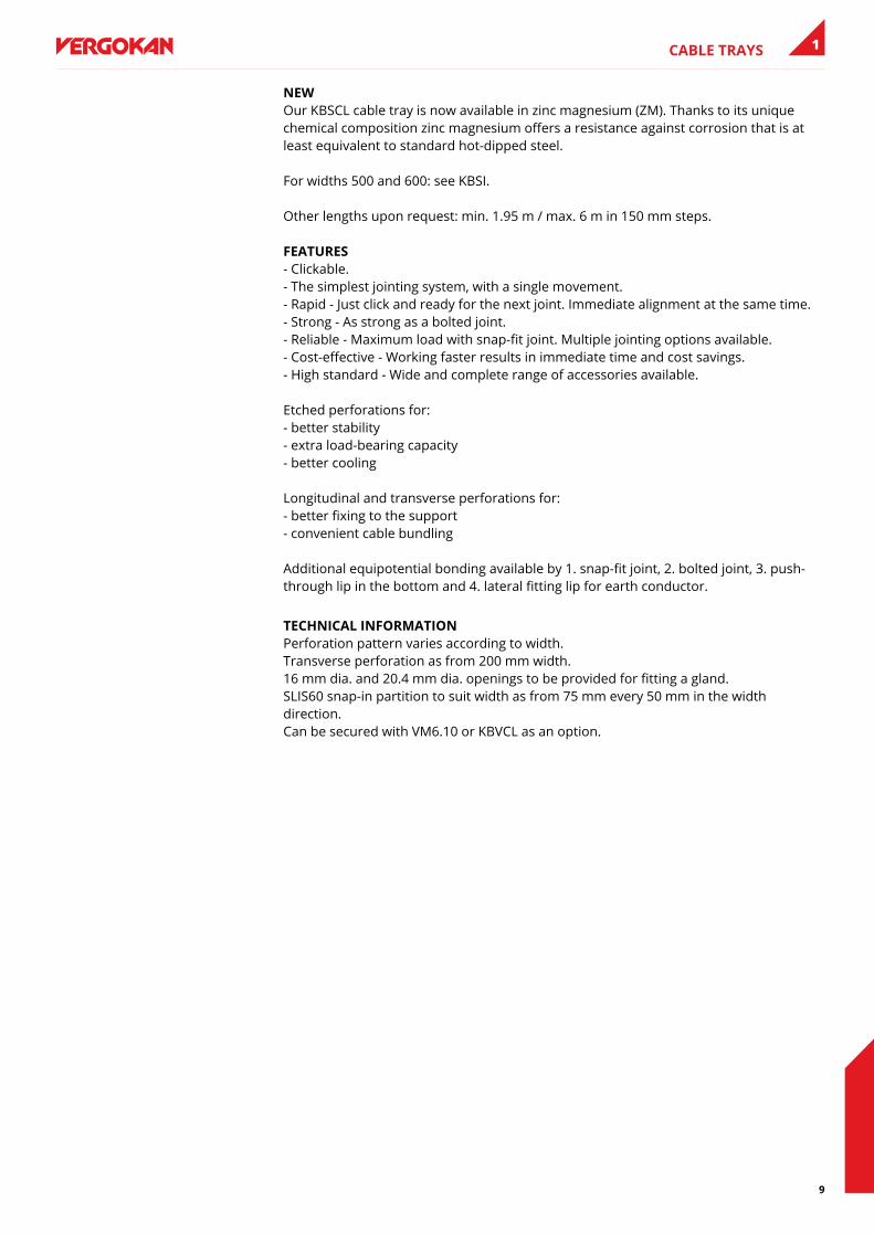
lOaD DIaGRaM This diagram illustrates the permissible uniformly distributed loads applied to multiple supports. They comply with IEC 61537 with connection in the centre of the span and the end span = 0,8 x the span. F = max. admissible load (daN/m) L = support distance (m) Max. deflection (m) = L/100
The technical information for this product can be found at the end of this chapter.
9
CABLE TRAYS 1
neW Our KBSCL cable tray is now available in zinc magnesium (ZM). Thanks to its unique chemical composition zinc magnesium offers a resistance against corrosion that is at least equivalent to standard hot-dipped steel. For widths 500 and 600: see KBSI. Other lengths upon request: min. 1.95 m / max. 6 m in 150 mm steps. feaTURes - Clickable. - The simplest jointing system, with a single movement. - Rapid - Just click and ready for the next joint. Immediate alignment at the same time. - Strong - As strong as a bolted joint. - Reliable - Maximum load with snap-fit joint. Multiple jointing options available. - Cost-effective - Working faster results in immediate time and cost savings. - High standard - Wide and complete range of accessories available. Etched perforations for: - better stability - extra load-bearing capacity - better cooling Longitudinal and transverse perforations for: - better fixing to the support - convenient cable bundling Additional equipotential bonding available by 1. snap-fit joint, 2. bolted joint, 3. push-through lip in the bottom and 4. lateral fitting lip for earth conductor.
TeCHnICal InfORMaTIOn Perforation pattern varies according to width. Transverse perforation as from 200 mm width. 16 mm dia. and 20.4 mm dia. openings to be provided for fitting a gland. SLIS60 snap-in partition to suit width as from 75 mm every 50 mm in the width direction. Can be secured with VM6.10 or KBVCL as an option.
10
CABLE TRAYS1
KBSCL60.6Cable Tray Clickable
Clicking ends Alternative perforations Return flanges
Standard finish Pre-galvanised
Optional finish PE Coating
HD ReferenceC
mmN
mmKœL mm
2 mm kg/m u Stock Unit
- KbsCl60.075.10.6 60 75 1.00 6000 1.328 60 X m- KbsCl60.100.10.6 60 100 1.00 6000 1.511 60 X m- KbsCl60.150.10.6 60 150 1.00 6000 1.890 30 X m- KbsCl60.200.10.6 60 200 1.00 6000 2.112 30 X m- KbsCl60.300.10.6 60 300 1.00 6000 2.829 30 X m- KbsCl60.400.10.6 60 400 1.00 6000 3.399 30 X m
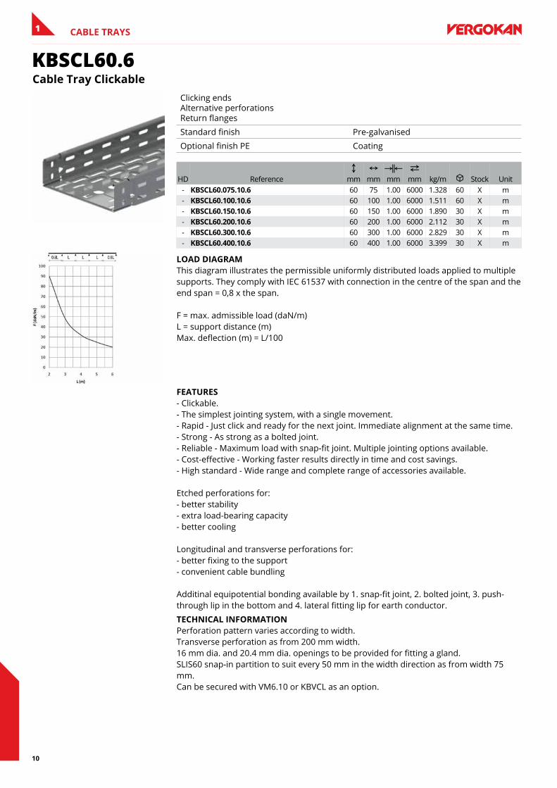
lOaD DIaGRaM This diagram illustrates the permissible uniformly distributed loads applied to multiple supports. They comply with IEC 61537 with connection in the centre of the span and the end span = 0,8 x the span. F = max. admissible load (daN/m) L = support distance (m) Max. deflection (m) = L/100
feaTURes - Clickable. - The simplest jointing system, with a single movement. - Rapid - Just click and ready for the next joint. Immediate alignment at the same time. - Strong - As strong as a bolted joint. - Reliable - Maximum load with snap-fit joint. Multiple jointing options available. - Cost-effective - Working faster results directly in time and cost savings. - High standard - Wide range and complete range of accessories available. Etched perforations for: - better stability - extra load-bearing capacity - better cooling Longitudinal and transverse perforations for: - better fixing to the support - convenient cable bundling Additinal equipotential bonding available by 1. snap-fit joint, 2. bolted joint, 3. push-through lip in the bottom and 4. lateral fitting lip for earth conductor.
TeCHnICal InfORMaTIOn Perforation pattern varies according to width. Transverse perforation as from 200 mm width. 16 mm dia. and 20.4 mm dia. openings to be provided for fitting a gland. SLIS60 snap-in partition to suit every 50 mm in the width direction as from width 75 mm. Can be secured with VM6.10 or KBVCL as an option.
11
CABLE TRAYS 1
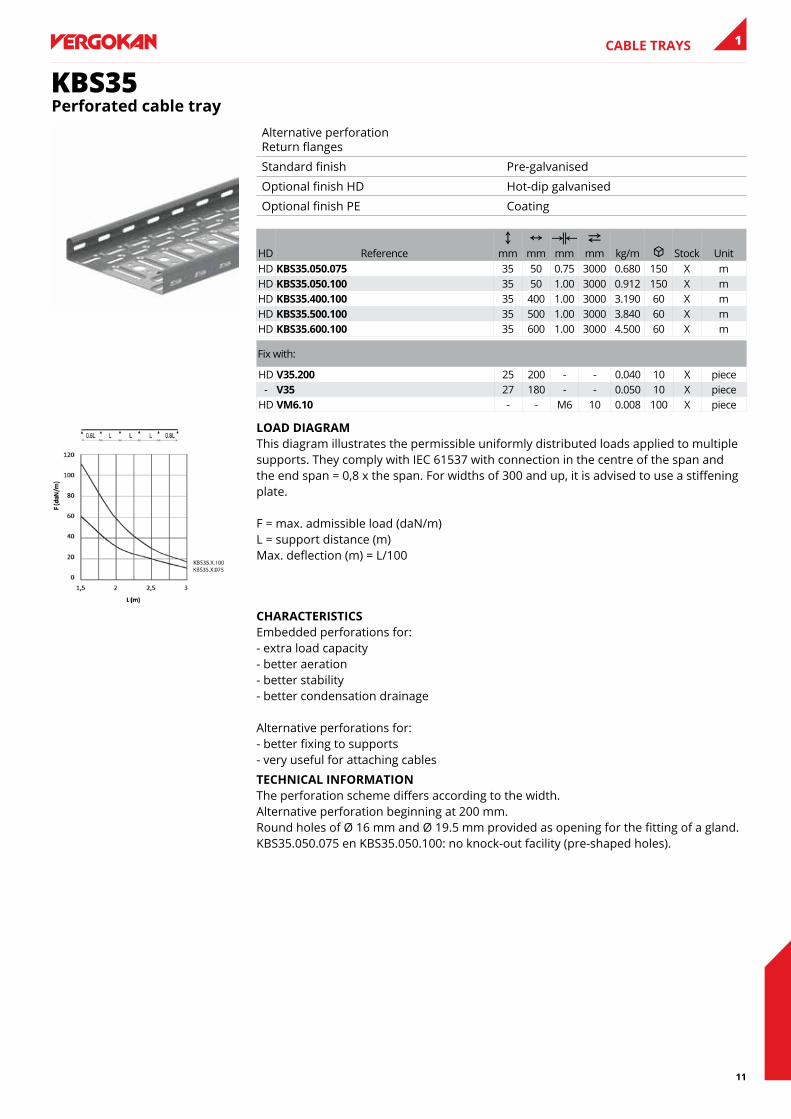
KBS35Perforated cable tray
Alternative perforation Return flanges
Standard finish Pre-galvanised
Optional finish HD Hot-dip galvanised
Optional finish PE Coating
HD ReferenceC
mmN
mmKœL mm
2 mm kg/m u Stock Unit
HD Kbs35.050.075 35 50 0.75 3000 0.680 150 X mHD Kbs35.050.100 35 50 1.00 3000 0.912 150 X mHD Kbs35.400.100 35 400 1.00 3000 3.190 60 X mHD Kbs35.500.100 35 500 1.00 3000 3.840 60 X mHD Kbs35.600.100 35 600 1.00 3000 4.500 60 X m
Fix with:
HD V35.200 25 200 - - 0.040 10 X piece- V35 27 180 - - 0.050 10 X piece
HD VM6.10 - - M6 10 0.008 100 X piece
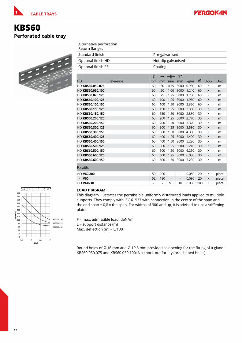
lOaD DIaGRaM This diagram illustrates the permissible uniformly distributed loads applied to multiple supports. They comply with IEC 61537 with connection in the centre of the span and the end span = 0,8 x the span. For widths of 300 and up, it is advised to use a stiffening plate. F = max. admissible load (daN/m) L = support distance (m) Max. deflection (m) = L/100
CHaRaCTeRIsTICs Embedded perforations for: - extra load capacity - better aeration - better stability - better condensation drainage Alternative perforations for: - better fixing to supports - very useful for attaching cables
TeCHnICal InfORMaTIOn The perforation scheme differs according to the width. Alternative perforation beginning at 200 mm. Round holes of Ø 16 mm and Ø 19.5 mm provided as opening for the fitting of a gland. KBS35.050.075 en KBS35.050.100: no knock-out facility (pre-shaped holes).
12
CABLE TRAYS1
KBS60Perforated cable tray
Alternative perforation Return flanges
Standard finish Pre-galvanised
Optional finish HD Hot-dip galvanised
Optional finish PE Coating
HD ReferenceC
mmN
mmKœL mm
2 mm kg/m u Stock Unit
HD Kbs60.050.075 60 50 0.75 3000 0.930 60 X mHD Kbs60.050.100 60 50 1.00 3000 1.240 60 X mHD Kbs60.075.125 60 75 1.25 3000 1.750 60 X mHD Kbs60.100.125 60 100 1.25 3000 1.950 60 X mHD Kbs60.100.150 60 100 1.50 3000 2.350 60 X mHD Kbs60.150.125 60 150 1.25 3000 2.360 30 X mHD Kbs60.150.150 60 150 1.50 3000 2.830 30 X mHD Kbs60.200.125 60 200 1.25 3000 2.770 30 X mHD Kbs60.200.150 60 200 1.50 3000 3.320 30 X mHD Kbs60.300.125 60 300 1.25 3000 3.580 30 X mHD Kbs60.300.150 60 300 1.50 3000 4.300 30 X mHD Kbs60.400.125 60 400 1.25 3000 4.400 30 X mHD Kbs60.400.150 60 400 1.50 3000 5.280 30 X mHD Kbs60.500.125 60 500 1.25 3000 5.210 30 X mHD Kbs60.500.150 60 500 1.50 3000 6.250 30 X mHD Kbs60.600.125 60 600 1.25 3000 6.030 30 X mHD Kbs60.600.150 60 600 1.50 3000 7.230 30 X m
Fix with:
HD V60.200 50 200 - - 0.080 20 X piece- V60 52 180 - - 0.090 20 X piece
HD VM6.10 - - M6 10 0.008 100 X piece
lOaD DIaGRaM This diagram illustrates the permissible uniformly distributed loads applied to multiple supports. They comply with IEC 61537 with connection in the centre of the span and the end span = 0,8 x the span. For widths of 300 and up, it is advised to use a stiffening plate. F = max. admissible load (daN/m) L = support distance (m) Max. deflection (m) = L/100
Round holes of Ø 16 mm and Ø 19.5 mm provided as opening for the fitting of a gland. KBS60.050.075 and KBS60.050.100: No knock-out facility (pre-shaped holes).
13
CABLE TRAYS 1
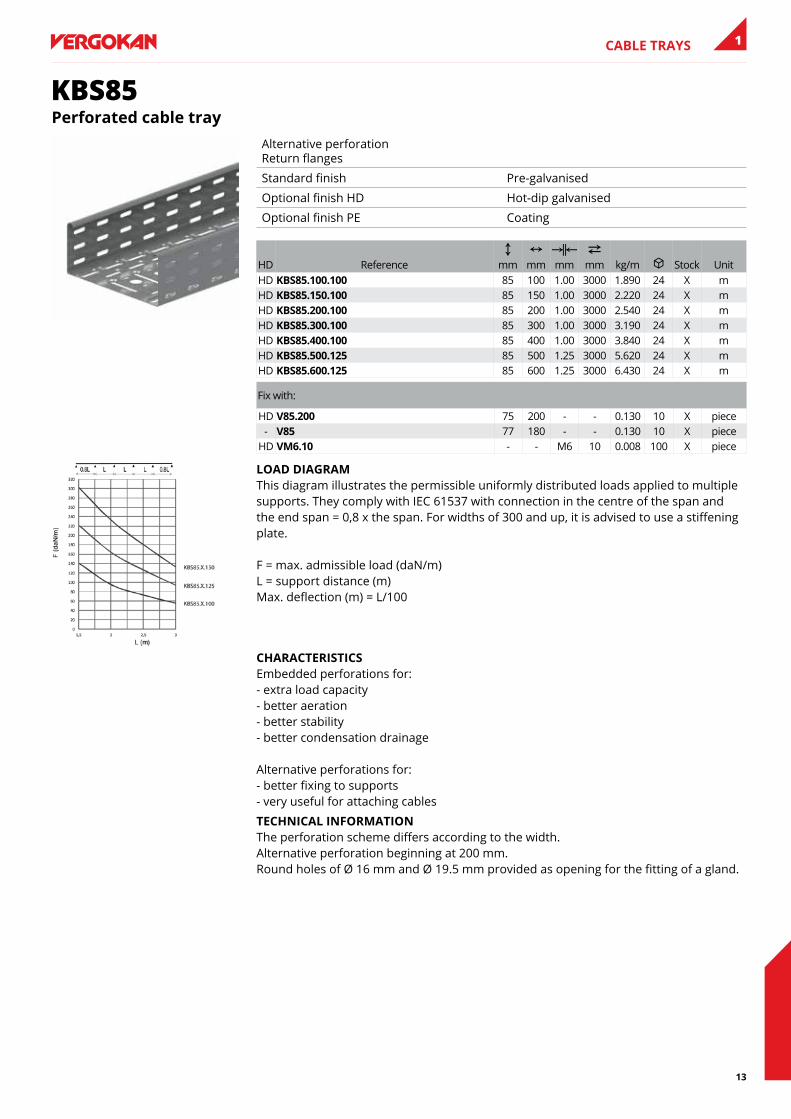
KBS85Perforated cable tray
Alternative perforation Return flanges
Standard finish Pre-galvanised
Optional finish HD Hot-dip galvanised
Optional finish PE Coating
HD ReferenceC
mmN
mmKœL mm
2 mm kg/m u Stock Unit
HD Kbs85.100.100 85 100 1.00 3000 1.890 24 X mHD Kbs85.150.100 85 150 1.00 3000 2.220 24 X mHD Kbs85.200.100 85 200 1.00 3000 2.540 24 X mHD Kbs85.300.100 85 300 1.00 3000 3.190 24 X mHD Kbs85.400.100 85 400 1.00 3000 3.840 24 X mHD Kbs85.500.125 85 500 1.25 3000 5.620 24 X mHD Kbs85.600.125 85 600 1.25 3000 6.430 24 X m
Fix with:
HD V85.200 75 200 - - 0.130 10 X piece- V85 77 180 - - 0.130 10 X piece
HD VM6.10 - - M6 10 0.008 100 X piece
lOaD DIaGRaM This diagram illustrates the permissible uniformly distributed loads applied to multiple supports. They comply with IEC 61537 with connection in the centre of the span and the end span = 0,8 x the span. For widths of 300 and up, it is advised to use a stiffening plate. F = max. admissible load (daN/m) L = support distance (m) Max. deflection (m) = L/100
CHaRaCTeRIsTICs Embedded perforations for: - extra load capacity - better aeration - better stability - better condensation drainage Alternative perforations for: - better fixing to supports - very useful for attaching cables
TeCHnICal InfORMaTIOn The perforation scheme differs according to the width. Alternative perforation beginning at 200 mm. Round holes of Ø 16 mm and Ø 19.5 mm provided as opening for the fitting of a gland.
14
CABLE TRAYS1
KBS110Perforated cable tray
Alternative perforation Return flanges
Standard finish Pre-galvanised
Optional finish HD Hot-dip galvanised
Optional finish PE Coating
HD ReferenceC
mmN
mmKœL mm
2 mm kg/m u Stock Unit
HD Kbs110.150.125 110 150 1.25 3000 3.180 24 X mHD Kbs110.200.125 110 200 1.25 3000 3.580 24 X mHD Kbs110.300.125 110 300 1.25 3000 4.400 24 X mHD Kbs110.400.125 110 400 1.25 3000 5.210 24 X mHD Kbs110.500.125 110 500 1.25 3000 6.030 24 X mHD Kbs110.600.125 110 600 1.25 3000 6.840 24 X m
Fix with:
HD V110.200 100 200 - - 0.170 10 X pieceHD VM6.10 - - M6 10 0.008 100 X pieceHD KPW 115 400 - - 0.590 10 X piece
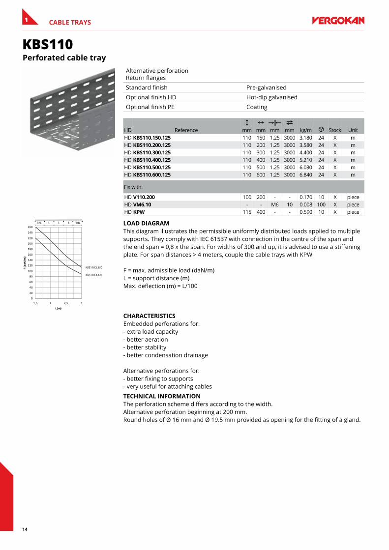
lOaD DIaGRaM This diagram illustrates the permissible uniformly distributed loads applied to multiple supports. They comply with IEC 61537 with connection in the centre of the span and the end span = 0,8 x the span. For widths of 300 and up, it is advised to use a stiffening plate. For span distances > 4 meters, couple the cable trays with KPW F = max. admissible load (daN/m) L = support distance (m) Max. deflection (m) = L/100
CHaRaCTeRIsTICs Embedded perforations for: - extra load capacity - better aeration - better stability - better condensation drainage Alternative perforations for: - better fixing to supports - very useful for attaching cables
TeCHnICal InfORMaTIOn The perforation scheme differs according to the width. Alternative perforation beginning at 200 mm. Round holes of Ø 16 mm and Ø 19.5 mm provided as opening for the fitting of a gland.
15
CABLE TRAYS 1
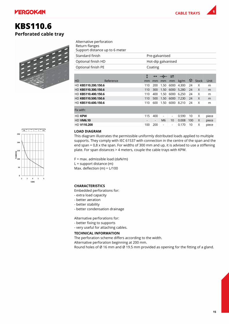
KBS110.6Perforated cable tray
Alternative perforation Return flanges Support distance up to 6 meter
Standard finish Pre-galvanised
Optional finish HD Hot-dip galvanised
Optional finish PE Coating
HD ReferenceC
mmN
mmKœL mm
2 mm kg/m u Stock Unit
HD Kbs110.200.150.6 110 200 1.50 6000 4.300 24 X mHD Kbs110.300.150.6 110 300 1.50 6000 5.280 24 X mHD Kbs110.400.150.6 110 400 1.50 6000 6.250 24 X mHD Kbs110.500.150.6 110 500 1.50 6000 7.230 24 X mHD Kbs110.600.150.6 110 600 1.50 6000 8.210 24 X m
Fix with:
HD KPW 115 400 - - 0.590 10 X pieceHD VM6.10 - - M6 10 0.008 100 X pieceHD V110.200 100 200 - - 0.170 10 X piece
lOaD DIaGRaM This diagram illustrates the permissible uniformly distributed loads applied to multiple supports. They comply with IEC 61537 with connection in the centre of the span and the end span = 0,8 x the span. For widths of 300 mm and up, it is advised to use a stiffening plate. For span distances > 4 meters, couple the cable trays with KPW. F = max. admissible load (daN/m) L = support distance (m) Max. deflection (m) = L/100
CHaRaCTeRIsTICs Embedded perforations for: - extra load capacity - better aeration - better stability - better condensation drainage Alternative perforations for: - better fixing to supports - very useful for attaching cables.
TeCHnICal InfORMaTIOn The perforation scheme differs according to the width. Alternative perforation beginning at 200 mm. Round holes of Ø 16 mm and Ø 19.5 mm provided as opening for the fitting of a gland.
16
CABLE TRAYS1
KBSM(I)60Cable tray machine constr. interl. ends
Can be used with RBKBSM Alternative perforation Return flanges
Standard finish Pre-galvanised
Optional finish PE Coating
HD ReferenceC
mmN
mmKœL mm
2 mm kg/m u Stock Unit
- KbsM60.050.100 60 50 1.00 3000 1.240 3 X m- KbsMI60.075.100 60 75 1.00 3000 1.400 3 X m- KbsMI60.100.100 60 100 1.00 3000 1.560 3 X m- KbsMI60.150.100 60 150 1.00 3000 1.890 3 X m- KbsMI60.200.100 60 200 1.00 3000 2.220 3 X m- KbsMI60.300.100 60 300 1.00 3000 2.870 3 X m
Fix with:
- KbV - - - - 0.001 100 X pieceHD VM6.10 - - M6 10 0.008 100 X piece
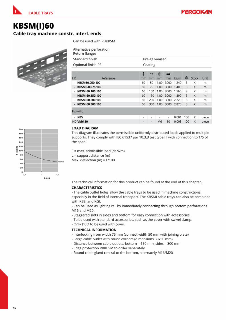
lOaD DIaGRaM This diagram illustrates the permissible uniformly distributed loads applied to multiple supports. They comply with IEC 61537 par 10.3.3 test type III with connection to 1/5 of the span. F = max. admissible load (daN/m) L = support distance (m) Max. deflection (m) = L/100
The technical information for this product can be found at the end of this chapter.
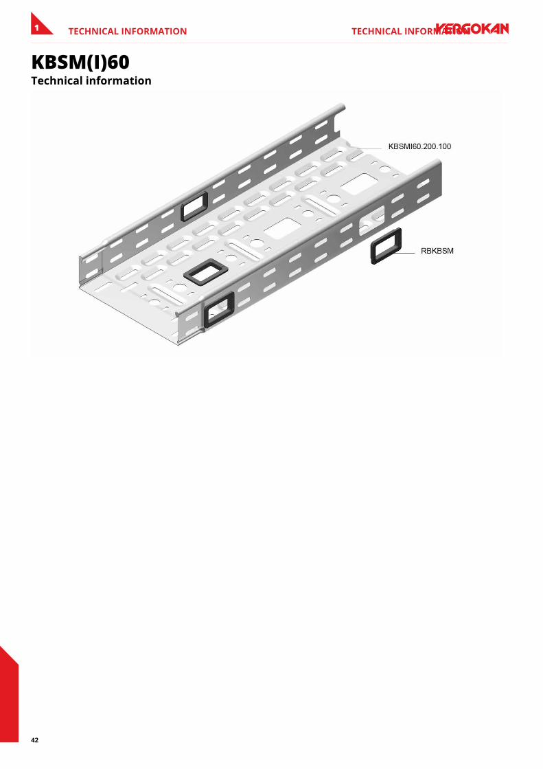
CHaRaCTeRIsTICs - The cable outlet holes allow the cable trays to be used in machine constructions, especially in the field of internal transport. The KBSMI cable trays can also be combined with KBSI and KGI. - Can be used as lighting rail by immediately connecting through bottom perforations M16 and M20. - Staggered slots in sides and bottom for easy connection with accessories. - To be used with standard accessories, such as the cover with swivel clamp. - Only DCO to be used with cover.
TeCHnICal InfORMaTIOn - Interlocking from width 75 mm (connect width 50 mm with joining plate) - Large cable outlet with round corners (dimensions 30x50 mm) - Distance between cable outlets: bottom = 150 mm, sides = 300 mm - Edge protection RBKBSM to order separately - Round cable gland central to the bottom, alternately M16/M20
17
CABLE TRAYS 1
KGI60Cable tray not perforated, interlocking
Not perforated Return flanges
To order Height 35 mm
Standard finish Pre-galvanised
Optional finish HD Hot-dip galvanised
Optional finish PE Coating
HD ReferenceC
mmN
mmKœL mm
2 mm kg/m u Stock Unit
HD KGI60.075.100 60 75 1.00 3000 1.700 3 X mHD KGI60.100.100 60 100 1.00 3000 1.900 3 X mHD KGI60.150.100 60 150 1.00 3000 2.300 3 X mHD KGI60.200.100 60 200 1.00 3000 2.700 3 X mHD KGI60.300.100 60 300 1.00 3000 3.500 3 X m
- KGI60.300.125 60 300 1.25 3000 4.300 3 X mHD KGI60.400.100 60 400 1.00 3000 4.300 3 X m
- KGI60.400.125 60 400 1.25 3000 5.300 3 X m- KGI60.500.125 60 500 1.25 3000 6.300 3 X m- KGI60.600.125 60 600 1.25 3000 7.300 3 X m
Fix with:
- KbV - - - - 0.001 100 X pieceHD VM6.10 - - M6 10 0.008 100 X piece
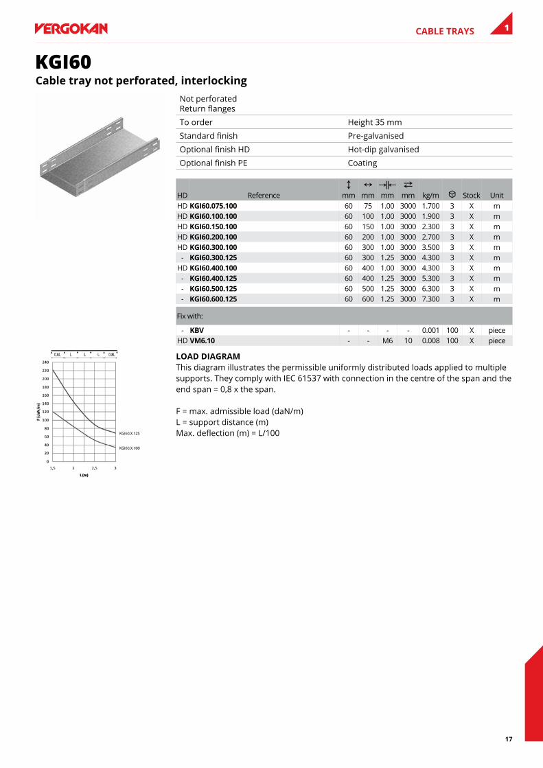
lOaD DIaGRaM This diagram illustrates the permissible uniformly distributed loads applied to multiple supports. They comply with IEC 61537 with connection in the centre of the span and the end span = 0,8 x the span. F = max. admissible load (daN/m) L = support distance (m) Max. deflection (m) = L/100
18
CABLE TRAYS1
KGI60SKGI with sIn
Not perforated Return flanges
To order Height 35 mm
Standard finish Pre-galvanised
Optional finish HD Hot-dip galvanised
Optional finish PE Coating
HD ReferenceC
mmN
mmKœL mm
2 mm kg/m u Stock Unit
HD KGI60.075.100s12 60 75 1.00 3000 2.211 30 mHD KGI60.075.100s13 60 75 1.00 3000 2.211 30 mHD KGI60.075.100s23 60 75 1.00 3000 2.722 30 mHD KGI60.100.100s12 60 100 1.00 3000 2.411 30 mHD KGI60.100.100s13 60 100 1.00 3000 2.411 30 mHD KGI60.100.100s23 60 100 1.00 3000 2.922 30 mHD KGI60.150.100s12 60 150 1.00 3000 2.811 30 mHD KGI60.150.100s13 60 150 1.00 3000 2.811 30 mHD KGI60.150.100s23 60 150 1.00 3000 3.322 30 mHD KGI60.200.100s12 60 200 1.00 3000 3.211 30 mHD KGI60.200.100s13 60 200 1.00 3000 3.211 30 mHD KGI60.200.100s23 60 200 1.00 3000 3.722 30 mHD KGI60.300.100s12 60 300 1.00 3000 4.011 30 mHD KGI60.300.100s13 60 300 1.00 3000 4.011 30 mHD KGI60.300.100s23 60 300 1.00 3000 4.522 30 m
- KGI60.300.125s12 60 300 1.25 3000 4.811 30 m- KGI60.300.125s13 60 300 1.25 3000 4.811 30 m- KGI60.300.125s23 60 300 1.25 3000 5.322 30 m
HD KGI60.400.100s12 60 400 1.00 3000 4.811 30 mHD KGI60.400.100s13 60 400 1.00 3000 4.811 30 mHD KGI60.400.100s23 60 400 1.00 3000 5.322 30 m
- KGI60.400.125s12 60 400 1.25 3000 5.811 30 m- KGI60.400.125s13 60 400 1.25 3000 5.811 30 m- KGI60.400.125s23 60 400 1.25 3000 6.322 30 m- KGI60.500.125s12 60 500 1.25 3000 6.811 30 m- KGI60.500.125s13 60 500 1.25 3000 6.811 30 m- KGI60.500.125s23 60 500 1.25 3000 7.322 30 m- KGI60.600.125s12 60 600 1.25 3000 7.811 30 m- KGI60.600.125s13 60 600 1.25 3000 7.811 30 m- KGI60.600.125s23 60 600 1.25 3000 8.322 30 m
- KbV - - - - 0.001 100 X pieceHD VM6.10 - - M6 10 0.008 100 X piece
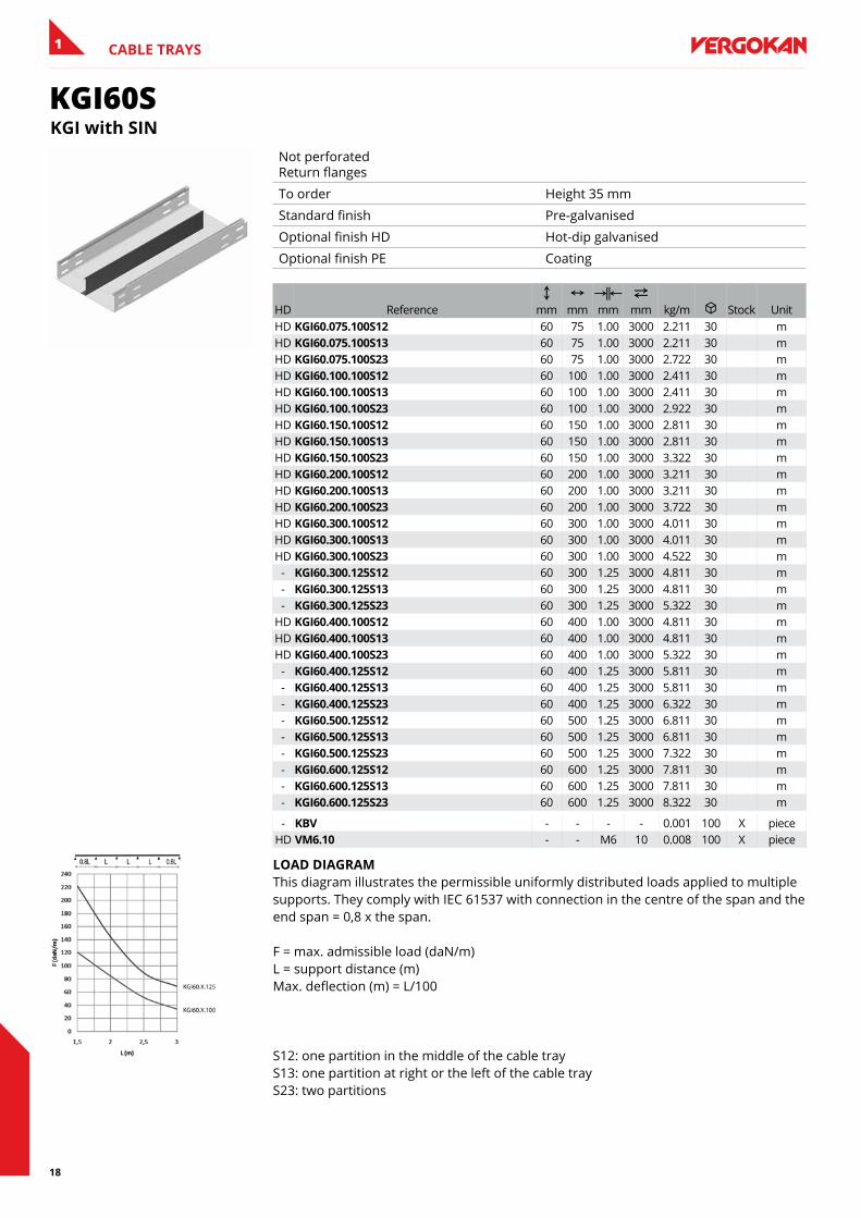
lOaD DIaGRaM This diagram illustrates the permissible uniformly distributed loads applied to multiple supports. They comply with IEC 61537 with connection in the centre of the span and the end span = 0,8 x the span. F = max. admissible load (daN/m) L = support distance (m) Max. deflection (m) = L/100 S12: one partition in the middle of the cable tray S13: one partition at right or the left of the cable tray S23: two partitions
19
CABLE TRAYS 1
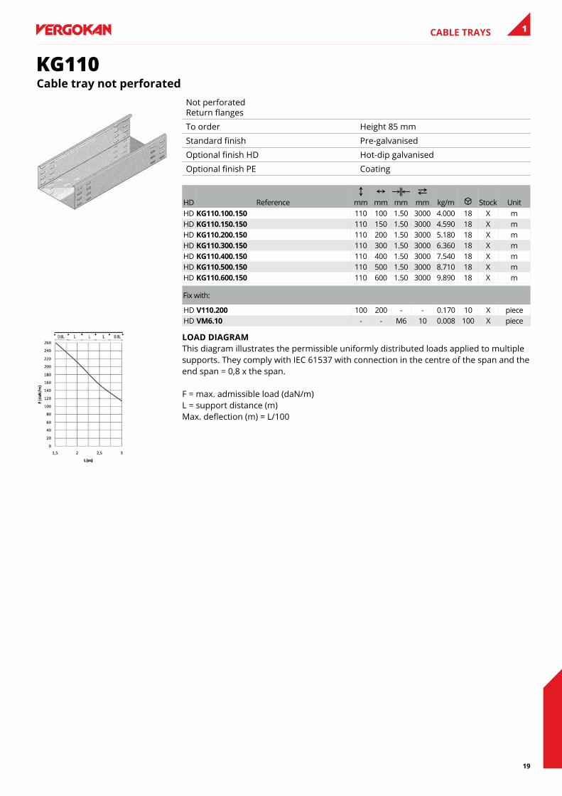
KG110Cable tray not perforated
Not perforated Return flanges
To order Height 85 mm
Standard finish Pre-galvanised
Optional finish HD Hot-dip galvanised
Optional finish PE Coating
HD ReferenceC
mmN
mmKœL mm
2 mm kg/m u Stock Unit
HD KG110.100.150 110 100 1.50 3000 4.000 18 X mHD KG110.150.150 110 150 1.50 3000 4.590 18 X mHD KG110.200.150 110 200 1.50 3000 5.180 18 X mHD KG110.300.150 110 300 1.50 3000 6.360 18 X mHD KG110.400.150 110 400 1.50 3000 7.540 18 X mHD KG110.500.150 110 500 1.50 3000 8.710 18 X mHD KG110.600.150 110 600 1.50 3000 9.890 18 X m
Fix with:
HD V110.200 100 200 - - 0.170 10 X pieceHD VM6.10 - - M6 10 0.008 100 X piece
lOaD DIaGRaM This diagram illustrates the permissible uniformly distributed loads applied to multiple supports. They comply with IEC 61537 with connection in the centre of the span and the end span = 0,8 x the span. F = max. admissible load (daN/m) L = support distance (m) Max. deflection (m) = L/100
20
CABLE TRAYS1
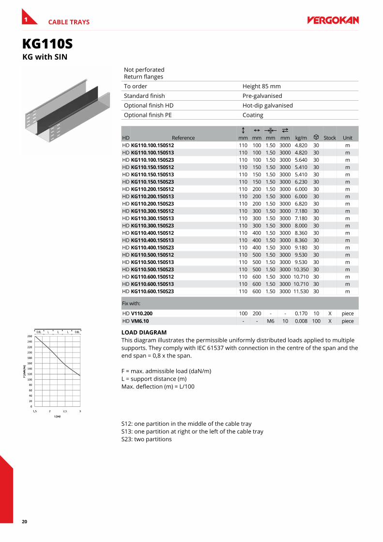
KG110SKG with sIn
Not perforated Return flanges
To order Height 85 mm
Standard finish Pre-galvanised
Optional finish HD Hot-dip galvanised
Optional finish PE Coating
HD ReferenceC
mmN
mmKœL mm
2 mm kg/m u Stock Unit
HD KG110.100.150s12 110 100 1.50 3000 4.820 30 mHD KG110.100.150s13 110 100 1.50 3000 4.820 30 mHD KG110.100.150s23 110 100 1.50 3000 5.640 30 mHD KG110.150.150s12 110 150 1.50 3000 5.410 30 mHD KG110.150.150s13 110 150 1.50 3000 5.410 30 mHD KG110.150.150s23 110 150 1.50 3000 6.230 30 mHD KG110.200.150s12 110 200 1.50 3000 6.000 30 mHD KG110.200.150s13 110 200 1.50 3000 6.000 30 mHD KG110.200.150s23 110 200 1.50 3000 6.820 30 mHD KG110.300.150s12 110 300 1.50 3000 7.180 30 mHD KG110.300.150s13 110 300 1.50 3000 7.180 30 mHD KG110.300.150s23 110 300 1.50 3000 8.000 30 mHD KG110.400.150s12 110 400 1.50 3000 8.360 30 mHD KG110.400.150s13 110 400 1.50 3000 8.360 30 mHD KG110.400.150s23 110 400 1.50 3000 9.180 30 mHD KG110.500.150s12 110 500 1.50 3000 9.530 30 mHD KG110.500.150s13 110 500 1.50 3000 9.530 30 mHD KG110.500.150s23 110 500 1.50 3000 10.350 30 mHD KG110.600.150s12 110 600 1.50 3000 10.710 30 mHD KG110.600.150s13 110 600 1.50 3000 10.710 30 mHD KG110.600.150s23 110 600 1.50 3000 11.530 30 m
Fix with:
HD V110.200 100 200 - - 0.170 10 X pieceHD VM6.10 - - M6 10 0.008 100 X piece
lOaD DIaGRaM This diagram illustrates the permissible uniformly distributed loads applied to multiple supports. They comply with IEC 61537 with connection in the centre of the span and the end span = 0,8 x the span. F = max. admissible load (daN/m) L = support distance (m) Max. deflection (m) = L/100
S12: one partition in the middle of the cable tray S13: one partition at right or the left of the cable tray S23: two partitions
21
CABLE TRAYS 1
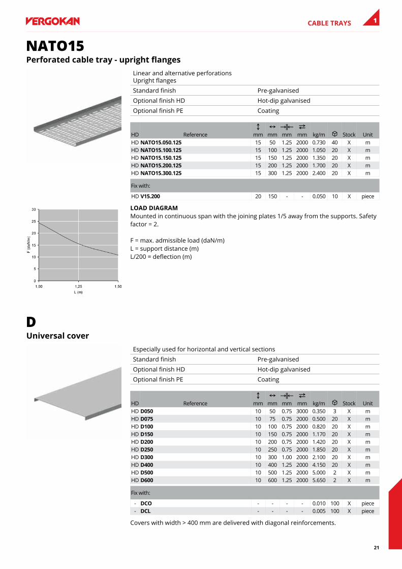
NATO15Perforated cable tray - upright flanges
Linear and alternative perforations Upright flanges
Standard finish Pre-galvanised
Optional finish HD Hot-dip galvanised
Optional finish PE Coating
HD ReferenceC
mmN
mmKœL mm
2 mm kg/m u Stock Unit
HD naTO15.050.125 15 50 1.25 2000 0.730 40 X mHD naTO15.100.125 15 100 1.25 2000 1.050 20 X mHD naTO15.150.125 15 150 1.25 2000 1.350 20 X mHD naTO15.200.125 15 200 1.25 2000 1.700 20 X mHD naTO15.300.125 15 300 1.25 2000 2.400 20 X m
Fix with:
HD V15.200 20 150 - - 0.050 10 X piece
lOaD DIaGRaM Mounted in continuous span with the joining plates 1/5 away from the supports. Safety factor = 2. F = max. admissible load (daN/m) L = support distance (m) L/200 = deflection (m)
DUniversal cover
Especially used for horizontal and vertical sections
Standard finish Pre-galvanised
Optional finish HD Hot-dip galvanised
Optional finish PE Coating
HD ReferenceC
mmN
mmKœL mm
2 mm kg/m u Stock Unit
HD D050 10 50 0.75 3000 0.350 3 X mHD D075 10 75 0.75 2000 0.500 20 X mHD D100 10 100 0.75 2000 0.820 20 X mHD D150 10 150 0.75 2000 1.170 20 X mHD D200 10 200 0.75 2000 1.420 20 X mHD D250 10 250 0.75 2000 1.850 20 X mHD D300 10 300 1.00 2000 2.100 20 X mHD D400 10 400 1.25 2000 4.150 20 X mHD D500 10 500 1.25 2000 5.000 2 X mHD D600 10 600 1.25 2000 5.650 2 X m
Fix with:
- DCO - - - - 0.010 100 X piece- DCl - - - - 0.005 100 X piece
Covers with width > 400 mm are delivered with diagonal reinforcements.
22
CABLE TRAYS1
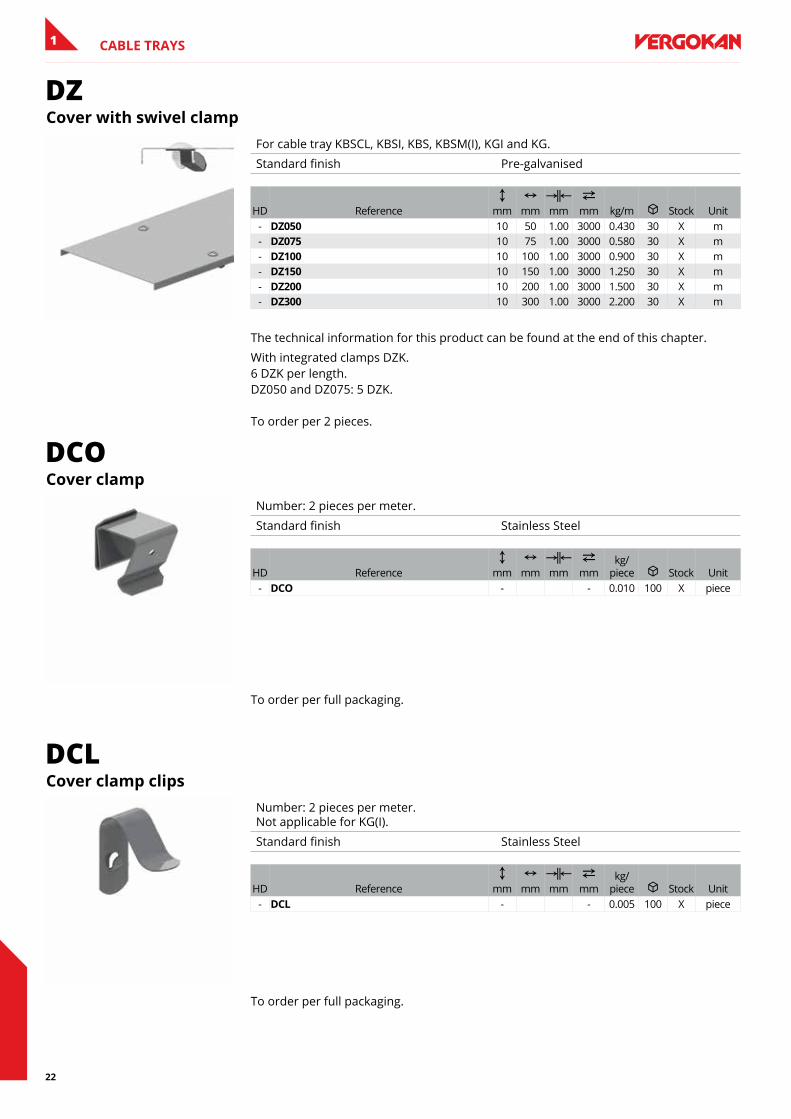
DZCover with swivel clamp
For cable tray KBSCL, KBSI, KBS, KBSM(I), KGI and KG.
Standard finish Pre-galvanised
HD ReferenceC
mmN
mmKœL mm
2 mm kg/m u Stock Unit
- DZ050 10 50 1.00 3000 0.430 30 X m- DZ075 10 75 1.00 3000 0.580 30 X m- DZ100 10 100 1.00 3000 0.900 30 X m- DZ150 10 150 1.00 3000 1.250 30 X m- DZ200 10 200 1.00 3000 1.500 30 X m- DZ300 10 300 1.00 3000 2.200 30 X m
The technical information for this product can be found at the end of this chapter.
With integrated clamps DZK. 6 DZK per length. DZ050 and DZ075: 5 DZK. To order per 2 pieces.
DCOCover clamp
Number: 2 pieces per meter.
Standard finish Stainless Steel
HD ReferenceC
mmN
mmKœL mm
2 mm
kg/piece u Stock Unit
- DCO - - 0.010 100 X piece
To order per full packaging.
DCLCover clamp clips
Number: 2 pieces per meter. Not applicable for KG(I).
Standard finish Stainless Steel
HD ReferenceC
mmN
mmKœL mm
2 mm
kg/piece u Stock Unit
- DCl - - 0.005 100 X piece
To order per full packaging.
23
CABLE TRAYS 1
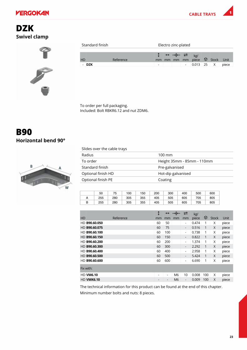
DZKswivel clamp
Standard finish Electro zinc-plated
HD ReferenceC
mmN
mmKœL mm
2 mm
kg/piece u Stock Unit
- DZK - - 0.013 25 X piece
To order per full packaging. Included: Bolt RBKR6.12 and nut ZDM6.
B90Horizontal bend 90°
Slides over the cable trays
Radius 100 mm
To order Height 35mm - 85mm - 110mm
Standard finish Pre-galvanised
Optional finish HD Hot-dip galvanised
Optional finish PE Coating
50 75 100 150 200 300 400 500 600A 255 280 305 355 405 505 605 705 805B 255 280 305 355 405 505 605 705 805
HD ReferenceC
mmN
mmKœL mm
2 mm
kg/piece u Stock Unit
HD b90.60.050 60 50 - 0.474 1 X pieceHD b90.60.075 60 75 - 0.516 1 X pieceHD b90.60.100 60 100 - 0.738 1 X pieceHD b90.60.150 60 150 - 0.822 1 X pieceHD b90.60.200 60 200 - 1.374 1 X pieceHD b90.60.300 60 300 - 2.292 1 X pieceHD b90.60.400 60 400 - 2.958 1 X pieceHD b90.60.500 60 500 - 5.424 1 X pieceHD b90.60.600 60 600 - 6.690 1 X piece
Fix with:
HD VM6.10 - - M6 10 0.008 100 X pieceHD VMK6.10 - - M6 - 0.009 100 X piece
The technical information for this product can be found at the end of this chapter.
Minimum number bolts and nuts: 8 pieces.

24
CABLE TRAYS1
DB90Cover for horizontal bend 90°
Standard finish Pre-galvanised
Optional finish HD Hot-dip galvanised
Optional finish PE Coating
50 75 100 150 200 300 400 500 600B 256 281 306 356 406 506 606 706 806
HD ReferenceC
mmN
mmKœL mm
2 mm
kg/piece u Stock Unit
HD Db90.050 10 56 - 0.269 1 X pieceHD Db90.075 10 81 - 0.378 1 X pieceHD Db90.100 10 106 - 0.497 1 X pieceHD Db90.150 10 156 - 0.766 1 X pieceHD Db90.200 10 206 - 1.073 1 X pieceHD Db90.300 10 306 - 1.806 1 X pieceHD Db90.400 10 406 - 2.630 1 X pieceHD Db90.500 10 506 - 3.662 1 X pieceHD Db90.600 10 606 - 4.851 1 X piece
Fix with:
- DCl - - - - 0.005 100 X piece
VHadjustable Corner
Corner plate adjustable between 90° and 180°
To order Height 35 mm - 85 mm - 110 mm
Standard finish Pre-galvanised
Optional finish HD Hot-dip galvanised
Optional finish PE Coating
HD ReferenceC
mmN
mmKœL mm
2 mm
kg/piece u Stock Unit
HD VH60.050 60 50 - 0.448 1 pieceHD VH60.075 60 75 - 0.486 1 X pieceHD VH60.100 60 100 - 0.533 1 X pieceHD VH60.150 60 150 - 0.659 1 X pieceHD VH60.200 60 200 - 0.824 1 X pieceHD VH60.300 60 300 - 1.385 1 X pieceHD VH60.400 60 400 - 2.042 1 X pieceHD VH60.500 60 500 - 2.913 1 X pieceHD VH60.600 60 600 - 3.938 1 X piece
Fix with:
HD VM6.10 - - M6 10 0.008 100 X pieceHD VMK6.10 - - M6 - 0.009 100 X piece
Minimum number bolts and nuts: 4 pieces.
25
CABLE TRAYS 1
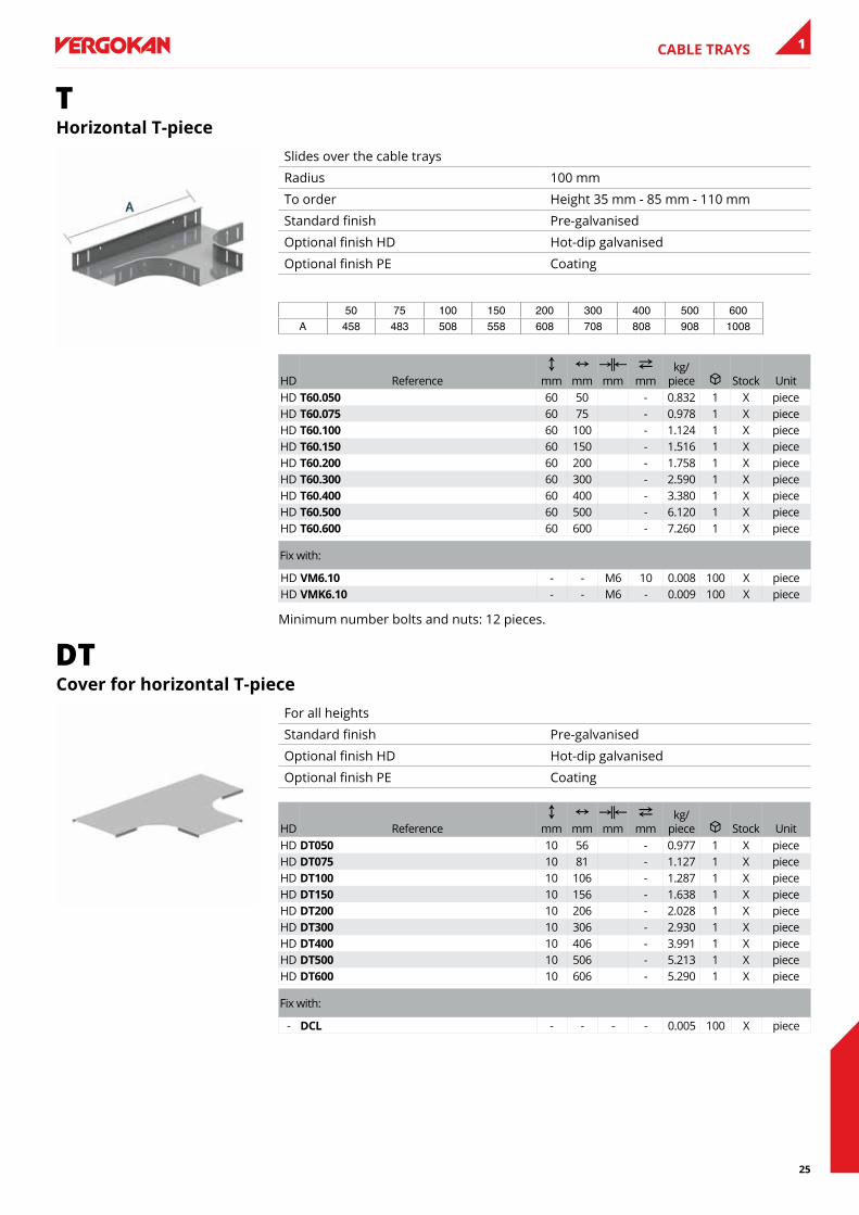
THorizontal T-piece
Slides over the cable trays
Radius 100 mm
To order Height 35 mm - 85 mm - 110 mm
Standard finish Pre-galvanised
Optional finish HD Hot-dip galvanised
Optional finish PE Coating
50 75 100 150 200 300 400 500 600A 458 483 508 558 608 708 808 908 1008
HD ReferenceC
mmN
mmKœL mm
2 mm
kg/piece u Stock Unit
HD T60.050 60 50 - 0.832 1 X pieceHD T60.075 60 75 - 0.978 1 X pieceHD T60.100 60 100 - 1.124 1 X pieceHD T60.150 60 150 - 1.516 1 X pieceHD T60.200 60 200 - 1.758 1 X pieceHD T60.300 60 300 - 2.590 1 X pieceHD T60.400 60 400 - 3.380 1 X pieceHD T60.500 60 500 - 6.120 1 X pieceHD T60.600 60 600 - 7.260 1 X piece
Fix with:
HD VM6.10 - - M6 10 0.008 100 X pieceHD VMK6.10 - - M6 - 0.009 100 X piece
Minimum number bolts and nuts: 12 pieces.
DTCover for horizontal T-piece
For all heights
Standard finish Pre-galvanised
Optional finish HD Hot-dip galvanised
Optional finish PE Coating
HD ReferenceC
mmN
mmKœL mm
2 mm
kg/piece u Stock Unit
HD DT050 10 56 - 0.977 1 X pieceHD DT075 10 81 - 1.127 1 X pieceHD DT100 10 106 - 1.287 1 X pieceHD DT150 10 156 - 1.638 1 X pieceHD DT200 10 206 - 2.028 1 X pieceHD DT300 10 306 - 2.930 1 X pieceHD DT400 10 406 - 3.991 1 X pieceHD DT500 10 506 - 5.213 1 X pieceHD DT600 10 606 - 5.290 1 X piece
Fix with:
- DCl - - - - 0.005 100 X piece
26
CABLE TRAYS1
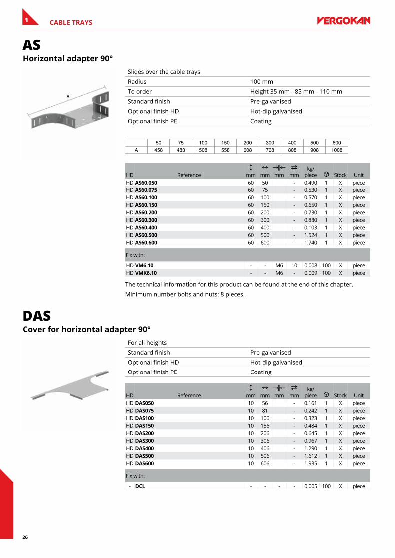
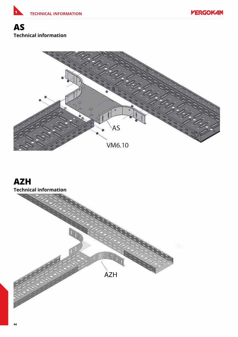
ASHorizontal adapter 90°
Slides over the cable trays
Radius 100 mm
To order Height 35 mm - 85 mm - 110 mm
Standard finish Pre-galvanised
Optional finish HD Hot-dip galvanised
Optional finish PE Coating
50 75 100 150 200 300 400 500 600A 458 483 508 558 608 708 808 908 1008
HD ReferenceC
mmN
mmKœL mm
2 mm
kg/piece u Stock Unit
HD as60.050 60 50 - 0.490 1 X pieceHD as60.075 60 75 - 0.530 1 X pieceHD as60.100 60 100 - 0.570 1 X pieceHD as60.150 60 150 - 0.650 1 X pieceHD as60.200 60 200 - 0.730 1 X pieceHD as60.300 60 300 - 0.880 1 X pieceHD as60.400 60 400 - 0.103 1 X pieceHD as60.500 60 500 - 1.524 1 X pieceHD as60.600 60 600 - 1.740 1 X piece
Fix with:
HD VM6.10 - - M6 10 0.008 100 X pieceHD VMK6.10 - - M6 - 0.009 100 X piece
The technical information for this product can be found at the end of this chapter.
Minimum number bolts and nuts: 8 pieces.
DASCover for horizontal adapter 90°
For all heights
Standard finish Pre-galvanised
Optional finish HD Hot-dip galvanised
Optional finish PE Coating
HD ReferenceC
mmN
mmKœL mm
2 mm
kg/piece u Stock Unit
HD Das050 10 56 - 0.161 1 X pieceHD Das075 10 81 - 0.242 1 X pieceHD Das100 10 106 - 0.323 1 X pieceHD Das150 10 156 - 0.484 1 X pieceHD Das200 10 206 - 0.645 1 X pieceHD Das300 10 306 - 0.967 1 X pieceHD Das400 10 406 - 1.290 1 X pieceHD Das500 10 506 - 1.612 1 X pieceHD Das600 10 606 - 1.935 1 X piece
Fix with:
- DCl - - - - 0.005 100 X piece
27
CABLE TRAYS 1
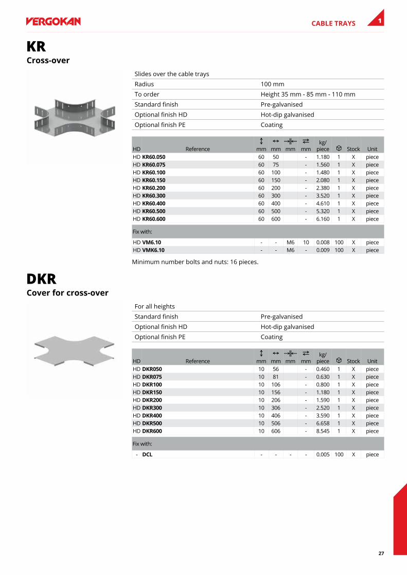
KRCross-over
Slides over the cable trays
Radius 100 mm
To order Height 35 mm - 85 mm - 110 mm
Standard finish Pre-galvanised
Optional finish HD Hot-dip galvanised
Optional finish PE Coating
HD ReferenceC
mmN
mmKœL mm
2 mm
kg/piece u Stock Unit
HD KR60.050 60 50 - 1.180 1 X pieceHD KR60.075 60 75 - 1.560 1 X pieceHD KR60.100 60 100 - 1.480 1 X pieceHD KR60.150 60 150 - 2.080 1 X pieceHD KR60.200 60 200 - 2.380 1 X pieceHD KR60.300 60 300 - 3.520 1 X pieceHD KR60.400 60 400 - 4.610 1 X pieceHD KR60.500 60 500 - 5.320 1 X pieceHD KR60.600 60 600 - 6.160 1 X piece
Fix with:
HD VM6.10 - - M6 10 0.008 100 X pieceHD VMK6.10 - - M6 - 0.009 100 X piece
Minimum number bolts and nuts: 16 pieces.
DKRCover for cross-over
For all heights
Standard finish Pre-galvanised
Optional finish HD Hot-dip galvanised
Optional finish PE Coating
HD ReferenceC
mmN
mmKœL mm
2 mm
kg/piece u Stock Unit
HD DKR050 10 56 - 0.460 1 X pieceHD DKR075 10 81 - 0.630 1 X pieceHD DKR100 10 106 - 0.800 1 X pieceHD DKR150 10 156 - 1.180 1 X pieceHD DKR200 10 206 - 1.590 1 X pieceHD DKR300 10 306 - 2.520 1 X pieceHD DKR400 10 406 - 3.590 1 X pieceHD DKR500 10 506 - 6.658 1 X pieceHD DKR600 10 606 - 8.545 1 X piece
Fix with:
- DCl - - - - 0.005 100 X piece
28
CABLE TRAYS1
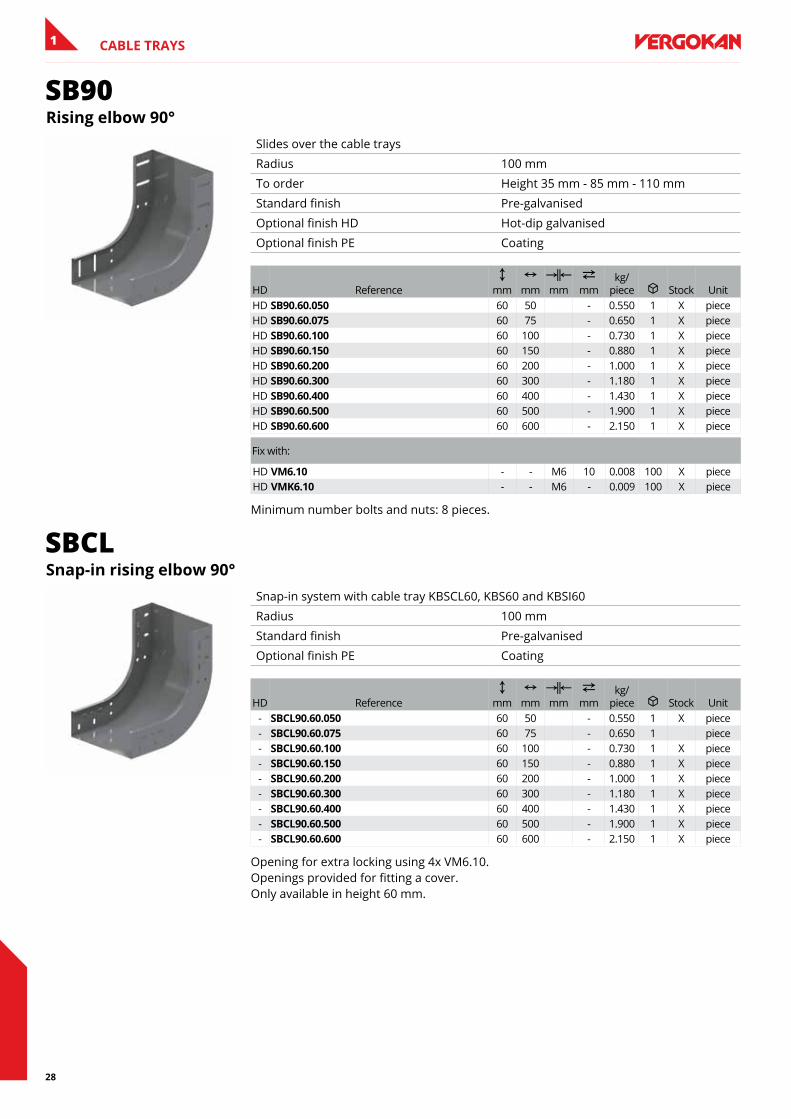
SB90Rising elbow 90°
Slides over the cable trays
Radius 100 mm
To order Height 35 mm - 85 mm - 110 mm
Standard finish Pre-galvanised
Optional finish HD Hot-dip galvanised
Optional finish PE Coating
HD ReferenceC
mmN
mmKœL mm
2 mm
kg/piece u Stock Unit
HD sb90.60.050 60 50 - 0.550 1 X pieceHD sb90.60.075 60 75 - 0.650 1 X pieceHD sb90.60.100 60 100 - 0.730 1 X pieceHD sb90.60.150 60 150 - 0.880 1 X pieceHD sb90.60.200 60 200 - 1.000 1 X pieceHD sb90.60.300 60 300 - 1.180 1 X pieceHD sb90.60.400 60 400 - 1.430 1 X pieceHD sb90.60.500 60 500 - 1.900 1 X pieceHD sb90.60.600 60 600 - 2.150 1 X piece
Fix with:
HD VM6.10 - - M6 10 0.008 100 X pieceHD VMK6.10 - - M6 - 0.009 100 X piece
Minimum number bolts and nuts: 8 pieces.
SBCLsnap-in rising elbow 90°
Snap-in system with cable tray KBSCL60, KBS60 and KBSI60
Radius 100 mm
Standard finish Pre-galvanised
Optional finish PE Coating
HD ReferenceC
mmN
mmKœL mm
2 mm
kg/piece u Stock Unit
- sbCl90.60.050 60 50 - 0.550 1 X piece- sbCl90.60.075 60 75 - 0.650 1 piece- sbCl90.60.100 60 100 - 0.730 1 X piece- sbCl90.60.150 60 150 - 0.880 1 X piece- sbCl90.60.200 60 200 - 1.000 1 X piece- sbCl90.60.300 60 300 - 1.180 1 X piece- sbCl90.60.400 60 400 - 1.430 1 X piece- sbCl90.60.500 60 500 - 1.900 1 X piece- sbCl90.60.600 60 600 - 2.150 1 X piece
Opening for extra locking using 4x VM6.10. Openings provided for fitting a cover. Only available in height 60 mm.
29
CABLE TRAYS 1
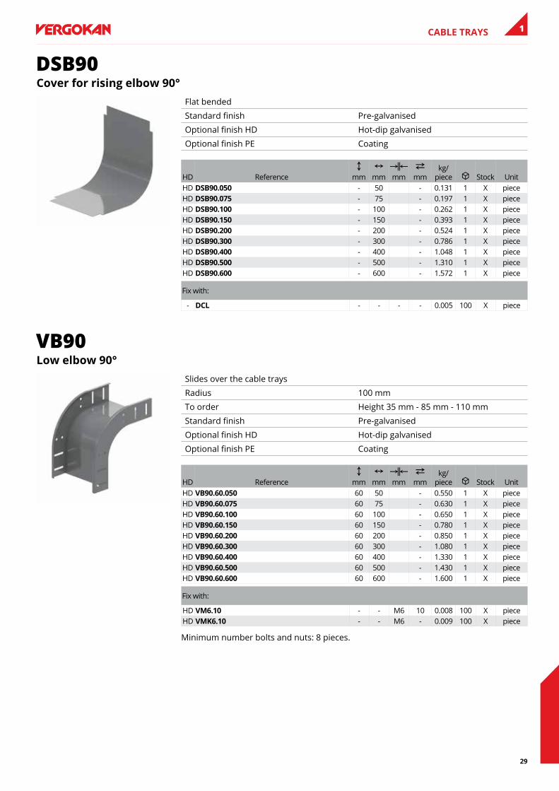
DSB90Cover for rising elbow 90°
Flat bended
Standard finish Pre-galvanised
Optional finish HD Hot-dip galvanised
Optional finish PE Coating
HD ReferenceC
mmN
mmKœL mm
2 mm
kg/piece u Stock Unit
HD Dsb90.050 - 50 - 0.131 1 X pieceHD Dsb90.075 - 75 - 0.197 1 X pieceHD Dsb90.100 - 100 - 0.262 1 X pieceHD Dsb90.150 - 150 - 0.393 1 X pieceHD Dsb90.200 - 200 - 0.524 1 X pieceHD Dsb90.300 - 300 - 0.786 1 X pieceHD Dsb90.400 - 400 - 1.048 1 X pieceHD Dsb90.500 - 500 - 1.310 1 X pieceHD Dsb90.600 - 600 - 1.572 1 X piece
Fix with:
- DCl - - - - 0.005 100 X piece
VB90low elbow 90°
Slides over the cable trays
Radius 100 mm
To order Height 35 mm - 85 mm - 110 mm
Standard finish Pre-galvanised
Optional finish HD Hot-dip galvanised
Optional finish PE Coating
HD ReferenceC
mmN
mmKœL mm
2 mm
kg/piece u Stock Unit
HD Vb90.60.050 60 50 - 0.550 1 X pieceHD Vb90.60.075 60 75 - 0.630 1 X pieceHD Vb90.60.100 60 100 - 0.650 1 X pieceHD Vb90.60.150 60 150 - 0.780 1 X pieceHD Vb90.60.200 60 200 - 0.850 1 X pieceHD Vb90.60.300 60 300 - 1.080 1 X pieceHD Vb90.60.400 60 400 - 1.330 1 X pieceHD Vb90.60.500 60 500 - 1.430 1 X pieceHD Vb90.60.600 60 600 - 1.600 1 X piece
Fix with:
HD VM6.10 - - M6 10 0.008 100 X pieceHD VMK6.10 - - M6 - 0.009 100 X piece
Minimum number bolts and nuts: 8 pieces.
30
CABLE TRAYS1
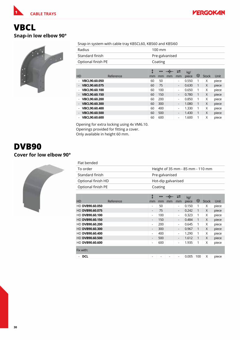
VBCLsnap-in low elbow 90°
Snap-in system with cable tray KBSCL60, KBS60 and KBSI60
Radius 100 mm
Standard finish Pre-galvanised
Optional finish PE Coating
HD ReferenceC
mmN
mmKœL mm
2 mm
kg/piece u Stock Unit
- VbCl90.60.050 60 50 - 0.550 1 X piece- VbCl90.60.075 60 75 - 0.630 1 X piece- VbCl90.60.100 60 100 - 0.650 1 X piece- VbCl90.60.150 60 150 - 0.780 1 X piece- VbCl90.60.200 60 200 - 0.850 1 X piece- VbCl90.60.300 60 300 - 1.080 1 X piece- VbCl90.60.400 60 400 - 1.330 1 X piece- VbCl90.60.500 60 500 - 1.430 1 X piece- VbCl90.60.600 60 600 - 1.600 1 X piece
Opening for extra locking using 4x VM6.10. Openings provided for fitting a cover. Only available in height 60 mm.
DVB90Cover for low elbow 90°
Flat bended
To order Height of 35 mm - 85 mm - 110 mm
Standard finish Pre-galvanised
Optional finish HD Hot-dip galvanised
Optional finish PE Coating
HD ReferenceC
mmN
mmKœL mm
2 mm
kg/piece u Stock Unit
HD DVb90.60.050 - 50 - 0.150 1 X pieceHD DVb90.60.075 - 75 - 0.242 1 X pieceHD DVb90.60.100 - 100 - 0.323 1 X pieceHD DVb90.60.150 - 150 - 0.484 1 X pieceHD DVb90.60.200 - 200 - 0.645 1 X pieceHD DVb90.60.300 - 300 - 0.967 1 X pieceHD DVb90.60.400 - 400 - 1.290 1 X pieceHD DVb90.60.500 - 500 - 1.612 1 X pieceHD DVb90.60.600 - 600 - 1.935 1 X piece
Fix with:
- DCl - - - - 0.005 100 X piece
31
CABLE TRAYS 1
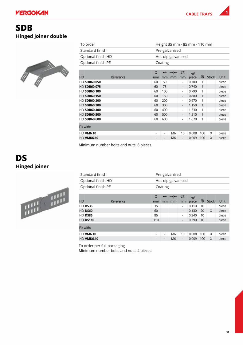
SDBHinged joiner double
To order Height 35 mm - 85 mm - 110 mm
Standard finish Pre-galvanised
Optional finish HD Hot-dip galvanised
Optional finish PE Coating
HD ReferenceC
mmN
mmKœL mm
2 mm
kg/piece u Stock Unit
HD sDb60.050 60 50 - 0.700 1 pieceHD sDb60.075 60 75 - 0.740 1 pieceHD sDb60.100 60 100 - 0.790 1 pieceHD sDb60.150 60 150 - 0.880 1 pieceHD sDb60.200 60 200 - 0.970 1 pieceHD sDb60.300 60 300 - 1.150 1 pieceHD sDb60.400 60 400 - 1.330 1 pieceHD sDb60.500 60 500 - 1.510 1 pieceHD sDb60.600 60 600 - 1.670 1 piece
Fix with:
HD VM6.10 - - M6 10 0.008 100 X pieceHD VMK6.10 - - M6 - 0.009 100 X piece
Minimum number bolts and nuts: 8 pieces.
DSHinged joiner
Standard finish Pre-galvanised
Optional finish HD Hot-dip galvanised
Optional finish PE Coating
HD ReferenceC
mmN
mmKœL mm
2 mm
kg/piece u Stock Unit
HD Ds35 35 - 0.110 10 pieceHD Ds60 60 - 0.130 20 X pieceHD Ds85 85 - 0.340 10 pieceHD Ds110 110 - 0.390 10 piece
Fix with:
HD VM6.10 - - M6 10 0.008 100 X pieceHD VMK6.10 - - M6 - 0.009 100 X piece
To order per full packaging. Minimum number bolts and nuts: 4 pieces.
32
CABLE TRAYS1
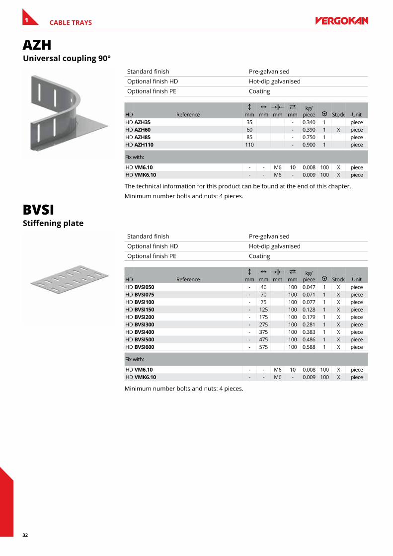
AZHUniversal coupling 90°
Standard finish Pre-galvanised
Optional finish HD Hot-dip galvanised
Optional finish PE Coating
HD ReferenceC
mmN
mmKœL mm
2 mm
kg/piece u Stock Unit
HD aZH35 35 - 0.340 1 pieceHD aZH60 60 - 0.390 1 X pieceHD aZH85 85 - 0.750 1 pieceHD aZH110 110 - 0.900 1 piece
Fix with:
HD VM6.10 - - M6 10 0.008 100 X pieceHD VMK6.10 - - M6 - 0.009 100 X piece
The technical information for this product can be found at the end of this chapter.
Minimum number bolts and nuts: 4 pieces.
BVSIStiffening plate
Standard finish Pre-galvanised
Optional finish HD Hot-dip galvanised
Optional finish PE Coating
HD ReferenceC
mmN
mmKœL mm
2 mm
kg/piece u Stock Unit
HD bVsI050 - 46 100 0.047 1 X pieceHD bVsI075 - 70 100 0.071 1 X pieceHD bVsI100 - 75 100 0.077 1 X pieceHD bVsI150 - 125 100 0.128 1 X pieceHD bVsI200 - 175 100 0.179 1 X pieceHD bVsI300 - 275 100 0.281 1 X pieceHD bVsI400 - 375 100 0.383 1 X pieceHD bVsI500 - 475 100 0.486 1 X pieceHD bVsI600 - 575 100 0.588 1 X piece
Fix with:
HD VM6.10 - - M6 10 0.008 100 X pieceHD VMK6.10 - - M6 - 0.009 100 X piece
Minimum number bolts and nuts: 4 pieces.
33
CABLE TRAYS 1
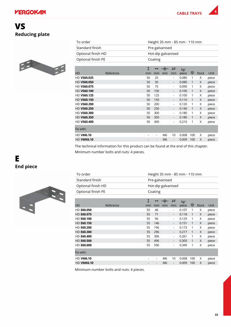
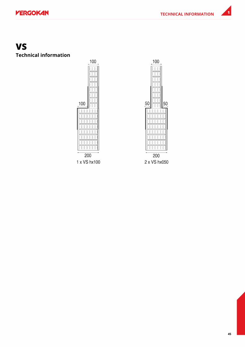
VSReducing plate
To order Height 35 mm - 85 mm - 110 mm
Standard finish Pre-galvanised
Optional finish HD Hot-dip galvanised
Optional finish PE Coating
HD ReferenceC
mmN
mmKœL mm
2 mm
kg/piece u Stock Unit
HD Vs60.025 50 25 - 0.080 1 X pieceHD Vs60.050 50 50 - 0.080 1 X pieceHD Vs60.075 50 75 - 0.090 1 X pieceHD Vs60.100 50 100 - 0.100 1 X pieceHD Vs60.125 50 125 - 0.100 1 X pieceHD Vs60.150 50 150 - 0.110 1 X pieceHD Vs60.200 50 200 - 0.120 1 X pieceHD Vs60.250 50 250 - 0.140 1 X pieceHD Vs60.300 50 300 - 0.180 1 X pieceHD Vs60.350 50 350 - 0.180 1 X pieceHD Vs60.400 50 400 - 0.210 1 X piece
Fix with:
HD VM6.10 - - M6 10 0.008 100 X pieceHD VMK6.10 - - M6 - 0.009 100 X piece
The technical information for this product can be found at the end of this chapter.
Minimum number bolts and nuts: 4 pieces.
Eend piece
To order Height 35 mm - 85 mm - 110 mm
Standard finish Pre-galvanised
Optional finish HD Hot-dip galvanised
Optional finish PE Coating
HD ReferenceC
mmN
mmKœL mm
2 mm
kg/piece u Stock Unit
HD e60.050 55 46 - 0.107 1 X pieceHD e60.075 55 71 - 0.118 1 X pieceHD e60.100 55 96 - 0.129 1 X pieceHD e60.150 55 146 - 0.151 1 X pieceHD e60.200 55 196 - 0.173 1 X pieceHD e60.300 55 296 - 0.217 1 X pieceHD e60.400 55 396 - 0.261 1 X pieceHD e60.500 55 496 - 0.305 1 X pieceHD e60.600 55 596 - 0.349 1 X piece
Fix with:
HD VM6.10 - - M6 10 0.008 100 X pieceHD VMK6.10 - - M6 - 0.009 100 X piece
Minimum number bolts and nuts: 4 pieces.
34
CABLE TRAYS1
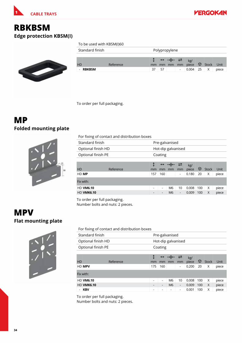
RBKBSMedge protection KbsM(I)
To be used with KBSM(I)60
Standard finish Polypropylene
HD ReferenceC
mmN
mmKœL mm
2 mm
kg/piece u Stock Unit
- RbKbsM 37 57 - 0.004 25 X piece
To order per full packaging.
MPfolded mounting plate
For fixing of contact and distribution boxes
Standard finish Pre-galvanised
Optional finish HD Hot-dip galvanised
Optional finish PE Coating
HD ReferenceC
mmN
mmKœL mm
2 mm
kg/piece u Stock Unit
HD MP 157 160 - 0.180 20 X piece
Fix with:
HD VM6.10 - - M6 10 0.008 100 X pieceHD VMK6.10 - - M6 - 0.009 100 X piece
To order per full packaging. Number bolts and nuts: 2 pieces.
MPVflat mounting plate
For fixing of contact and distribution boxes
Standard finish Pre-galvanised
Optional finish HD Hot-dip galvanised
Optional finish PE Coating
HD ReferenceC
mmN
mmKœL mm
2 mm
kg/piece u Stock Unit
HD MPV 175 160 - 0.200 20 X piece
Fix with:
HD VM6.10 - - M6 10 0.008 100 X pieceHD VMK6.10 - - M6 - 0.009 100 X piece
- KbV - - - - 0.001 100 X piece
To order per full packaging. Number bolts and nuts: 2 pieces.
35
CABLE TRAYS 1
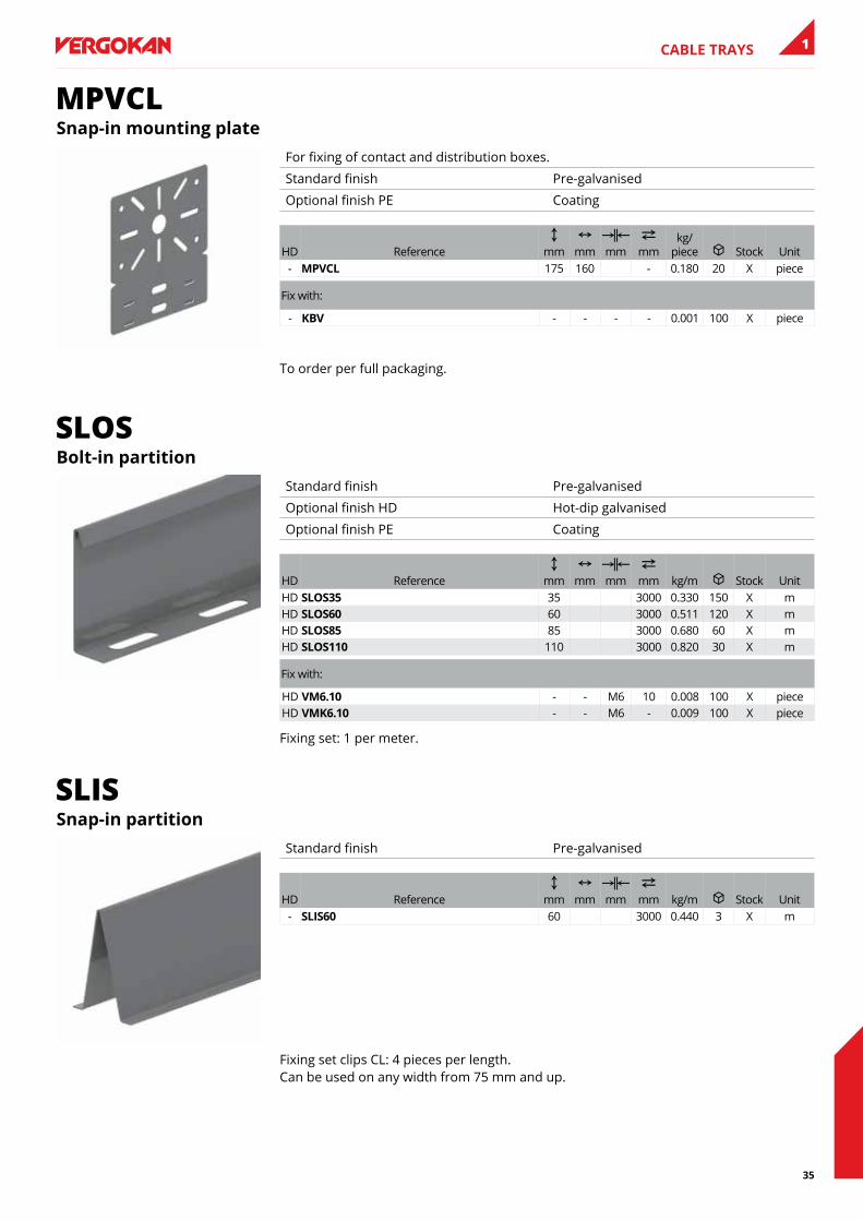
MPVCLsnap-in mounting plate
For fixing of contact and distribution boxes.
Standard finish Pre-galvanised
Optional finish PE Coating
HD ReferenceC
mmN
mmKœL mm
2 mm
kg/piece u Stock Unit
- MPVCl 175 160 - 0.180 20 X piece
Fix with:
- KbV - - - - 0.001 100 X piece
To order per full packaging.
SLOSbolt-in partition
Standard finish Pre-galvanised
Optional finish HD Hot-dip galvanised
Optional finish PE Coating
HD ReferenceC
mmN
mmKœL mm
2 mm kg/m u Stock Unit
HD slOs35 35 3000 0.330 150 X mHD slOs60 60 3000 0.511 120 X mHD slOs85 85 3000 0.680 60 X mHD slOs110 110 3000 0.820 30 X m
Fix with:
HD VM6.10 - - M6 10 0.008 100 X pieceHD VMK6.10 - - M6 - 0.009 100 X piece
Fixing set: 1 per meter.
SLISsnap-in partition
Standard finish Pre-galvanised
HD ReferenceC
mmN
mmKœL mm
2 mm kg/m u Stock Unit
- slIs60 60 3000 0.440 3 X m
Fixing set clips CL: 4 pieces per length. Can be used on any width from 75 mm and up.
36
CABLE TRAYS1
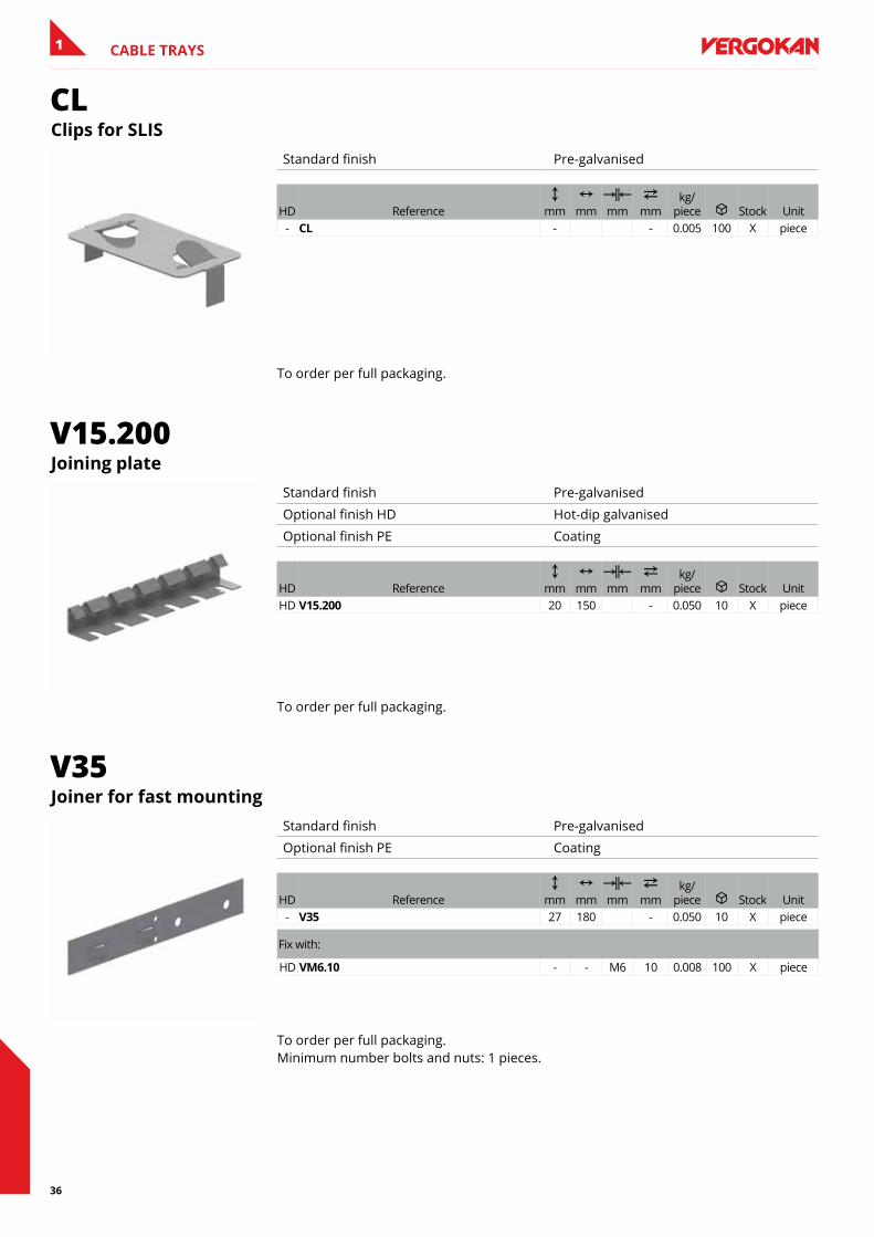
CLClips for slIs
Standard finish Pre-galvanised
HD ReferenceC
mmN
mmKœL mm
2 mm
kg/piece u Stock Unit
- Cl - - 0.005 100 X piece
To order per full packaging.
V15.200Joining plate
Standard finish Pre-galvanised
Optional finish HD Hot-dip galvanised
Optional finish PE Coating
HD ReferenceC
mmN
mmKœL mm
2 mm
kg/piece u Stock Unit
HD V15.200 20 150 - 0.050 10 X piece
To order per full packaging.
V35Joiner for fast mounting
Standard finish Pre-galvanised
Optional finish PE Coating
HD ReferenceC
mmN
mmKœL mm
2 mm
kg/piece u Stock Unit
- V35 27 180 - 0.050 10 X piece
Fix with:
HD VM6.10 - - M6 10 0.008 100 X piece
To order per full packaging. Minimum number bolts and nuts: 1 pieces.
37
CABLE TRAYS 1
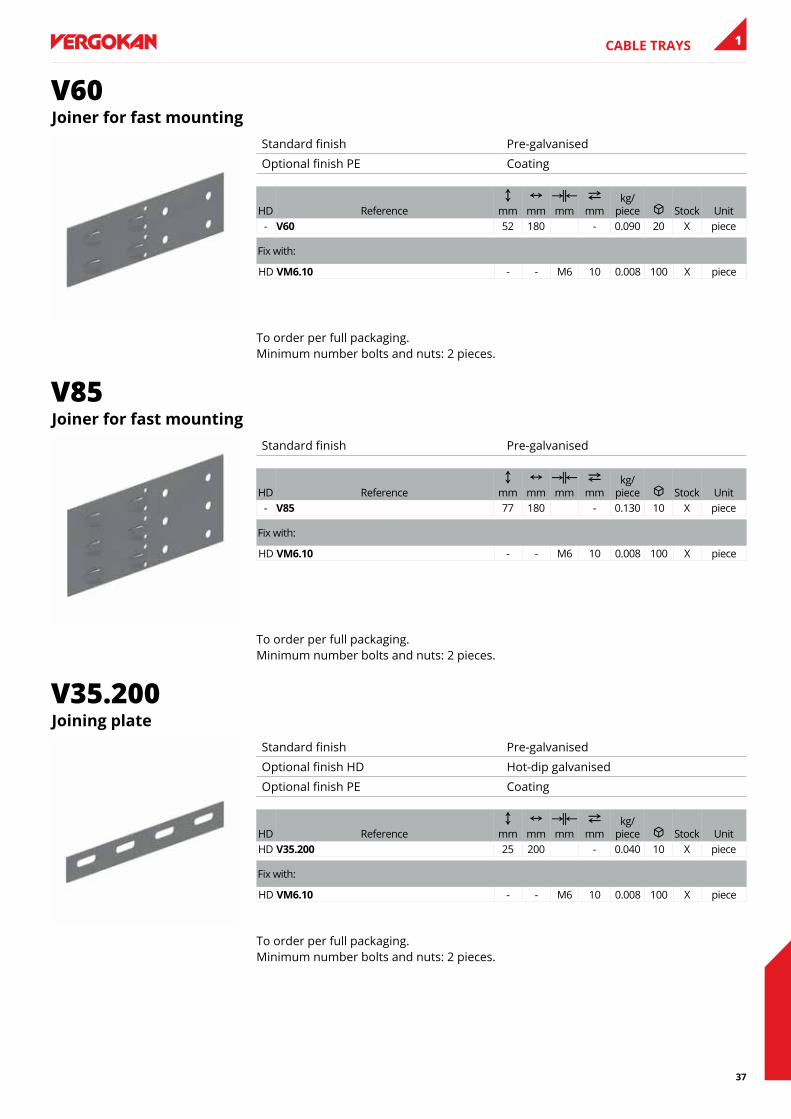
V60Joiner for fast mounting
Standard finish Pre-galvanised
Optional finish PE Coating
HD ReferenceC
mmN
mmKœL mm
2 mm
kg/piece u Stock Unit
- V60 52 180 - 0.090 20 X piece
Fix with:
HD VM6.10 - - M6 10 0.008 100 X piece
To order per full packaging. Minimum number bolts and nuts: 2 pieces.
V85Joiner for fast mounting
Standard finish Pre-galvanised
HD ReferenceC
mmN
mmKœL mm
2 mm
kg/piece u Stock Unit
- V85 77 180 - 0.130 10 X piece
Fix with:
HD VM6.10 - - M6 10 0.008 100 X piece
To order per full packaging. Minimum number bolts and nuts: 2 pieces.
V35.200Joining plate
Standard finish Pre-galvanised
Optional finish HD Hot-dip galvanised
Optional finish PE Coating
HD ReferenceC
mmN
mmKœL mm
2 mm
kg/piece u Stock Unit
HD V35.200 25 200 - 0.040 10 X piece
Fix with:
HD VM6.10 - - M6 10 0.008 100 X piece
To order per full packaging. Minimum number bolts and nuts: 2 pieces.
38
CABLE TRAYS1
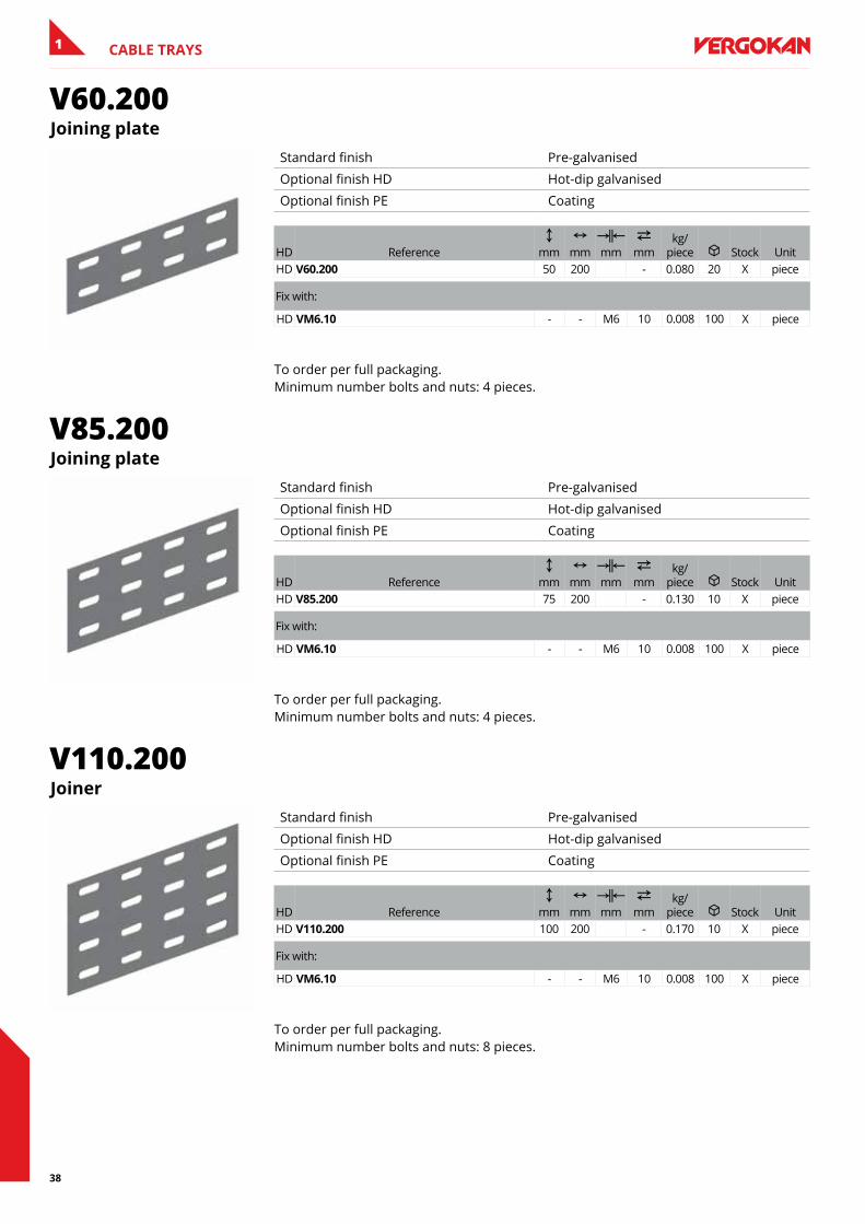
V60.200Joining plate
Standard finish Pre-galvanised
Optional finish HD Hot-dip galvanised
Optional finish PE Coating
HD ReferenceC
mmN
mmKœL mm
2 mm
kg/piece u Stock Unit
HD V60.200 50 200 - 0.080 20 X piece
Fix with:
HD VM6.10 - - M6 10 0.008 100 X piece
To order per full packaging. Minimum number bolts and nuts: 4 pieces.
V85.200Joining plate
Standard finish Pre-galvanised
Optional finish HD Hot-dip galvanised
Optional finish PE Coating
HD ReferenceC
mmN
mmKœL mm
2 mm
kg/piece u Stock Unit
HD V85.200 75 200 - 0.130 10 X piece
Fix with:
HD VM6.10 - - M6 10 0.008 100 X piece
To order per full packaging. Minimum number bolts and nuts: 4 pieces.
V110.200Joiner
Standard finish Pre-galvanised
Optional finish HD Hot-dip galvanised
Optional finish PE Coating
HD ReferenceC
mmN
mmKœL mm
2 mm
kg/piece u Stock Unit
HD V110.200 100 200 - 0.170 10 X piece
Fix with:
HD VM6.10 - - M6 10 0.008 100 X piece
To order per full packaging. Minimum number bolts and nuts: 8 pieces.
39
CABLE TRAYS 1
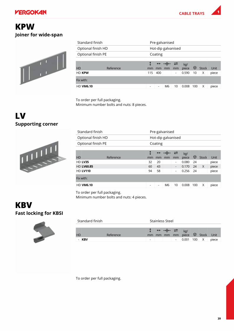
KPWJoiner for wide-span
Standard finish Pre-galvanised
Optional finish HD Hot-dip galvanised
Optional finish PE Coating
HD ReferenceC
mmN
mmKœL mm
2 mm
kg/piece u Stock Unit
HD KPW 115 400 - 0.590 10 X piece
Fix with:
HD VM6.10 - - M6 10 0.008 100 X piece
To order per full packaging. Minimum number bolts and nuts: 8 pieces.
LVsupporting corner
Standard finish Pre-galvanised
Optional finish HD Hot-dip galvanised
Optional finish PE Coating
HD ReferenceC
mmN
mmKœL mm
2 mm
kg/piece u Stock Unit
HD lV35 32 20 - 0.080 24 pieceHD lV60.85 60 43 - 0.170 24 X pieceHD lV110 94 58 - 0.256 24 piece
Fix with:
HD VM6.10 - - M6 10 0.008 100 X piece
To order per full packaging. Minimum number bolts and nuts: 4 pieces.
KBVfast locking for KbsI
Standard finish Stainless Steel
HD ReferenceC
mmN
mmKœL mm
2 mm
kg/piece u Stock Unit
- KbV - - 0.001 100 X piece
To order per full packaging.
40
CABLE TRAYS1
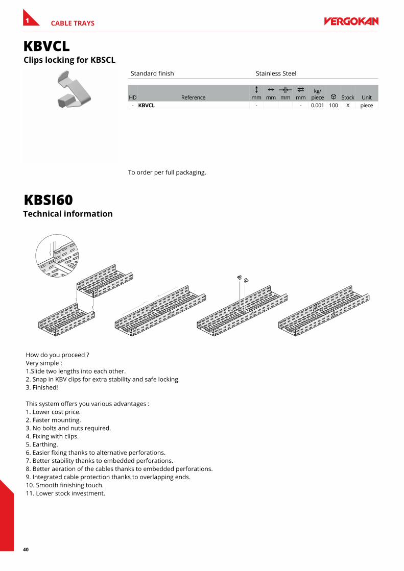
KBVCLClips locking for KbsCl
Standard finish Stainless Steel
HD ReferenceC
mmN
mmKœL mm
2 mm
kg/piece u Stock Unit
- KbVCl - - 0.001 100 X piece
To order per full packaging.
KBSI60Technical information
How do you proceed ? Very simple : 1.Slide two lengths into each other. 2. Snap in KBV clips for extra stability and safe locking. 3. Finished! This system offers you various advantages : 1. Lower cost price. 2. Faster mounting. 3. No bolts and nuts required. 4. Fixing with clips. 5. Earthing. 6. Easier fixing thanks to alternative perforations. 7. Better stability thanks to embedded perforations. 8. Better aeration of the cables thanks to embedded perforations. 9. Integrated cable protection thanks to overlapping ends. 10. Smooth finishing touch. 11. Lower stock investment.
41
1TECHNICAL INFORMATION
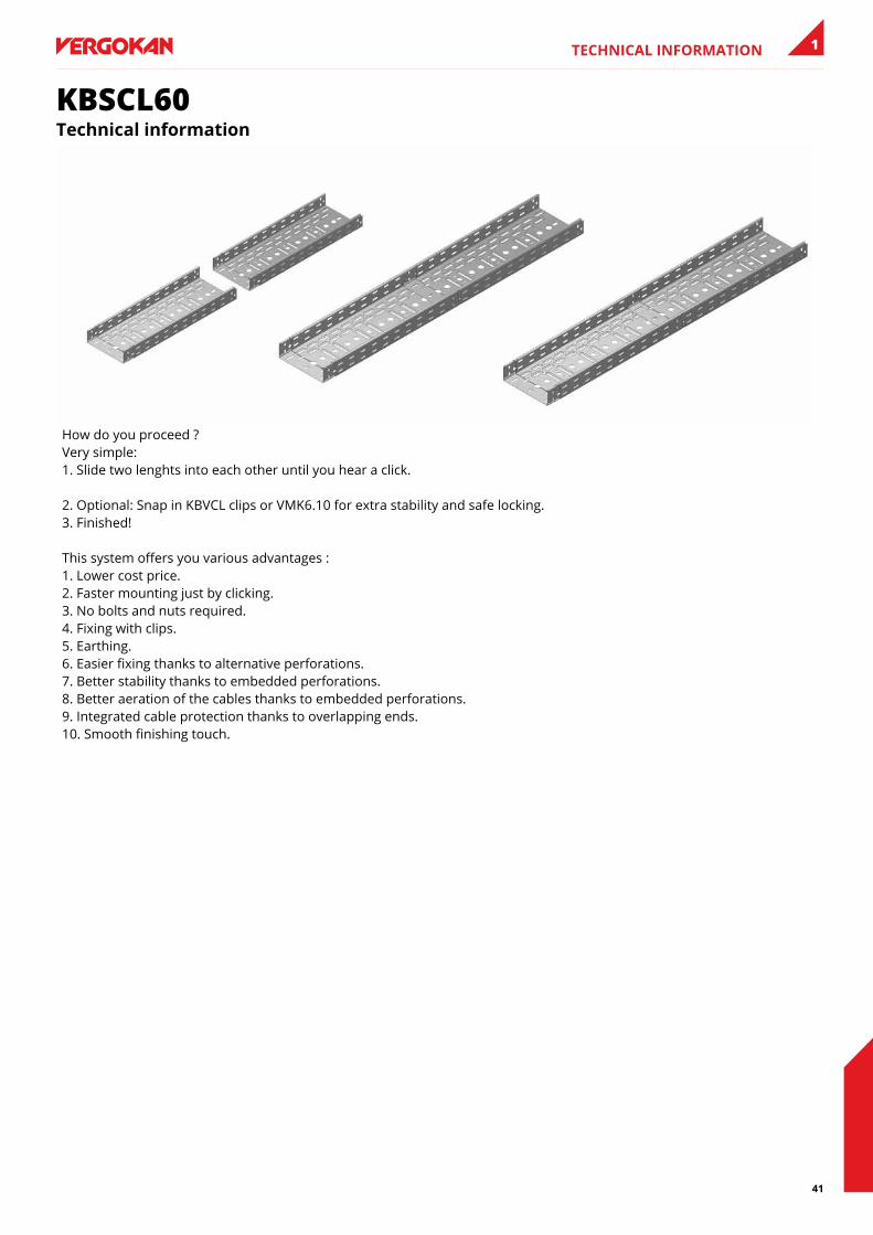
KBSCL60Technical information
How do you proceed ? Very simple: 1. Slide two lenghts into each other until you hear a click. 2. Optional: Snap in KBVCL clips or VMK6.10 for extra stability and safe locking. 3. Finished! This system offers you various advantages : 1. Lower cost price. 2. Faster mounting just by clicking. 3. No bolts and nuts required. 4. Fixing with clips. 5. Earthing. 6. Easier fixing thanks to alternative perforations. 7. Better stability thanks to embedded perforations. 8. Better aeration of the cables thanks to embedded perforations. 9. Integrated cable protection thanks to overlapping ends. 10. Smooth finishing touch.
42
1 TECHNICAL INFORMATION TeCHnICal InfORMaTIOn
KBSM(I)60Technical information
43
1TECHNICAL INFORMATION
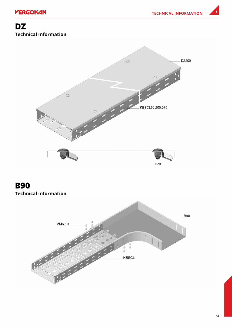
DZTechnical information
B90Technical information
44
1 TECHNICAL INFORMATION
ASTechnical information
AZHTechnical information
45
1TECHNICAL INFORMATION
VSTechnical information