04059-nor 2700a manual - norrisealwellmark.com · c.s.nace/316/316 n 316/316/316 s ... 150 285 02...
TRANSCRIPT
P.O. Box 40525 · Houston, Texas USA 77240-0525Tel: 713·466·3552 · Fax: 713·896·7386 www.norriseal.com1001-0113O — ©2013, January 2013
INTRODUCTION
C A U T I O N !
The instructions provided herein shouldbe completely reviewed and understoodprior to installing, operating or repairingthis equipment. All ATTENTION, CAU-TION, DANGER and WARNING notesmust be strictly observed to prevent seri-ous injury or equipment malfunction.
ScopeThis manual includes installation,operation and maintenance infor-mation for 1.5 through 6.0-in.Norriseal Series 1001, 1001A, and1001XL Level Controllers.
DescriptionThe Series 1001, 1001A, and 1001XLLevel Controllers are designed forgeneral purpose use in liquid leveland interface control applicationscalling for either modulating(Throttle) or on/off (Snap) pneumaticservice and can be direct or reverseacting. Electric switch models arealso available.
Norriseal level controllers areequipped standard with horizontalor vertical PVC 1.88 x 12-in. displac-ers. Displacer options include Acrylicand 316L S.S. materials in variouslengths and diameters, includinghinged models, to accommodate awide range of control applications.
The 1001 has a smaller case than the1001A or 1001XL and has a knurledknob screw type closure. The 1001A
and 1001XL have lever latch doorclosing mechanisms and have asealed door. The 1001 and 1001Ahave the case mounted left or rightof the body, while the 1001XL is cen-ter-back mounted.
C A U T I O N !
Before disassembly or maintenance, allpressures in this device must be relieved.Failure to relieve pressures may result inpersonal injury or device damage. Theresulting uncontrolled venting or spillingof process fluids may cause personalinjury, loss of process control or environ-mental contamination.
Controller IdentificationController model numbers are typi-cally 13 positions long (example:2SM60-SRDA-BG). Refer to Table 1— Model Designation on page 2 forspecific information on the controllernomenclature.
A nameplate attached to the inside ofthe case by the lower door hingeincludes the controller model andserial numbers as well as other infor-mation pertinent to the controllerassembly, such as supply and out-put pressures, displacer material andrating, body size and material, ANSIclass, and pressure and temperaturelimits.
Always use only Norriseal replace-ment parts when servicing level con-trollers. Please refer to the serial andmodel numbers when orderingreplacement parts.
Page 1 of 12
OPERATING AND MAINTENANCE MANUALSeries 1001, 1001A, 1001XL Level Control
CONTENTSPAGE
INTRODUCTION 1Scope 1Description 1Controller Identification 1PRINCIPLE OF OPERATION 3PILOT OPERATION 41.0 LEVEL CONTROLLER
INSTALLATION ANDSTART-UP 5
1.0 LEVEL ADJUSTMENT 61.2 LIQUID LEVEL INTERFACE 62.0 LEVEL CONTROLLER
MAINTENANCE 72.1 LEVEL CONTROLLER
PREVENTIVE MAINTENANCE 72.2 LEVEL CONTROLLER DISASSEMBLY 72.3 LEVEL CONTROLLER REASSEMBLY 72.4 PILOT REMOVAL/REPLACEMENT 82.5 LEVEL CONTROLLER DISASSEMBLY
CASE MOUNTING CONVERSION 92.6 LEVEL CONTROLLER DISASSEMBLY
PILOT ACTION CONVERSION 92.7 LEVEL CONTROLLER
BODY DISASSEMBLY 92.8 LEVEL CONTROLLER
BODY REASSEMBLY 93.0 REPAIR KITS 10
TABLESTable 1 — Model Designation 2Table 2 — Wiring Diagrams 10Tabla 3 — Trouble Diagnosis 11
ABS
Quality
Evaluations, Inc.
Managem
ent System Certi
fication

P.O. Box 40525 · Houston, Texas USA 77240-0525Tel: 713·466·3552 · Fax: 713·896·7386 www.norriseal.com 1001-0113O — ©2013, January 2013
OPERATING AND MAINTENANCE MANUAL
Series 1001, 1001A, 1001XL Level Control
Page 2 of 12
End Connection Size 1.5 in. 152 in. 23 in. 34 in. 46 in. 6
Material – Body/Shaft/BlockC.S./303/303 –C.S.NACE/316/316 N316/316/316 S316NACE/316/316 R
Case MountingLeft Hand LRight Hand R
AcciPilot ActionDirect Acting DReverse Acting R
Service ConditionStandard (1001 Only) AVibration (StandardOn 1001A/1001XL) B
Pressure GaugesBronze 0–30 psi –Bronze 0–60 H316 SS 0–30 J316 SS 0–60 KLiquid Filled 0–30 Brz (1001A/XL) LLiquid Filled 0–60 Brz (1001A/XL) M
Seal/Bearing Material/Temp Buna/303/180°F AViton/303/400°F FEPR/303/275°F EAflas/316/400°F S
EnclosureStandard Case (1001 Only) ASealed Case/Cover GSealed Case/CoverPiped Exhaust HSealed Case/CoverMarine Internals KSealed Case/CoverPiped Exhaust andMarine Internals J
DisplacersPVC (Standard): –20 to 140°F(6170 psi)(6170 psi)Acrylic: –20 to 200°FAluminum: –70 to 400°F(6170 psi)316L SS: –70 to 400°(2000 psi)
PilotPneumatic Snap (On/Off) SPneumatic Throttle (Modulating) TEnviroSave (Snap) BEnviroSave – Vibration CElectric DPDT – Ex-Proof DElectric SPDT – Ex-Proof EElectric DPDT – Splash-Proof FElectric SPDT – Splash-Proof OElectric DPDT – Hermetic Seal LElectric SPDT – Hermetic Seal K
End Connection StyleScrewed MNPT SMFlanged – Raised Face RFFlanged – Ring Type Joint RJFlanged – Special 4 Bolt SFBeveled – Slip On BSBeveled – Butt Weld Sch 40 B4Beveled – Butt Weld Sch 80 B8Beveled – Butt Weld Sch 160 B1Beveled – Butt Weld SCH XXH BXGrooved GVSocket Weld SWUnion – Dover DUUnion – Yale YUUnion – Acme AU
Pressure RatingANSI RatingANSI 150 285 02300 740 07400 960 09
1000 10600 1480 14
1500 152000 20
900 2220 212500 253000 30
1500 3750 364000 405000 506000 60
2500 6170 60
Series10011001A1001XL
TA B L A 1 . D E T E R M I N A C I Ó N D E L M O D E L O
1001A 2 SM 60 - S R D A - B G
P.O. Box 40525 · Houston, Texas USA 77240-0525Tel: 713·466·3552 · Fax: 713·896·7386 www.norriseal.com1001-0113O — ©2013, January 2013
WA R N I N G !
Maximum allowable pressures for thelevel controller body and the maximumallowable pressure at the maximum tem-perature for the level controller are shownon the nameplate mounted in the case. Ifpressure to the level controller is capa-ble of exceeding these limits, install reliefvalves or other over-pressure protectiondevices in the pressure lines.
C A U T I O N !
When ordered, the controller body, dis-placer material, and configuration wereselected to meet particular pressure, tem-perature, and fluid conditions. Bodies anddisplacers are limited in their operatingpressure and temperature ranges as wellas their ability to resist corrosion. Do notapply any other conditions to the controller without first contacting yourNorriseal sales office or your sales representative.
PRINCIPLE OF OPERATION
Force Balance PrincipleThe operation of the Series 1001,1001A, and the 1001XL LevelControllers is based on the ForceBalance Principle. A spring balancesthe weight of a displacement typesensing element. As liquid risesaround the displacer, the amount offorce available to the pilot is pro-portional to the weight of the liquiddisplaced. The force available istransmitted to the pilot thrust pinthrough a lever and fulcrum. Thehigher the level, the greater the forceavailable to the pilot thrust pin.
The control is direct acting (risinglevel increases pilot output) whenthe pivot point of the lever is on thespring side of the control case. Thecontrol is reverse acting (rising level
decreases pilot output) when thepivot point of the lever is on theopposite side of the control casefrom the spring.
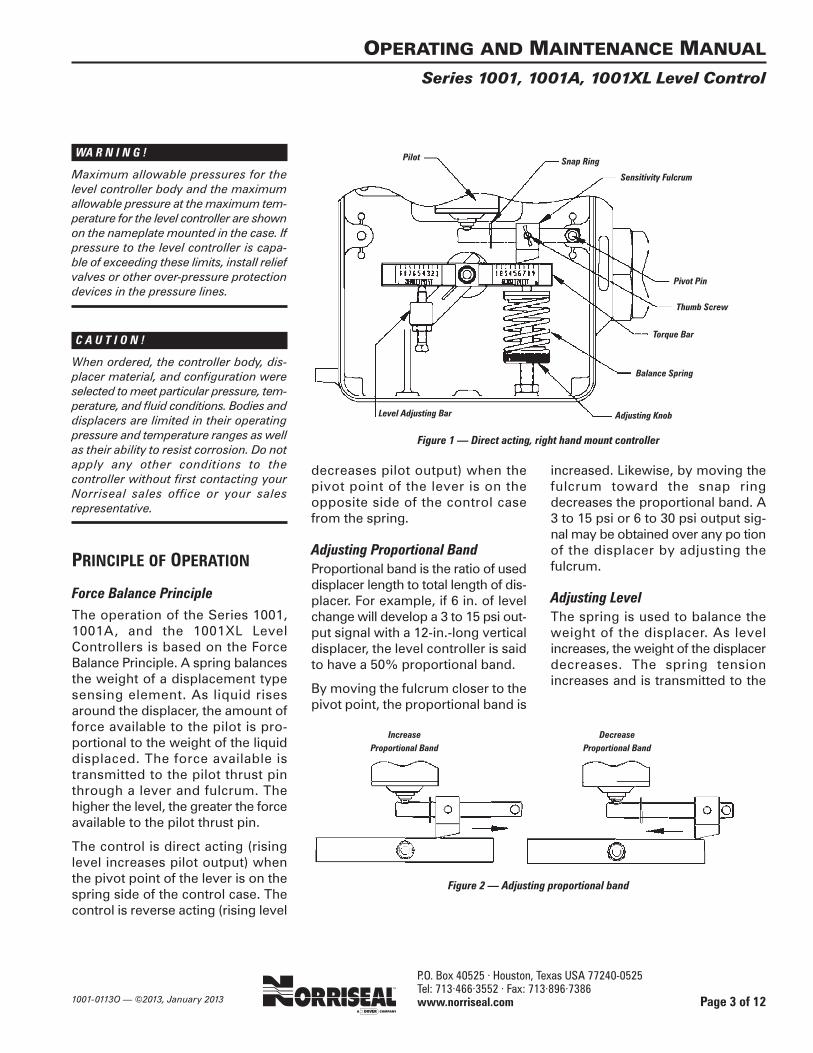
Adjusting Proportional BandProportional band is the ratio of useddisplacer length to total length of dis-placer. For example, if 6 in. of levelchange will develop a 3 to 15 psi out-put signal with a 12-in.-long verticaldisplacer, the level controller is saidto have a 50% proportional band.
By moving the fulcrum closer to thepivot point, the proportional band is
increased. Likewise, by moving thefulcrum toward the snap ringdecreases the proportional band. A3 to 15 psi or 6 to 30 psi output sig-nal may be obtained over any po tion of the displacer by adjusting the fulcrum.
Adjusting LevelThe spring is used to balance theweight of the displacer. As levelincreases, the weight of the displacerdecreases. The spring tensionincreases and is transmitted to the
OPERATING AND MAINTENANCE MANUAL
Series 1001, 1001A, 1001XL Level Control
Page 3 of 12
Figure 1 — Direct acting, right hand mount controller
Figure 2 — Adjusting proportional band
Pilot Snap Ring
Sensitivity Fulcrum
Pivot Pin
Thumb Screw
Torque Bar
Balance Spring
Adjusting KnobLevel Adjusting Bar
DecreaseProportional Band
IncreaseProportional Band
P.O. Box 40525 · Houston, Texas USA 77240-0525Tel: 713·466·3552 · Fax: 713·896·7386 www.norriseal.com 1001-0113O — ©2013, January 2013
pilot thrust pin through the lever andfulcrum.
By increasing tension on the spring,a lower level is sensed. By decreas-ing tension on the spring, a higherlevel is required to produce the sameforce as before.
Spring compression can be reducedto a point where a hydrocarbon liq-uid level will rise above the displacerwithout transmitting enough forceto the pilot to produce an output. Ifproperly adjusted, water, with ahigher specific gravity, will rise to thedisplacer resulting in a change inweight of the displacer. This will produce an output, thus sensing theinterface level of water and hydro-carbon. This wide range of controlmakes liquid interface sensing possible.
PILOT OPERATIONAs described in Principle ofOperation, force from the balancespring is transmitted via the leverand fulcrum to the thrust pin of thepilot.
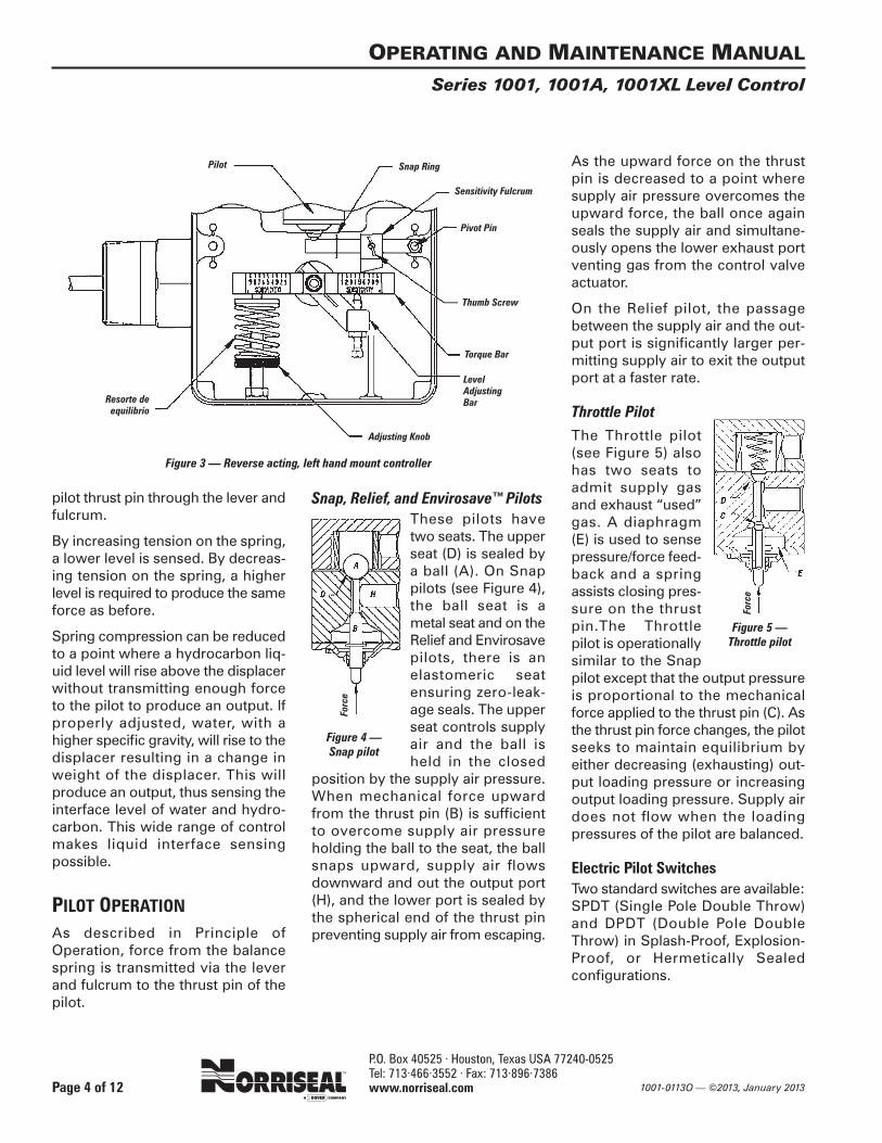
Snap, Relief, and Envirosave™PilotsThese pilots havetwo seats. The upperseat (D) is sealed bya ball (A). On Snappilots (see Figure 4),the ball seat is ametal seat and on theRelief and Envirosavepilots, there is anelastomeric seatensuring zero-leak-age seals. The upperseat controls supplyair and the ball isheld in the closed
position by the supply air pressure.When mechanical force upwardfrom the thrust pin (B) is sufficientto overcome supply air pressureholding the ball to the seat, the ballsnaps upward, supply air flowsdownward and out the output port(H), and the lower port is sealed bythe spherical end of the thrust pinpreventing supply air from escaping.
As the upward force on the thrustpin is decreased to a point wheresupply air pressure overcomes theupward force, the ball once againseals the supply air and simultane-ously opens the lower exhaust portventing gas from the control valveactuator.
On the Relief pilot, the passagebetween the supply air and the out-put port is significantly larger per-mitting supply air to exit the outputport at a faster rate.
Throttle PilotThe Throttle pilot(see Figure 5) alsohas two seats toadmit supply gasand exhaust “used”gas. A diaphragm(E) is used to sensepressure/force feed-back and a springassists closing pres-sure on the thrustpin.The Throttlepilot is operationallysimilar to the Snappilot except that the output pressureis proportional to the mechanicalforce applied to the thrust pin (C). Asthe thrust pin force changes, the pilotseeks to maintain equilibrium byeither decreasing (exhausting) out-put loading pressure or increasingoutput loading pressure. Supply airdoes not flow when the loadingpressures of the pilot are balanced.
Electric Pilot SwitchesTwo standard switches are available:SPDT (Single Pole Double Throw)and DPDT (Double Pole DoubleThrow) in Splash-Proof, Explosion-Proof, or Hermetically Sealed configurations.
OPERATING AND MAINTENANCE MANUAL
Series 1001, 1001A, 1001XL Level Control
Page 4 of 12
Pilot
Sensitivity Fulcrum
Pivot Pin
Thumb Screw
Torque Bar
Level AdjustingBar
Adjusting Knob
Snap Ring
Figure 3 — Reverse acting, left hand mount controller
Resorte de equilibrio
Figure 4 —Snap pilot
Forc
e
Figure 5 — Throttle pilot
Forc
e
P.O. Box 40525 · Houston, Texas USA 77240-0525Tel: 713·466·3552 · Fax: 713·896·7386 www.norriseal.com1001-0113O — ©2013, January 2013
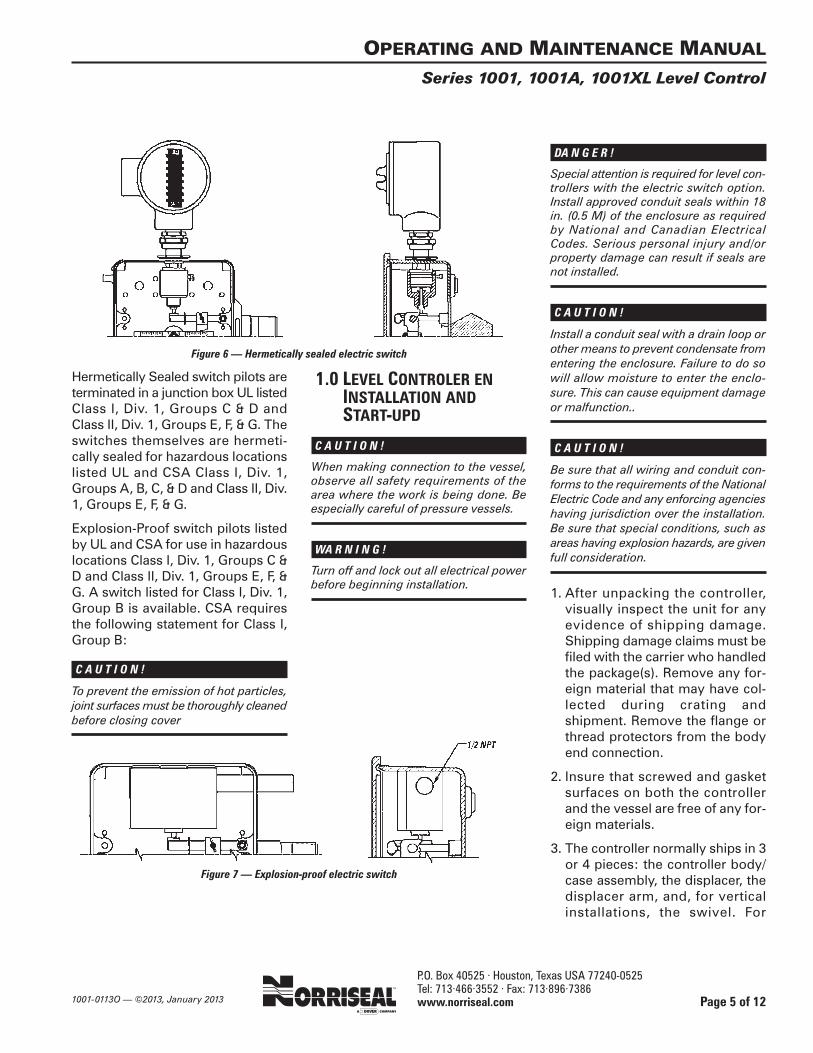
Hermetically Sealed switch pilots areterminated in a junction box UL listedClass I, Div. 1, Groups C & D andClass II, Div. 1, Groups E, F, & G. Theswitches themselves are hermeti-cally sealed for hazardous locationslisted UL and CSA Class I, Div. 1,Groups A, B, C, & D and Class II, Div.1, Groups E, F, & G.
Explosion-Proof switch pilots listedby UL and CSA for use in hazardouslocations Class I, Div. 1, Groups C &D and Class II, Div. 1, Groups E, F, &G. A switch listed for Class I, Div. 1,Group B is available. CSA requiresthe following statement for Class I,Group B:
C A U T I O N !
To prevent the emission of hot particles,joint surfaces must be thoroughly cleanedbefore closing cover
1.0 LEVEL CONTROLER ENINSTALLATION ANDSTART-UPD
C A U T I O N !
When making connection to the vessel,observe all safety requirements of thearea where the work is being done. Beespecially careful of pressure vessels.
WA R N I N G !
Turn off and lock out all electrical powerbefore beginning installation.
DA N G E R !
Special attention is required for level con-trollers with the electric switch option.Install approved conduit seals within 18in. (0.5 M) of the enclosure as requiredby National and Canadian ElectricalCodes. Serious personal injury and/orproperty damage can result if seals arenot installed.
C A U T I O N !
Install a conduit seal with a drain loop orother means to prevent condensate fromentering the enclosure. Failure to do sowill allow moisture to enter the enclo-sure. This can cause equipment damageor malfunction..
C A U T I O N !
Be sure that all wiring and conduit con-forms to the requirements of the NationalElectric Code and any enforcing agencieshaving jurisdiction over the installation.Be sure that special conditions, such asareas having explosion hazards, are givenfull consideration.
1. After unpacking the controller,visually inspect the unit for anyevidence of shipping damage.Shipping damage claims must befiled with the carrier who handledthe package(s). Remove any for-eign material that may have col-lected during crating andshipment. Remove the flange orthread protectors from the bodyend connection.
2. Insure that screwed and gasketsurfaces on both the controllerand the vessel are free of any for-eign materials.
3. The controller normally ships in 3or 4 pieces: the controller body/case assembly, the displacer, thedisplacer arm, and, for verticalinstallations, the swivel. For
OPERATING AND MAINTENANCE MANUAL
Series 1001, 1001A, 1001XL Level Control
Page 5 of 12
Figure 6 — Hermetically sealed electric switch
Figure 7 — Explosion-proof electric switch
P.O. Box 40525 · Houston, Texas USA 77240-0525Tel: 713·466·3552 · Fax: 713·896·7386 www.norriseal.com 1001-0113O — ©2013, January 2013
this(reason some field assemblyis required. Insert the displacerarm in the opening in the con-troller body. Carefully align the dis-placer arm in the body shaft andscrew the arm into the shaft. If thisis a vertical installation, screw theswivel onto the free end of the dis-placer arm. Screw the displacereither into the free end of the dis-placer arm (horizontal application)or the free end of the swivel (ver-tical application).
4. Install the controller using goodpiping practice. For flanged bod-ies, use a suitable gasket betweenthe body and vessel flanges. Forthreaded (NPT) bodies, use TFEtape or pipe thread sealant onexternal pipe threads.
C A U T I O N !
The Bodies are rated ANSI 150, 300, 600,900, 1500 or 2500 class. Do not install thelevel controller in a system where theworking pressures can exceed thosemarked on the nameplate.
5. Connect instrument air to the controller supply connection onthe back of the controller. The supply and output connections areclearly marked. On the 1001 con-troller, it is the upper connection.On the 1001A and 1001XL con-trollers, it is the connection on theright when looking at the rear ofthe controller case. Connect thecontrol valve signal line to the out-put connection.
6. Open the case and rock the torquebar by hand to verify the displacerarm moves freely and is NOT rest-ing against the vessel nozzle orother obstruction. The arm mustbe reasonably centered in the con-nection opening, parallel to the
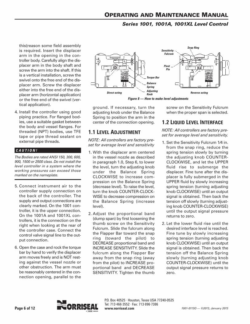
ground. If necessary, turn theadjusting knob under the BalanceSpring to position the arm in thecenter of the connection opening.
1.1 LEVEL ADJUSTMENT
NOTE: All controllers are factory pre-set for average level and sensitivity
1. With the displacer arm centeredin the vessel nozzle as describedin paragraph 1.0, Step 6, to lowerthe level, turn the adjusting knobunder the Balance Spring CLOCKWISE to increase com-pression on the Balance Spring(decrease level). To raise the level,turn the knob COUNTER-CLOCK-WISE to decrease compression onthe Balance Spring (increaselevel).
2. Adjust the proportional band(dump span) by first loosening thethumb screw on the SensitivityFulcrum. Slide the fulcrum alongthe Flapper Bar toward the snapring (toward the pilot) toDECREASE proportional band andINCREASE SENSITIVITY. Slide thefulcrum along the Flapper Baraway from the snap ring (awayfrom the pilot) to INCREASE pro-portional band and DECREASESENSITIVITY. Tighten the thumb
screw on the Sensitivity Fulcrumwhen the proper span is selected.
1.2 LIQUID LEVEL INTERFACENOTE: All controllers are factory pre-set for average level and sensitivity.
1. Set the Sensitivity Fulcrum 1⁄4 in.from the snap ring, reduce thespring tension slowly by turningthe adjusting knob COUNTER-CLOCKWISE, and let the UPPERfluid rise to submerge the displacer. Fine tune after the dis-placer is fully submerged in theUPPER fluid by slowly increasingspring tension (turning adjustingknob CLOCKWISE) until an outputsignal is obtained. Then back thetension off slowly (turning adjust-ing knob COUNTER-CLOCKWISE)until the output signal pressurereturns to zero.
2. Let the lower fluid rise until thedesired interface level is reached.Fine tune by slowly increasingspring tension (turning adjustingknob CLOCKWISE) until an outputsignal is obtained. Then back thetension off the Balance Springslowly (turning adjusting knobCOUNTER-CLOCKWISE) until theoutput signal pressure returns tozero.
OPERATING AND MAINTENANCE MANUAL
Series 1001, 1001A, 1001XL Level Control
Page 6 of 12
Pivot Pin
Torque Bar
BalanceSpringAdjustingKnob
SensitivityFulcrum
Snap Ring
Direct acting Reverse acting
Figure 8 — How to make level adjustments
P.O. Box 40525 · Houston, Texas USA 77240-0525Tel: 713·466·3552 · Fax: 713·896·7386 www.norriseal.com1001-0113O — ©2013, January 2013
3. If a longer dump span is desired,move the fulcrum farther awayfrom the snap ring and repeat theabove procedure.
2.0 LEVEL CONTROLLERMAINTENANCE
WA R N I N G !
Before attempting any repairs, isolate thecontroller from the system and make surethat all pressure is released from the controller body. Shut off and vent supplyand output (signal air) lines to the controller. On electric pilots, disconnect allpower to the controller.
1. Isolate the controller from theprocess.
2. Shut off the output and supplylines to the controller. If the pilot iselectric, turn off and lock out allelectrical power to the controller.
3. Release the process pressure.
Controller parts are built to withstanda great deal of wear under normaloperating conditions and will rarelyneed to be repaired. Should repairbe necessary, the following sectionsdescribe the procedures for disas-sembling and re-assembling the
controller for normal maintenanceand troubleshooting.
2.1 LEVEL CONTROLLERPREVENTUIVE MAINTENANCE
1. In normal service, O-Rings and the bearings on the main shaftshould last for many years. If aleak occurs, replace the O-Rings.Order a Level Seal Kit (LSK) from Norriseal.
2. If the controller is used in high-paraffin service or interface con-trol with a horizontal displacer,remove and inspect the body ofthe controller after three (3)months of service and check fordebris buildup. Future inspectiontimes after initial inspection canbe gauged by how much buildupof debris occurred in the initialthree (3) months of service.
2.2 LEVEL CONTROLLERDISASSEMBLY
NOTE: These instructions do notapply to the pilot. See Paragraph 2.4for instructions for removing and/orreplacing the pilot.
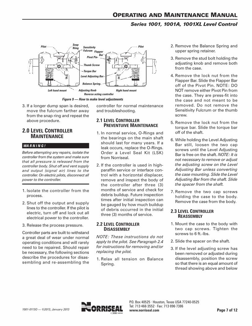
1. Relax all tension on BalanceSpring.
2. Remove the Balance Spring andupper spring retainer.
3. Remove the stud bolt holding theadjusting knob and remove bothfrom the case.
4. Remove the lock nut from theFlapper Bar. Slide the Flapper Baroff of the Pivot Pin. NOTE: DONOT remove either Pivot Pin fromthe case. They are press-fit intothe case and not meant to beremoved. Do not remove theSensitivity Fulcrum or the thumbscrew.
5. Remove the lock nut from thetorque bar. Slide the torque baroff of the shaft.
6. While holding the Level AdjustingBar still, loosen the two capscrews until the Level AdjustingBar is free on the shaft. NOTE: It isnot necessary to remove or adjustthe adjusting screw on the LevelAdjusting Bar unless convertingthe case mounting. Slide the LevelAdjusting Bar from the shaft. Slidethe spacer from the shaft.
7. Remove the two cap screws holding the case to the body.Remove the case from the body.
2.3 LEVEL CONTROLLERREASSEMBLY
1. Mount the case to the body withtwo cap screws. Tighten thescrews to 6 ft.-lbs.
2. Slide the spacer on the shaft.
3. If the level adjusting screw hasbeen removed or adjusted duringdisassembly, position the screwso that there is an equal amount ofthread showing above and below
OPERATING AND MAINTENANCE MANUAL
Series 1001, 1001A, 1001XL Level Control
Page 7 of 12
Level Adjusting Bar
Balance Spring
Left hand mount Right hand mountReverse acting controller
Figure 9 — How to make level adjustments
FlapperBar
SnapRiingPilot Pilot
Adjusting Knob
SensitivityFulcrum
Pivot Pin
Thumb Screw
Torque Bar
P.O. Box 40525 · Houston, Texas USA 77240-0525Tel: 713·466·3552 · Fax: 713·896·7386 www.norriseal.com 1001-0113O — ©2013, January 2013
the Level Adjusting Bar. The capon the level adjusting screw willbe pointing AWAY from the twocap screws on the shaft end of theLevel Adjusting Bar.
4. Slide the Level Adjusting Bar ontothe shaft against the spacer withthe Level Adjusting Screw OPPO-SITE the controller body. Snug,but do not tighten, the cap screwsthat secure the bar to the shaft.
5. Temporarily slide the Torque Baronto the shaft. Position the LevelAdjusting Bar so that the TorqueBar is parallel with the displacerarm when the round tip of thelevel adjusting screw is touchingthe Torque Bar.
6. Remove the Torque Bar andtighten the cap screws that securethe Level Adjusting Bar to theshaft, starting with the screw near-est the slotted end of the LevelAdjusting Bar, taking care not toovertighten.
7. Slide the Torque Bar back onto theshaft with the counter-sunk holefor the spring retainer facingdown. (For left hand mount, thehole is on the left side. For theright hand hole, the hole is on theright side.) Secure the Torque Barwith the lock nut leaving 1⁄16-in.clearance between the nut and theTorque Bar. NOTE: DO NOTtighten this nut; the Torque Armmust move freely.
8. Slide the Flapper Bar onto thePivot Pin. If converting the casemounting, remove the thumbscrew from the Sensitivity Fulcrumand screw it into the opposite sideof the Fulcrum. Try to keep theFulcrum positioned in the sameplace on the Flapper Bar. Use theleft Pivot Pin for left hand mountdirect acting or right hand mountreverse acting. Use the right Pivot
Pin for right hand mount directacting or left hand mount reverseacting. Secure the Flapper Barwith the lock nut. NOTE: DO NOTtighten this nut; the Flapper Barmust move freely.
9. Install the stud bolt and lowerspring retainer in the lower pilotcase. The bolt stud will be on theleft for left hand mount and on theright for right hand mount.
10. Install the spring and upperspring retainer, centering theretainer pin with the hole in theTorque Bar.
2.4 PILOT REMOVAL/REPLACEMENT
WA R N I N G !
Before attempting any repairs, isolate thecontroller from the system and make surethat all pressure is released from the controller body. Shut off and vent supplyand output (signal air) lines to the con-troller. On electric pilots, disconnect allpower to the controller.W A R N I N !
C A U T I O N
Pneumatic and Electric Pilot cases areNOT interchangeable. Do not attempt toreplace a Pneumatic Pilot with an ElectricPilot or vice versa.
A. Pneumatic Pilots
1. Remove the supply and outputlines from the rear of the controller.
2. For the 1001 controller, the pilotis held in place by two cap screwsmounted through the top of thecase. Remove these cap screwsand remove the pilot from thecase.
3. For the 1001A and 1001XL con-trollers, the pilot is held in placeby four cap screws in the Pilot
Clamp. Remove these four capscrews and remove the pilot fromthe case.
4. If necessary, rebuild the pilot following the instructions pro-vided in the Pilot Re-build Kit(PRK). Alternately the pilot can betotally replaced. Pilot action maybe converted from snap to throttleor vice versa by using a PilotConversion Kit (PCK). Use onlygenuine Norriseal parts kits orpilots.
5. Re-install the pilot by reversinginstructions 1 through 3 above.While the Pilot Gasket may notneed replacing on the 1001A and1001XL controllers, replacementis recommended.
B. Electric Pilots —Explosion Proof
1. DISCONNECT THE POWERSUPPLY CIRCUIT BEFORE CONTINUING.
2. Disconnect the wire leads.Remove the screws holding thebasic switch in the case and thenthe basic switch.
3. Place the replacement switch inthe insulator, insert the screws,and place the assembly in thecase.
4. Tighten the screws and connectthe lead-in wires.
5. Be certain the small compressionspring is returned to its positionbetween the top of the basicswitch and the internal lever (orabove the internal lever in the caseof the CCW actuated switches).
OPERATING AND MAINTENANCE MANUAL
Series 1001, 1001A, 1001XL Level Control
Page 8 of 12

P.O. Box 40525 · Houston, Texas USA 77240-0525Tel: 713·466·3552 · Fax: 713·896·7386 www.norriseal.com1001-0113O — ©2013, January 2013
C. Electric Pilots —Hermetically Sealed
1. DISCONNECT THE POWER SUPPLY CIRCUIT BEFORE CONTINUING.
2. Disconnect the wire leads.Remove the conduit coupling onthe top of the case, then theswitch nut, washer and O-ring.Remove the switch. Loosen thefour screws retaining the switchadapter and remove the switchadapter.
3. Place the replacement switch inthe switch adapter, tighten thescrews, and place the assemblyin the case.
4. Replace the O-ring, washer andswitch nut. Tighten the switch nut,replace and tighten the conduitcoupling, and connect the lead-inwires.
2.5 LEVEL CONTROLLERCASE MOUNTING CONVERSION
1. Completely disassemble the con-troller following the disassemblyinstructions in Paragraph 2.2.
2. Reassemble the controller follow-ing the instructions in Paragraph2.3. The Level Adjusting Screwwill be placed at a 90° angle to thatin the original configuration. Thethumb screw in the Fulcrum willbe screwed into the opposite sideof the Fulcrum. The LevelAdjusting Bar, Level AdjustingScrew, Fulcrum, Torque Bar,Flapper Bar, Balance Spring andstud bolt will all be on oppositesides of the case from the originalconfiguration.
2.6 LEVEL CONTROLLER PILOTACTION CONVERSION
1. Relax all tension on the BalanceSpring. 2. Remove the lock nutfrom the Flapper Bar. Slide theFlapper Bar off of the Pivot Pin.
3. Remove the thumb screw fromthe Sensitivity Fulcrum andreplace it in the opposite hole onthe Fulcrum from which it wasremoved.
4. Replace the Flapper Bar on thePivot Pin on the opposite side ofthe case, with the thumb screw onthe Sensitivity Fulcrum pointingout.
5. Secure the Flapper Bar with thelock nut. NOTE: DO NOT tightenthis nut; the Flapper Bar mustmove freely.
6. Adjust the tension on the BalanceSpring.
2.7 LEVEL CONTROLLERBODY DISASSEMBLY
1. Remove the body from the con-troller assembly by following thecontroller disassembly instruc-tions in Paragraph 2.2.
2. Remove the two bearing blocks(11⁄4-in. wrench) and the shaft.Remove and discard the O-ringsin the body, on the shaft, and inthe bearing blocks.
2.8 LEVEL CONTROLLERBODY REASSEMBLY
1. Using new O-rings, install thelarge O-ring over the threads ofthe bearing block. Install the newTeflon backup rings in each bear-ing block, pressing them intoplace with a 5⁄16-in. diameter rod.
Install the new O-rings in eachbearing block, pressing them intoplace with a 5⁄16-in. diameter rod.NOTE: A light oil applied to the O-rings will assist in the assem-bly procedure.
Figure 10 — End-on cutaway view of controller body. As shown, the case would mount to the left of the body
C A U T I O N !
If the bearing blocks are removed fromthe body for any reason, the backup ringsand O-rings must be re-packed (pressedinto place). It is recommended that newbackup rings and new O-rings be used.
2. Replace the outboard bearingblock (with the “hubcap”) on theside of the body AWAY from thecase mounting bolt holes.
3. Insert the shaft into the body andfirmly seat in the outboard bear-ing.
4. Replace the remaining bearingblock on the body and tighten.
5. Reattach the body to the case perParagraph 2.3, step 1.
3.0 REPAIR KITSNorriseal provides three repair kitsfor use in controller maintenance:a Level Seals Kit (LSK), a Pilot RepairKit (PRK), and a Pilot Conversion Kit(PCK).
OPERATING AND MAINTENANCE MANUAL
Series 1001, 1001A, 1001XL Level Control
Page 9 of 12
P.O. Box 40525 · Houston, Texas USA 77240-0525Tel: 713·466·3552 · Fax: 713·896·7386 www.norriseal.com 1001-0113O — ©2013, January 2013
OPERATING AND MAINTENANCE MANUAL
Series 1001, 1001A, 1001XL Level Control
Page 10 of 12
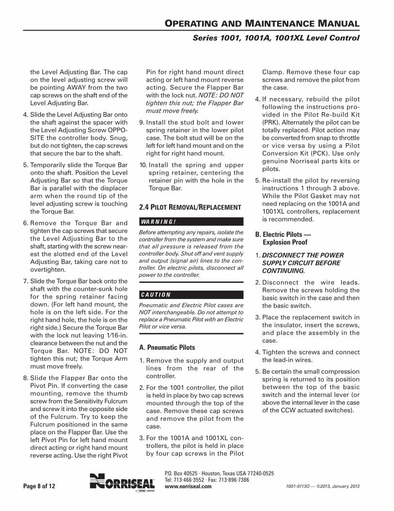
CODE CIRCUITRY ELECTRICAL RATING
“E” EXQ
or
“O” OP-Q
Single Pole Double Throw (SPDT)
UL and CSA Listed:
15 amps, 125, 250 or 450 VAC 0.50 amp 125 VDC0.25 amp 250 VDC
“D” EXD-Q
or
“F” OPD-Q
Double Pole Double Throw (DPDT)
UL and CSA Listed:
10 amps, 125 or 250 VAC0.30 amp 125 VDC0.15 amp 250 VDC
TA B L E 2 — W I R I N G D I A G R A M S
STANDARD SWITCH
Green – Ground
Blue – N.O. 1
Black – Com 1 Red – N.C. 1
Blue – N.O. 2
Black – Com 2
Red – N.C. 2
CODE CIRCUITRY ELECTRICAL RATING
“K” Hermetic
030
Single Pole Double Throw (SPDT)
UL, CSA and FM Listed:
11 amps, 125/250 VAC
5 amps Res, 25 VDC0.50 amps, 125 VDC
“D” EXD-Q
or
“F” OPD-Q
Double Pole Double Throw (DPDT)
UL, CSA and FM Listed:
11 amps, 125/250 VAC
5 amps Res, 28 VDC0.50 amps 125 VDC
HERMETICALLY SEALED SWITCH
Green – Ground
Blue – N.O. 1
Black – Com 1 Red – N.C. 1
Purple – N.O. 2
Yellow – Com 2 Black – N.C. 2
Red – N.C.
Blue – N.O.
Green – Ground

P.O. Box 40525 · Houston, Texas USA 77240-0525Tel: 713·466·3552 · Fax: 713·896·7386 www.norriseal.com1001-0113O — ©2013, January 2013
OPERATING AND MAINTENANCE MANUAL
Series 1001, 1001A, 1001XL Level Control
Page 11 of 12
Pilot output pressure gauge indicates outputpressure signal when fluid level is below displacer on a direct acting controller ORwhenfluid level is above displacer on a reverse actingcontroller.
1. Balance Spring is too compressed and putstoo much pressure on the Torque Bar.
2. The displacer arm is set too high or the dis-placer is hitting something inside the vessel.
1. Back off the spring retainer until the outputpressure signal goes off. Re-check when thefluid level rises (direct acting) or falls (reverseacting).
2. Check the displacer arm by moving the leveling adjusting bar up and down. If theadjusting bar will move in only one direction,this indicates the displacer arm is riding at either the top or bottom of the vessel connection. If it moves too freely, the displacer has become disconnected from thedisplacer arm. Re-center the displacer arm inthe vessel connection.
Pilot output pressure gauge indicates no outputpressure signal when fluid level is above displacer on a direct acting controller ORwhenfluid level is below displacer on a reverse actingcontroller.
1. Balance Spring is insufficiently compressedand doesn’t put enough pressure on the Torque Bar.
2. The displacer arm is set too low or the displacer is hitting something inside the vessel.
1. Compress the spring retainer until an out-put pressure signal is indicated on the out-put pressure gauge. Re-check when the fluidlevel falls (direct acting) or rises (reverseacting).
2. Check the displacer arm by moving the lev-eling adjusting bar up and down. If the adjust-ing bar will move in only one direction, thisindicates the displacer arm is riding at eitherthe top or bottom of the vessel connection.If it moves too freely, the displacer hasbecome disconnected from the displacerarm. Re-center the displacer arm in the vessel connection.
Controller does not repeat at the same fluid levelafter each dump and sometimes fails to eitherdump or shut-off. (The torque bar does notbounce back fast when depressed and appearsto be hard to move.)
Paraffin or debris has built up inside the levelcontrol body.
Remove controller from service and clean outthe body with a solvent.
On interface control, the vessel occasionallyloses all fluid or the vessel overflows, espe-cially with temperature change. The displacerarm is free and the displacer is not hitting insidethe vessel.
The displacer is not big enough to handle theinterface differential. Close specific gravity oftwo fluids and a temperature change can causethis problem.
Provide exact specific or API gravities of bothfluids to Norriseal Engineering for exact sizingof the displacer that should be used..
A Pneumatic Pilot bleeds air continuously. Materia extraña debajo de la bola en un piloto deForeign matter under the ball on a snap controlpilot or under the peanut on a throttle controlpilot.
ORThe tru-arc ring on the snap pilot thrust pin mayhave been dislocated.
Remove the pilot following the instructions inParagraph 2.4. Remove the two cap screwsfrom the bottom of the pilot. Clean the pilotthoroughly. If a Snap Pilot, make sure the dimen-sion between the tru-arc ring and the bottom ofthe pin is 3⁄4 in. If not, gently tap the tru-arcring into the proper location. Reassemble thepilot.
TA B L E 3 . T R O U B L E D I A G N O S I S
PROBLEM SYMPTOM POSSIBLE CAUSE CORRECTIVE ACTION

P.O. Box 40525 · Houston, Texas USA 77240-0525Tel: 713·466·3552 · Fax: 713·896·7386 www.norriseal.com 1001-0113O
OPERATING AND MAINTENANCE MANUAL
Series 1001, 1001A, 1001XL Level Control
Page 12 of 12
H E A D Q U A R T E R S, M A N U F A C T U R I N G P L A N T A N D S A L E S
P.O. Box 40525 • Houston, Texas USA 77240-052511122 West Little York • Houston, Texas USA 77041-5016
Tel: 713·466·3552 • Fax: 713·896·7386www.norriseal.com
Due to the continuous improvement at Norriseal,specifications and/or prices are subject to change
without notice or obligation.
™Envirosave and Norriseal are trademarks of Dover Corporation.
..
.
ABS
Quality
Evaluations, Inc.
Managem
ent System Certi
fication
©2013 Dover Corporation/Norriseal and its affiliates. This manual, including all text andimages, is a copyrighted work of Dover Corporation/Norriseal and its affiliates. It may notbe, in whole or in part, photocopied, scanned, or otherwise reproduced, revised, or publicly displayed, without prior written permission from Norriseal. This manual is for useonly with the new Norriseal valves and/or controllers listed in the manual. It may not be distributed with, and is not for use with, any remanufactured products.
Due to the continuous improvement program at Norriseal, specifications and/or pricesare subject to change without notice or obligation.
All trademarks contained herein are the property of their respective owners.