· web viewtriple jacketed body of stainless steel sheet, inner most jacketed of 16g thick with...
TRANSCRIPT

Technical Specification
Laundry
SNO. DESCRIPTION
1 Washer Extractor.
Heavy Duty High Spin. Computer Controlled. Front Loading,
Open Pocket. Top Suspension With Hydraulic Cushions.
Full Stainless Steel Cabinet. Single Motor Frequency Drive.
5 Compartment Automatic Soap / Chemical Dispenser.
30 kg Capacity, Steam Heated.
2 Washer Extractor.
Heavy Duty High Spin. Computer Controlled. Front Loading,
Open Pocket. Top Suspension With Hydraulic Cushions.
Full Stainless Steel Cabinet. Single Motor Frequency Drive.
5 Compartment Automatic Soap / Chemical Dispenser.
60 kg Capacity, Steam Heated.
3 Drying Tumbler. Front Loading,
Open Pocket. Reversible With Automatic Cool Down Feature.
60 kg Capacity, Steam Heated.
4 Flat Work Drying Ironer.
1 Roll with Heated Chest. Front Feed, Rear Return.
239

Steam Heated,
5 Flat Bed Press.
Auto Timed, Pneumatically Operated.
Head Size : 1500 x 750, Steam Heated.
6 Vacuum Finishing Table.
Table Top Size : 1200 x 750
Electric Steam Iron
Teflon Shoe
7 Dry Linen Trolley.
Overall Size : 1100 x 600 x 1500 ht.
8 Washroom Trolley.
Overall Size : 1250 x 675 x 780 ht.
9 Shelf Trolley.
Overall Size : 1200 x 600 x 1700 ht.
10 Mobile Table.
Table Top Size : 1150 x 750
11 Mobile Table.
Table Top Size : 2350 x 750
12 Laundry Scrub Station with 2 Sinks.
Overall Size: 1600 x 550 x 900 height.
240

13 Supply of Air Compressor, 3 HP Double Stage, 160 ltrs Tank
Recommended.
14 Supply & Installation of Steam Boiler, 500 kg Capacity
along with Water Softener.
241

KITCHEN EQUIPMENTS
1 TEA BOILER
App. Cap.50Ltrs.
S.S.Body, having detachable lid complete with water inlet, outlet heating element of 4.0kw rating with automatic temp. controller
2 TWO BURNER COOKING RANGE
App. Size 1200X600X850mm
Frame work of m.s.anlge duly painted, mounted on s.steel tubular legs with adjustable feet. Top & sides & under shelf of s.s.sheet. The range will be complete with 2nos. Hy-pressure gas burners with individual control valves. Cast iron pan support, GI Sheet constd. spillage collection tray with s.s.handle.
3 EXHAUST HOOD (Without Ducting, Fixing & Extraction fan)
Size 1950x750x600mm
Made of s.steel sheet, 20G thick duly welded & pop rivetted as required. The hood will be complete with s.s.sheet removable type baffle filters. Complete with greese collection channel & greese collection cup/s.
4 WORK TABLE WITH SINK
Size 1500x750x850+150
Top & Sink bowl of s.s.sheet, on s.s.anlge & s.s.tubular frame work with cross bracing at lower portion. Sink bowl will be integrally welded with top & grinded smooth. Sink bowl size 450x450x250mm.
5 TEA COFFEE DISPENSAR
App. Cap. Of Water Boiler 25Ltrs.
App. Cap. Of Milk Boiler 3Ltrs.
Double walled insulated s.s.sheet body having 2 portions. One water boiler fitted with heating element of 2.0kw rating with control switch, indicator lamp & automatci temperature controller. Another portion will be milk boiler portion, fitted inside the water boiler portion. Both the units wiil seprate taps & a removable type s.s.sheet lid with a removable type s.s.sheet drip tray, fixed below the taps.
6. CONVEYOR TOASTER
App.Cap. 100-125 Toasts/hr.S.S.Sheet body, having s.s.sheet conveyor belt. App.225mm wide. The unit will have heating elements on top & lower portion of conveyor belt with variable heat & speed control switch.
7. SANDWICH GRILLER
App. Size of grill plate 250x250mm
242
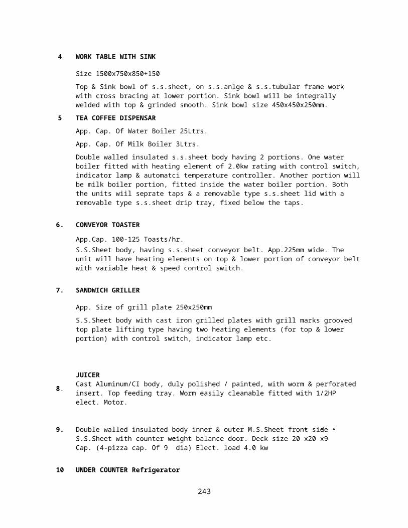
S.S.Sheet body with cast iron grilled plates with grill marks grooved top plate lifting type having two heating elements (for top & lower portion) with control switch, indicator lamp etc.
8.JUICERCast Aluminum/CI body, duly polished / painted, with worm & perforated insert. Top feeding tray. Worm easily cleanable fitted with 1/2HP elect. Motor.
9. Double walled insulated body inner & outer M.S.Sheet front side S.S.Sheet with counter weight balance door. Deck size 20”x20”x9”Cap. (4-pizza cap. Of 9” dia) Elect. load 4.0 kw
10 UNDER COUNTER Refrigerator
Size 1500x750x850mmDouble walled 'PUF' insulated s.s.sheet outer & inner body of s.s.sheet 0.8mm thick having hinged doors with rubber gascuts. Inside s.s.wire shelves on adjustable channel frame complete with 'Kirloskar/Tecumesh' make compressor. Having condensor, can motor & automatic temperature controller etc. Working Temp. (0°c to 5°c)
11 STORAGE RACK
Size 900X450X1800
Vertical of 38 mm dia stainless steel pipe with adjustable feet 5 no vertical at equal distance 1st shelf fixed at 150mm from floor level.
12 DOUGH KNEADING MACHINE
App. Cap of Bowl 50Ltrs.
S.S.Mixing bowl, with s.s.rod/strip mixing arm, mounted on steel tubular & sheet frame work duly painted. Complete with 1.0HP Elect. Motor with control switch.
13 CHAPPATI ROLLING TABLE
Size 1800x900x850mm
Specification same as that of work table
13.1 SUPPORT TABLE
Size 1350X600X850mm
Specification same as above
14 CHAPPATI PLATE CUM PUFFER
Size 1800x900x850mm
Frame work of m.s.anlge, mounted on s.s.tubular legs frame work. All sides pannels & undershelf of s.s.sheet, top plate 10mm thick mild steel with cast iron puffing grills for puffing of chappaties. Complete with 'V' shape LPG burners with individual control valves.
243

15 CHAPPATI COLLECTION TABLE
Size 450x900x850mm
Top tray of 16G s.s.sheet, tray will have App.100mm ht. collor all around, mounted on s.s.tubular legs with adjustable feet & one s.s.sheet undershelf.
16 EXHAUST HOOD (Without Ducting, Fixing & Extraction fan)
Size 1950x750x600mm
Made of s.steel sheet, 20G thick duly welded & pop rivetted as required. The hood will be complete with s.s.sheet removable type baffle filters. Complete with greese collection channel & greese collection cup/s.
17 WORK TABLE
Size 750X750X600mm
Top & undershelf of s.s.sheet on m.s.anlge frame work & s.s.tubular legs, with adjustable feet. Top to have sound deadning material lining as required.
18 TWO BURNER COOKING RANGE
App. Size 1500X750X850mm
Frame work of m.s.anlge duly painted, mounted on s.steel tubular legs with adjustable feet. Top & sides & under shelf of s.s.sheet. The range will be complete with 2nos. Hy-pressure gas burners with individual control valves. Cast iron pan support, GI Sheet constd. spillage collection tray with s.s.handle.
19. SOUTH INDIAN RANGE1500x750x8501mm
Framework made of m.s. angle of size 38x38x5mm and 25x25x5 mm. Top made of 12 mm thick m.s. plate with stainless steel channel for draining the excess oil from fry top. The verticals of the equipment are made of stainless steel of size 38 mm dia and cross bracing. The unit has front panel and side covers upto 300 mm. The unit is provided with ‘v’ shape burners and pilot lamps with independent needle valve controls.
20. EXHAUST HOOD (Without Ducting, Fixing & Extraction fan)
Size 1650x750x600mm
Made of s.steel sheet, 20G thick duly welded & pop rivetted as required. The hood will be complete with s.s.sheet removable type baffle filters. Complete with greese collection channel & greese collection cup/s.
21. LOW HT. TABLE
Size 750x750x600mm
Specification same as that of work table but the table will be without undershelf & will have cross bracing support at lower portion.
22. LOW HT. BURNER
Size 750x750x600mm
Specification same as that of cooking range but the unit will be without undershelf, but will only have cross bracing support at lower portion.
244

23 BULK COOKER
Cap.160Ltrs.
The frying pan will be Of rectangular shaped with 12”depth & a pouring lip & the unit will be fitted with v type high pressure gas burner with control valve & pilot lamp.
24 SUPPORT TABLE
Size 750X900X850mm
Specification same as above
25 BULK FRYER 1500x750x850
Triple jacketed body of stainless steel sheet, Inner most jacketed of 16g thick with 12g thick dish ended bottom, second wall for air gap of 18g stainless steel sheet & outer insulation jacket also of 18g stainless steel sheet. The unit will have counter weight balanced 16g thick stainless sheet lid with insulated handle & fitted with one high pressure gas burner with control valve & pilot lamp the unit will have tilting provision by worm & gear wheel, housed in stainless steel sheet box with rotating wheel front side. The tilting mechanism will be fixed on 50mm stainless steel pipe frame structure with boiler also rating on it the frame work will have grouting provision for floor mounting.
26 EXHAUST HOOD (Without Ducting, Fixing & Extraction fan)
Size 1350x750x600mm
Made of s.steel sheet, 20G thick duly welded & pop rivetted as required. The hood will be complete with s.s.sheet removable type baffle filters. Complete with greese collection channel & greese collection cup/s.
27 PICK UP COUNTER WITH OVERSHELF
Size 1500X750X850+375
Top 3 sides, under & overshelf of s.s.sheet, on m.s.angle & s.s.tubular legs frame work. The counter will have 3 sides fully covered, operator side open. With one undershelf. One overshelf 300mm wide & running along the full length of counter will be provided on top.
28 UNDER COUNTER REFRIGERATOR WITH DOUBLE OVERSHELF
Size 1800x750x850+375+225
29
Double walled 'PUF' insulated s.s.sheet outer & inner body of s.s.sheet 0.8mm thick having hinged doors with rubber gascuts. Inside s.s.wire shelves on adjustable channel frame complete with 'Kirloskar/Tecumesh' make compressor. Having condensor, can motor & automatic temperature controller etc. Working Temp. (0°c to 5°c). The unit will have two ss.sheet overshelves. 300mm wide supported on top by means of s.s.tubular verticals.
TRAY SET UP COUNTER WITH DOUBLE OVERSELFTechnical specification as below
30 TRAY SET UP COUNTER WITH BAIN MARIE & DOUBLE OVERSHELVES
245

Size 1800x750x850+375+225
Top of 16G s.s.sheet, Bain Marie water tank of 18G s.s.sheet, fitted with 3.0kw heating element with automatic temperature controller. Water outlet provision with drain valve, 3 sides covered with 20G s.s.sheet, Top to accommodate s.s.sheet Food Pans with lids & 300mm wide s.s.sheet tray slide on service side (As specified). The unit will be fitted with 375mm & 225mm ht. double overshelves.
31 FOOD TROLLEY WITH 4 ROUND PANS, 1 RICE TRAY & STORAGE BELOW
1350X750X900
S.S.Sheet insulated body, Frame work of m.s.anlge of size 38x38x5mm, mounted on 4 castors (2 with brakes) of size 150mm top to have cutout for 4nos. Round pans for Dal, Subzi etc. with 1 rice tray & storage below. Three side covered with s.s.sheet with s.s.pipe push handle.
32 SOILED DISH LANDING TABLE WITH GARBAGE CHUTESize 1500X750X850mmTop of 16G s.s.sheet with 'Sunkun' top. A garbage chute provided on top with a space below to keep dust bin (Not part of equipment). The top will be mounted on m.s.anlge, rust proof painted & s.s.vertical tubular legs with cross bracing support on 3 sides.
33 POT WASH SINK UNITSize 2400X750X850+150mmTop & 3 sink bowls of 16G s.s.sheet. Duly welded, grinded & polished smooth mounted on m.s.anlge & s.s.tubular frame work with 150mm back splash. Each Sink Bowl Size 500x500x300mm (without sanitory fittings)
34 CLEAN DISH TABLE
Size 1350x750x850mm
Specification same as that of work table but with 2 undershelves.
35 CLEAN DISH RACK
Size 900x450x1800
Vertical of 38 mm dia stainless steel pipe with adjustable feet 5 no vertical at equal distance 1st shelf fixed at 150mm from floor level.
36 WORK TABLE WITH SINK
Size 1000X750X850+150mm
Top & Sink bowl of s.s.sheet, on s.s.anlge & s.s.tubular frame work with cross bracing at lower portion. Sink bowl will be integrally welded with top & grinded smooth. Sink bowl size 450x450x250mm.
37 PRE RINSE SPRAY UNIT
38 HOOD TYPE DISH WASHER
Cap.65Racks/hr.
39 CLEAN DISH TABLE
246

Size 750x750x850mm
Specification same as that of work table but with 2 undershelves.
40 POTATO PEELER
Cap.10Kg./chrgs.
16 gauge Stainless steel sheet peeling drum, lined inside with Abrasive material, stainless steel /cast iron rotating peeling disc. Top of the drum will have a potato inlet door, waste Inlet provision peeled potato discharge door & waste water Outlet pipe. The elect motor of 1.0 hp single phase Compton Or equivalent make, housed in stainless steel sheet enclosure on Suitable rust proof s.s.angle/section iron frame work. (Capacity 10kg/Chargs. )
41 PULVARIOSER (Std.)
Stainless steel sheet body,20g thick. the unit will have A top feeding tray & a housing of stainless steel casting With grinding plates & 3 type of meshes for variable type Of grinding requirements. The unit will be fitted with 1.0 hp single Phase electric motor & will be mounted on 25x25 mm on stainless steelPipe square frame work.cap.30-35 kg/hr.
42 WET GRINDER
Cap.5ltrs (1.0HP)
Stainless steel sheet constd. Body with s.s.sheet constd. Revolving drum, cromium plated pillar support on m.s.angle frame work fitted with electric motor gear box & grinding stones & coconut scraper.
42.1 POT RACK-3 TIER
Size 1500X600X1500mm
Verticals of 38mmX38mm square s.s.pipe, 3 shelves welded with vertical frame of 19mm dia s.s.pipe shelves with equal space between two tubes mounted on adjustable feet.
43 TWO SINK UNITSize 1800X600X850+150mmTop & Sink bowl of s.s.sheet, on s.s.anlge & s.s.tubular frame work with cross bracing at lower portion. Sink bowl will be integrally welded with top & grinded smooth. Sink bowl size 450x450x250mm.
44 VEGETABLE CUTTING MACHINE
Aluminium casted body with ½ hp electric motor safety switch & double feed pusher for round flat & vertical shaped food items etc., the unit will be Table top model with easy to clean provision. Provided with 4 no cutting discs for slicing grating Dicing & French fry cutting attachments.app.100-125 kg/hr.
45 WORK TABLE
Size 1500X600X850mm
Top & undershelf of s.s.sheet on m.s.anlge frame work & s.s.tubular legs, with adjustable feet. Top to have sound deadning material lining as required.
46. STORAGE RACK
247

Size 900X450X1800
Vertical of 38 mm dia stainless steel pipe with adjustable feet 5 no vertical at equal distance 1st shelf fixed at 150mm from floor level.
47. DUNNAGE RACKSize 1200X600X500mm
Made of s.s.square pipes of size 38x38mm, with support of 25mm square s.s.pipe.
48. POT RACK - 3 TIER
Size 1200X600X1500mm
Verticals of 38mmX38mm square s.s.pipe, 3 shelves welded with vertical frame of 19mm dia s.s.pipe shelves with equal space between two tubes mounted on adjustable feet.
49. FOUR DOOR REFRIGERATOR
Size 1200X675X2000mm
Double walled, insulated 'PUF' body made of 0.8mm thick s.s.sheet. Inside chamber to have 4nos. S.s.wire shelves on adjustable channel. The unit will have 4 doors with magnatic rubber gascuts & locking provision. The condensing unit, consisting of 'Kirloskar/Tecumesh' compressor condensor, Air cooled with automatic temperature controller will be fitted on top with ventilation provision. Working temperature (0°c to 5°c)
50. COLD ROOM RACKSize 1650X600X1800mmVertical of 38 mm dia stainless steel pipe with adjustable feet 5 no vertical at equal distance 1st shelf fixed at 150mm from floor level.
51 COLD ROOM RACKSize 1400X600X1800mm
Vertical of 38 mm dia stainless steel pipe with adjustable feet 5 no vertical at equal distance 1st shelf fixed at 150mm from floor level.
52. LPG GAS PIPE LINE
As per Conditions.
248

Canteen equipments
1 HOT & COLD DISPLAY COUNTER Size 1500X675X1200mm
S.S.Body 'PUF' insulated with front side glass & two shelves. The unit will be fitted with Kirloskar/tecumesh compressor, condensing unit, Elect. Motor, Fan etc.
2 BAIN MARIE SERVICE COUNTER
Size 1500x675x1200mm
Top of 16G s.s.sheet, Bain Marie water tank of 18G s.s.sheet, fitted with 3.0kw heating element with automatic temperature controller. Water outlet provision with drain valve, 3 sides covered with 20G s.s.sheet, Top to accommodate s.s.sheet Food Pans with lids & 300mm wide s.s.sheet tray slide on service side (As specified)
3 WORK TABLE WITH SINK
Size 1500X600X850+150mm
Top & Sink bowl of s.s.sheet, on s.s.anlge & s.s.tubular frame work with cross bracing at lower portion. Sink bowl will be integrally welded with top & grinded smooth. Sink bowl size 450x450x250mm.
4 TOASTER
Cap. 24Slices
Double walled, insulated body mode of 20g s/s sheet. The unit will be filled with 2 no radiant heat type spl. designed heating Elements of rating 2.5 kw each with separate Controls. Two no s/s wine slide out tray with Insulated Grips will be provided for keeping Bread slices etc. a slide out s/s sheet drip collection Tray will also be provided under the lower heating Element.
5 SANDWICH GRILLER
App. Size of grill plate 250X250mm
S.S.Sheet body with cast iron grilled plates with grill marks grooved top plate lifting type having two heating elements (for top & lower portion) with control switch, indicator lamp etc.
6 JUICER (table top model)
Cast Aluminum/CI body, duly polished / painted, with worm & perforated insert. Top feeding tray. Worm easily cleanable fitted with 1/2HP elect. motor.
7 TEA COFFEE DISPENSAR
App. Cap. Of Water Boiler 25Ltrs.
249

App. Cap. Of Milk Boiler 3Ltrs.
Double walled insulated s.s.sheet body having 2 portions. One water boiler fitted with heating element of 2.0kw rating with control switch, indicator lamp & automatci temperature controller. Another portion will be milk boiler portion, fitted inside the water boiler portion. Both the units wiil seprate taps & a removable type s.s.sheet lid with a removable type s.s.sheet drip tray, fixed below the taps.
8 UNDER COUNTER REFRIGERATOR
Size 1500x750x850mm
Double walled 'PUF' insulated s.s.sheet outer & inner body of s.s.sheet 0.8mm thick having hinged doors with rubber gascuts. Inside s.s.wire shelves on adjustable channel frame complete with 'Kirloskar/Tecumesh' make compressor. Having condensor, can motor & automatic temperature controller etc. Working Temp. (0°c to 5°c)
9 UNDER COUNTER REFRIGERATOR WITH DOUBLE OHS
Size 1800x750x850+300+225mm
Specification same as sno.8
10 CHAPPATI COLLECTION TABLE
Size 450x600x850m
Top tray of 16G s.s.sheet, tray will have App.100mm ht. collor all around, mounted on s.s.tubular legs with adjustable feet & one s.s.sheet undershelf.
11 CHAPPATI PLATE CUM PUFFER
Size 1200x600x850mm
Frame work of m.s.anlge, mounted on s.s.tubular legs frame work. All sides pannels & undershelf of s.s.sheet, top plate 10mm thick mild steel with cast iron puffing grills for puffing of chappaties. Complete with 'V' shape LPG burners with individual control valves.
12 CHAPPATI ROLLING TABLE
Size 1200x600x850mm
Specification same as that of work table
13 GRIDDLE PLATE
Size 600X600X850mm
Framework made of m.s. angle of size 38x38x5mm and 25x25x5 mm. Top made of 12 mm thick m.s. plate with stainless steel channel for draining the excess oil from fry top. The verticals of the equipment are made of stainless steel of size 38 mm dia and cross bracing. The unit has front panel and side covers upto 300 mm. The unit is provided with ‘v’ shape burners and pilot lamps with independent needle valve controls.
250

14 EXHAUST HOOD (Without Ducting, Fixing & Extraction fan)
Size 1350x750x600mm
Made of s.steel sheet, 20G thick duly welded & pop rivetted as required. The hood will be complete with s.s.sheet removable type baffle filters. Complete with greese collection channel & greese collection cup/s.
15 WORK TABLE
Size 600x600x850mm
Specification same as that of work table
16 DEEP FAT FRYER
Table top model
S.S.Sheet body, having 2 oil pans removable type each Pan Cap. app.8ltrs. With lid, s.s.wire mesh frying basket, lift top type heating element with automatic temperature cotnroller etc.
17. TWO BURNER COOKING RANGE
App. Size 1200X600X850mmFrame work of m.s.anlge duly painted, mounted on s.steel tubular legs with adjustable feet. Top & sides & under shelf of s.s.sheet. The range will be complete with 2nos. Hy-pressure gas burners with individual control valves. Cast iron pan support, GI Sheet constd. spillage collection tray with s.s.handle.
18 WORK TABLE
Size 600x600x850mm
Specification same as that of work table
19 EXHAUST HOOD (Without Ducting, Fixing & Extraction fan)
Size 1350x750x600mm
Made of s.steel sheet, 20G thick duly welded & pop rivetted as required. The hood will be complete with s.s.sheet removable type baffle filters. Complete with greese collection channel & greese collection cup/s.
20 PULVARIOSER (Std.)
Stainless steel sheet body,20g thick. the unit will have A top feeding tray & a housing of stainless steel casting With grinding plates & 3 type of meshes for variable type Of grinding requirements. The unit will be fitted with 1.0 hp single Phase electric motor & will be mounted on 25x25 mm on stainless steelPipe square frame work.cap.30-35 kg/hr.
251

21 WORK TABLE WITH SINK
Size 1500x750x850+150
Top & Sink bowl of s.s.sheet, on s.s.anlge & s.s.tubular frame work with cross bracing at lower portion. Sink bowl will be integrally welded with top & grinded smooth. Sink bowl size 450x450x250mm.
22 STORAGE RACK
Size 900X450X1800
Vertical of 38 mm dia stainless steel pipe with adjustable feet 5 no vertical at equal distance 1st shelf fixed at 150mm from floor level.
23 FOUR DOOR REFRIGERATOR (Vertical model)
App. Size 1200x675x2000mm
Double walled, insulated 'PUF' body made of 0.8mm thick s.s.sheet. Inside chamber to have 4nos. S.s.wire shelves on adjustable channel. The unit will have 4 doors with magnatic rubber gascuts & locking provision. The condensing unit, consisting of 'Kirloskar/Tecumesh' compressor condensor, Air cooled with automatic temperature controller will be fitted on top with ventilation provision. Working temperature (0°c to 5°c)
252

MAJOR OT
Technical Specification of State of Art Modular (OT) Operation Theatre with imported antibacterial steripanel (Made in Germany)
1. Walls made of 10 mm high pressure laminate with both side anti-bacterial (back and front) Steripanel (as per EN standard) and imported. Steripanel with following features : -
non-toxicNo chloride-organic substances Should act against MRSA (Methicillin Resistant Stapyloccus Aureus) which is resistant against antibiotics, commonly found in operating rooms and can be spread by contact of skin.
impact and abrasion resistantscratch proof both side anti-bacterial during the whole lifecycle light and heat resistantwater solvent and chemical resistant stain resistant smooth surface resistant against humidity resistant against disinfective cleaning detergents. Should endure highest Mechanical exposure without visible signs of wear.extraordinary long lastingShould not be dented and / or scratched.No hygroscopic gypsum boards should be used for reinforcement of Steripanel.Should be capable of easy cut if openings for additional electrical outlets, x-ray viewers, etc is required.Panels should be exchangable for revision or replacement at any time.The relevant authority letter from manufacturer is mandatory to avoid duplicacy.
2. Supporting structure required for installing Steripanel on the walls of the operating room should be galvanized steel profile
Pressure relief dampers / Pressure stabilizer.
Pressure relief damper should be of size 300x300 mm with aluminium grill having multi 304 graded stainless steel blades for maintaining the positive pressure inside the operation theatre towards room air pressure.
3. (a) Ceiling system of operating room should be made of SteripaneL (imported and as per EN standard) both side antibacterial and made from 0.8mm thick Steripanel both side with an average weight of 4.5 kg/sq. mtrs. The relevant authority letter from manufacturer must be mandatory.
.
(b) Clean air system with HEPA filters with following
specifications :-
253

The Plenum box should be made of Aluminum Sheet (60601 T5) 1.6mm thick.
System should comprise of thick extruded aluminum profiles frame and sealed gasket.
The Plenum air should pass through “S” class HEPA filters.
The Laminar flow system should have Light Diffusers consisting of two layers of monofilament precision
woven polyester of uniform porosity with an open area of
sufficient resistance to create laminar flow from diffuser
face.
Air should diffuse into the theatre uniformly over the total area,
The range of ventilated ceiling should provide sterility and cleanliness required for OT environment.
Integral lightening should provide an illumination level in excess of 15000 Lux in operating area and 10000 lux in
other area. Electronic stepless dimming down to 5%
without flicker.
Perfect tightness should be guaranteed by an epoxy seal between filters and
holding structure disabling “by pass” of HEPA Filters.
The filters installed in the plenum should be suitable for applications of laminar flow and clean rooms
these filters should meet the following specifications:Protective grids - White epoxy painted micro drawn
grid - Separators continuous thermo plastic chord
Sealant - Polyurethane
Gasket - One piece polyurethane
MPPS average - 99.95% efficiency
3 micron DOP - 99.999% efficiency
Final pressure drop – 600 Pa (Maximum)
Maximum operating Temperature- 60 degree celsius
Maximum RH - 40-50 percent
Efficiency Tests - Filters individually tested and certified
254
4. Conductive floor should be made from two component anti-static resin (imported and of EN standard) in three different layer consisting of primer, self leveling and top layer. Top layer should be treated chemically to harden the surface for longer durability and for ease of cleaning and disinfection. The relevant authority letter from manufacturer is mandatory.
5. Corners should be Imported and made of round shaped aluminum profile which should be integrated into the floor and should be inserted into the wall paneling.
6. Two Number Doors (imported and as per EN standard and
CE marked)
1500mmX2100mm should be automatic sliding should be hermetically sealed should be made of antibacterial high pressure laminate STERIPANEL
should have glass vision window.
The door should meet the following specifications:
i) Doors should conform to BS 7971 Standard.
ii) should have electrical Motor which works on 230 Volts +- 10%
iii) Noise level of movement should not be more than 60 decibel.
iv) Controller should be micro processor based and should be CE marked
v) Power frequency for door should be 50 Hz.
vi) The Door should have 2 Nos. elbow switch, safety photocell and Foot switch.
vii) should have regulateable starting times from 0.5 seconds to 23 seconds.
viii) Maximum starting speed should be 20-200mm/second.
ix) The relevant authority letter from manufacturer is mandatory.
7. Peripheral light (imported and of EN standard ) should have
following features:-
Luminaire body should be dust proof, nearly bacteria proof, high degree of protection IP 65.
255

IP 65 protection rating > dust proof and virtually bacteria proof.
o The meaning of IP 65.o IP: International Protection Ratingo 6: Object size protected against dust tight.o No ingress of dust; complete protection against contact.o 5: Water projected by a nozzle against enclosure from any direction shall have no harmful effects.
Luminaire should be made of highly resistant laminated safety glass which should be 100% shatter protection.
Reflectors should be individually adjustable (± 30 deg) to the conditions in the operating theatre.
It should have no interference on the infrared controls of the operating room.
Endoscopic light : should have green light insert for use in the operating theatre especially for minimally invasive
surgery with low illuminances.
Should have plane glass with stylish fine grained surface for eliminating uncontrolled reflections when
using laser technology.
The body of the light should be completely closed which will prevent the entry of unwanted minute particles from the ceiling into the room thus making it highly suitable for the operating areas.
Switching and dimming of every individual lamp. should have smooth surfaces which is easy to clean and disinfect
The relevant authority letter from foreign principal is mandatory.
8. Ceiling Pendant for Anesthesia (imported and as per EN
standard) should have following features:-
Ceiling pendent should be with spacer block Should have six Medical gas outlet points Should have six electrical Switch & sockets Should have motorized movement. Double Arm pendant should have pneumatic or friction brakes, to avoid unintentional arms movement, with a
minimum carrying capacity of 100 kgs. Mounting and inspection opening should be provided on each end of the arm. Arm should be equipped with a minimum of 1 shelf for holding appliances like cautery/machine,
syringe/infusion pumps, lasers etc. Ceiling interface plate should have interface for gas tubes and electrical connections. The relevant authority letter from foreign manufacturer is mandatory.
9. Ceiling Pendant for Surgeon imported and as per EN
256

standard) should have following features:-
Ceiling pendent should be with spacer block Should have six Medical gas outlet points Should have six electrical Switch & sockets Should have motorized movement. Double Arm pendant should have pneumatic or friction brakes, to avoid unintentional arms movement, with
a minimum carrying capacity of 100 kgs. Mounting and inspection opening should be provided on each end of the arm. Arm should be equipped with a minimum of 1 shelf for holding appliances like cautery/machine,
syringe/infusion pumps, lasers etc. Ceiling interface plate should have interface for gas tubes and electrical connections. The relevant authority letter from foreign manufacturer is mandatory.
10. Ceiling mounted Dual Dome LED OT lights ( imported and
as per EN standard) with following features.
140000 lux, each Dome should have multiple steps dimming, Focus Light field dia - 180-320mm, Colour temp. 4300k, Endoscopy/ Leproscopy green light, Should have minimum 216 LEds, Should have colour rendering Index Ra>93, Should have safety glass, Light emitting surface, Should have satin finish cover glass. Camera – ¼ type Super HAD CCD
Should have atleast 440000 Pixels Should have atleast zoom 72x (18 x optical, 4 x digital), Minimum Lighting should be 1.0 lux, Signal/noise ratio should be 50db Auto Shutter 1/1 to 1/10000 s, 22 levels The relevant authority letter from manufacturer is mandatory.
11. Electric wiring (cable + fittings and fixtures) inside O.T. and
D.B considering following requirements of the operation
theatre.
All high voltage equipments should be in a remote enclosure to allow access to the electrical panel for maintenance without access to the OT area.
Floor should be provided with equipotential earthing. The remote cabinet should house the operating lamp transformer, mains failure relays, electrical distribution
equipment and circuit protection equipment (including leakage current protector, earthing) for all circuits with in OT.
Structured wiring for computers and monitors should be terminated in standard sockets.
257

12. Copper Gas pipe line inside O.T. as per BSEN 13348- 2001STD to cover oxygen, nitrous oxide, compressed air 4 bar and Vacuum. The copper tube should be installed in conformity with HTM 02-01.
13. Membrane type operation control panel should have following facility
a) Should be mounted flush in the theatre wall b) Should have 1 number day time digital clock.c) Should have 1 number elapsed time digital clock.d) Should have 1 number hands free telephone.e) Should have medical gas alarm which should indicate high, normal and low gas pressure for each gas
service present in the operating room.f) Should have temperature and humidity display g) Should have Peripheral light controller.
14. Twin plate x-ray viewing screen which should have
following features
Should be designed to provide a high level of control luminance Should have dimming range 3 – 100% flicker free illuminated by 4 pieces of high frequency fluorescent
lamps.
15. Operating writing list board to be used by surgeon / Anesthesist should be made of high grade G.P. Sheet or powder coated CRC material of size 1000 mm x 700 mm x 60 mm having magnetic properties.
16. Dirty Hatch in operation theatre for removal of OT waste should be equipped with two doors. The doors should be operated electronically.The hatch should be designed in such a way that only one door is open at one time. The Dirty Hatch should comprise of MOC – 18 swg. SS 304, View Panel – 5 mm thick glass on both shutters and with UV light ‘ON’ operational when doors are closed and of size 700 x 700 x 600mm.
258

MINOR/ Emergency OT
Pre Fabricated Stainless Steel Modular Operation Theatre
Item No. Description
1 Providing, Fixing, Supply & installation of Pre Fabricated Modular Operation Theatre with1.5mm Stainless Steel 304 High Grade material with Wall Panel backed with 12mm thick. gypsum with proper supports.
2 Providing, Fixing, Supply & installation of Pre Fabricated Modular Operation Theatre with 1.5mm Stainless Steel 304 Ceiling Panel backed with 12mm thk. gypsum with proper supports.
3 Providing, Fixing, Supply & installation of Filling of all joints & cavities with epoxy filler and sanded flush to provide a seamless finish including one primer and three coats of antibacterial & antifungal paint equivalent to a minimum dry film thickness of 300 microns (imported)
4 Providing, Fixing, Supply & installation , and commissioning of Automatically Operated hermatically sealed Sliding Doors (1500mm wide 2100mm height) complete with glass vision window of 300mm x 300mm with all necessary accessories etc. (imported)
5 Providing, Fixing, Supply & installation , and commissioning of Automatically Operated hermatically sealed Sliding Doors (1000mm wide 2100mm height) complete with glass vision window of 300mm x 300mm with all necessary accessories etc. (imported)
6 Providing, Fixing, Supply & installation, Testing and commissioning of Membrane type Operation Theatre Control Panel (6 service Tiles) mounted flush in the theatre wall with Distribution Board complete with all accessories etc. The control panel comprising of the following :- * 1 no Day Time Digital Clock * 1 no Elapsed Time Digital Clock * 1 no Hands Free Telephone * Medical Gas Alarm ( 5 gas ) * Temperature & Humidity Indicator only * Peripheral Light Control
7 Providing, Fixing, Supply & installation, Testing and commissioning of Proper Pressure Relief Dampers having multi 304 graded stainless steel blades for maintaining the positive pressure inside the operation theatre complete with all accessories etc.
8 Providing, Fixing, Supply & installation of 2mm thick Anti static, conductive
259

dissipative flooring tile laid on a semi conductive adhesive base resistant to mechanical stress and dynamic load and washable.
9 Providing, Fixing, Supply & installation, Testing and commissioning of Recess mounted IP 54 protocol, non-hygroscopic Peripheral Lights for clean room application each set having (2 x 36 watt) compact flurecent lamps and digital dimmable ballast.
10 Providing, Fixing, Supply & installation and commissioning of 3-Bay Scrub station made out of S.S. 304 complete with all accessories i.e. photo sensors with timer & foot switch, thermostatic mixing valve & bypass system etc.
11 Providing, Fixing, Supply & installation and commissioning of Writing Board with magnetic system
12 Providing, Fixing, Supply & installation and commissioning of Two Plate Dimmable X-Ray viewing screen ( Dimming range 3 - 100% Flicker free) ) complete with all accessories etc.
13 Providing, Fixing, Supply & installation, Testing and commissioning of Planair Ceiling system with unidirectional airflow. Plenum unit, Holding structure & Top plenum are made of Aluminium Sheet 1.6mm thk. with aluminum extrusion frame & sealed gasket conforming to DIN 4799 standards for the air distribution system with hepa filter having efficiency 99.97% down to 0.3 micron.. The laminar flow system shall have such design that it provides "S" class Hepa filter . The filter housing terminals are made of a one pice frame and plenum with perfact thightness features. Diffuser : 2 layer monofilament precision woven polyester of uniform porosity with an open area of sufficient resistance to create laminar from diffusers face and inetgral lighting provides an illumination level in excess of 15000 Lux in operating area and 10000 Lux other electronic stepless dimming down to 5% without flicker.
14 Providing, Fixing, Supply & installation, Testing and commissioning of hatch box made out of SS 304 for disposal of dirty linen /waste. Each hatch will be equipped with two doors and the door will be operated electronically. The hatch will be designed in such a way that only one door will be opened at one time. The UV light will be so installed that it is kept on while both the doors are closed, this UV light has to be automatically turned off in case of opening of either of the doors. There shall be indicators on both sides of the OT so that door open/close status can be monitored from the both ends.
15 Providing, Fixing, Supply & installation, Testing and commissioning of Ceiling Mounted Halogen OT Light (imported)
16 Providing, Fixing, Supply & installation of Double arm moveable arm pendent with 750+850mm long arm having weight carrying capacity of 100Kg, eight electrical sockets 5/15 ampere, one monitor shelf and 6 nos. of gas outlets.
17 Providing, Fixing, Supply & installation, of Medical Gas pipeline system inside OT for Oxygen, Nitrous, Medical Air, Vacuum & Electrical wiring within the OT Area with Metal Box, PVC Pipe and fixing of electrical switch & Socket 6/16 amp.
18 Providing, Fixing, Supply & installation of Electrical Distribution board for OT
260

with MCB and Relay card.
Specification of
Curtain Channel, IV hanger from
ceiling system and Nurse Call system.
Electronic Nurse Call System
audio-visual call system a unique 3-colour lamp feature
1.1.1 The System’s Modules should have:-
a. Central Display consoles, for countertop location.b. Alternately, wall-mounted Display Consoles.c. Bed Unit modules, mountable on the wall or a Bed-Head Board Panel.d. Hand held modules, for patient use.
1.2.1 The system Configuration should comprise of a Central Display Console at the nurse –station countertop. This display console should be concerned through cables to every patient bed assigned to the nurse station.
1.2.2 The Bed Unit module should be located on the wall or the bed-head board panel behind each patient’s bed. From this module, a detachable Handset reaches out to the patient through a length of flexible cable.
2. SYSTEM OPERATION
When conditions are normal, the central display console remains dark and the lamps at the bed, handset, door and toilet are lit to show Green to indicate that the system is available and is standing by. The patient should be able to request for a nurse-call by pushing the button on the handset. Whereupon, the lamps at the bed, handset
2.1.1 and door change colour to a blinking bright Red. Simultaneously, the bed number lights up on the central display console, accompanied with a tinkle chime. The nurse can confirm receiving the call by pressing a single common button on the central console. This lights up a Yellow lamp on the handset to reassure the patient that the nurse has heard the call and will attend. The yellow lamp also repeats on the bed, door and toilet to inform that the call has been acknowledged.
261

2.1.2 On completion of the call, the calling line can be Reset only from the bed side, after the nurse has arrived and attended to the patient. Upon its reset, all the display lamp indicators revert to Green.
2.1.3 In case of a delay in attending to the patient, the audible chime should repeat automatically till the patient is attended to.
2.1.4 In case more than one call registers, all pending calls should be simultaneously displayed on the central display console, with the reminder chime repeating till the last patient has been attended to.
3. FEATURES & SPECIFICATIONS
3.1 Central Display Console
The central console with the necessary displays and buttons is housed in a dust and water protected cabinet with an acrylic panel. It has the following features and specifications:
Capacity upto 64 lines in groups of 8, 16, 24, 32, 40, 48, 56 & 64. Electronic digital bed number annunciation displays. Periodic reminder chimes. Distinctive displays for normal calls, emergency & nurse-presence. Single acknowledgement button for calls from all beds. Mains supply input : 230 V +/- 15 % , 50 Hz. System power supply : 12V DC or less. Plug-in type PCB's for easy service and replacement. Under desk terminal box for ease of access & maintenance. Brass screw terminals only - for all incoming line wires. Body & chassis fabricated from epoxy-polyester powder coated aluminium. Dimensions 35 cm W x 35 cm D x 25 cm H, with footprint of 35 x 35 cm.
3.2 Bed Unit Module
Flush mountable on wall or bed-head board / panel. Red, yellow and green solid state LED call status indicators. Single reset button of sturdy micro-switch or membrane switch construction. Epoxy-polyester powder coated aluminium panel with functions marked. Mating connectors or brass screw terminals for incoming wires. Dimensions 15 cm W x 9 cm H x 5 cm D.
3.3 Handset Module
262

Housed in high impact resistant, fluid protected plastic enclosure. Recessed buttons for call initiation. Built in voice functions for patient-nurse intercom option. Flexible cable cord 2.0 meters, with internally detachable bed unit connector. Red, yellow and green solid state LED call status indicators.
Mating connectors or brass screw terminals for incoming wires. Provision for triggering emergency alert with Shower Pull Cord Unit (optional). Dimensions 15 cm W x 9 cm H x 6 cm D.
3.4 Cabling, Conduiting & Site – Preparation
4 Pair UTP data cable of atleast CAT-5 specification to be laid from each bed side to the central display console at the nurse station countertop.
Same as above, from each bed side to the patient room entrance door. Same as above, from each bed side to the room’s attached toilet and shower
stall. Above cables to be enclosed in metal or plastic conduits or casing-capping.
Metal box of size 5” x 3” w/ctc 120 mm for plate mounting holes, to be placed (horizontally) in the wall behind the bed.
263

SPECIFICATION OF
FASTRACK – HOSPITAL
CUBICLE TRACK SYSTEM
Providing, Fabricating and fixing of Hospital Cubical Track System comprising of the following components and specifications:
1) CUBICLE TRACK Made of Metal Aluminum Alloy of Box size 1.7 x 20 x 25mm with 50-60 microns thick powder coating in white color finish. Tracks are bendable to a radius of 300 mm at 90 degree to cover the whole bed.
2) CURTAIN Made of hospital grade premium quality Stain Proof fabric with High quality Nylon Net of 18”
and 24” on top.
3) SUPPORTING SYSTEM OF FASTRACK CONSISTS OF THE FOLLOWING MATERIAL:
Wall Bracket -
Made of CRC steel with white powder coating finish.
i. Bridge Clamp – Made of CRC steel with white powder coating finish.
ii. Roof Suspension – Made of aluminum pipe of 12.5 mm & 19.5mm diameter. The Upper Circular Plate made of aluminum with 50.4mm diameter thickness. These are with white powder Coating (outer surface) finish & are of variable height fixed with the ceiling with anchors, bolts, screws etc.
4) Curtain Removable Point –
Made of SS for simple loading & unloading of curtains.(Also serves as an end hook retainer).
5) Runner –
264

Comprises of wheel type runners made of Teflon for easy and smooth sliding of the curtain.
SPECIFICATION OF
FASTRACK – I.V. TREE SYSTEM
Providing, Fabricating and fixing of I.V. Tree System should comprise of the
following components and specifications:
1) Heavy duty Aluminium track (20mmX 35mm) with white powder coated finish.
2) Heavy duty self looking wheel trolley.
3) Telescopic carrier hanger with length variation option.
4) Five point hanger systems made of SS with 6mm thickness. Four hanger points
with folding provision.
5) Fifth hanger point is fixed right below the carrier for usage convenience.
6) Roof suspension is made of aluminium pipe of 1.5 mm gauge & 25mm/18mm
(adjustable mechanism) with white powder coated finish.
265

CSSD EQUIPMENT
Sr. No.
Equipment
1. Horizontal Rectangular High Pressure High Vacuum Double Door Sterilizer. The sterilizer will be manufactured as per IS:No.3829 (Part 1)-1978 with ISI Mark.
The unit will be designed for operating pressure 30 to 32 psi. and corresponding to a temperature of 134oC.
The sterilizer chamber would be formed out of SS 316. The Jacket will be formed out of mild steel. The jacket outer cover will be of SS 304. The sterilizer will be provided with 2 Nos. pressure locking type hinged doors. The door plate will be of SS 316 with shooting bolts, flush mountings and steam generator will be of SS 304. The stand of the sterilizer will be of mild steel.
The Sterilizer will be automatic with PLC with 5 pre-sets programs and 1 variable program, MMI with Dot-matrix printer wherein date, time, load identification no. cycle selected, cycle parameter including time, temperature and phase etc. can be seen and documented.
Finally, the automation is so designed that once the program is selected then no further intervention is required from the operator till the end of the program.
The sterilizer will also be provided with an intelligent transducer for heater protection
The unit will be complete with vacuum pump and condenser and inter- connecting piping.
Sterilizer as above of chamber size 600 mm x 900 mm x 1500 mm depth (2’x3’x5’) suitable for electrical operation on 400/440 volts, 3 phase, AC supply, Total electrical load 39 KW.
Extra:
266

S.S 316 carriage suitable for any of the above model
S.S 304 trolley suitable for any of the above mode
2. S.S. Control and packing table with drawer, Overall size: 2000mm L x 1400mm W
3. Single Distilled Water Still, generally as per the Barnstead Type. The Still is guaranteed to produce pyrogen free and chemically pure water to comply with IP/BP Standards.
The Still will be manufactured as per “IS:No.3830” and it will also bear the Bureau of Indian Standard Certification Mark.
The evaporator, the multi-baffle and the condenser will be made out of stainless steel with the joints welded. The condenser will be provided with stainless steel tubes, water inlet and outlet connection.
The Water Still will be supplied in a ready to use condition mounted on a suitable stand.
Water Still as above of capacity 20 litres, per hour suitable for electric operation on 400/440 volts, 3 phase AC supply, electrical load being 15 KW.
4. Stainless Storage tank, electric load 6 kw., capacity 120 litres,
5. Washer Disinfector, fully automatic of chamber volume 275 litres, made out of complete S.S 304 suitable for electrical operation on 400/440 volts, 3 phase, AC supply, electrical load 13 KW
6 Drying Cabinet, electric, single door, made out of complete S.S 304, chamber volume 275 litres suitable for electrical operation on 230 volts, single phase, 15 Amps. Electric load 3.6 kw.
7. Ultrasonic Cleaner, electric, capacity 30 litres
8. Stainless steel work table with two sink, overall size 2400mmL x650mm Wx900mm Ht
9. Stainless steel Work Table with bottom shelf, Overall size 1200mm x650x900Ht.
10 Stainless steel table trolley with 2 shelves, overall size 1080x530x800H
11 Glove Washer/E. Cap: 40 pairs ( 80 gloves/charge) as per specification,
267

technical data and drawing 578.
12 Glove Dryer/E. Cap: 40 pairs ( 80 gloves/charge) as per specification, technical data and drawing 579/R
13 Glove Powderer/E Cap: 40 pairs ( 80 gloves/charge) as per specification, technical data and drawing 580.
14 Glove Tester(examiner) – Cap: 200 to 250 gloves/hr. as per specification, technical data and drawing 816 & 817 .
15 Gauze cutting machine with SS table size 900x600x750mm
16 Stainless steel racks with 5 shelves, overall size 130x535x1830mmH
17. Stainless steel Work Table with bottom shelf, Overall size 1525mm x600x900Ht.
18. High Speed High Pressure Horizontal Cylindrical Steam Sterilizer. Operating pressure will be 30 psi. corresponding to a temperature of 134 oC. The sterilizer will be manufactured as per “IS:3829 (Part 2) - 1978” with ISI Mark.
The sterilizer chamber will be formed out of SS 316. The Jacket will be formed out of mild steel. The jacket will be insulated and covered with SS 304. The sterilizer will be provided with one pressure locking type safety door. The door plate will be formed out of SS 316 with shooting bolts, steam generator and flush mounting will be of SS 304. The sterilizer stand will be of mild steel.
The Sterilizer will be automatic PLC based control system with 3 pre-sets programs to minimize human error and ease of the operator. Finally, the automation is so designed that once the program is selected then no further intervention is required from the operator till the end of the program. The sterilizer will also be provided with intelligent transducer for heater protection .
Sterilizer as above of chamber size 400mm dia. x 600mm depth (16” x 24”) suitable for electrical operation, on 400/440 volts, 3 phase, AC supply, electrical load 18 KW.
19. Stainless steel Pass box, size: 600x600x600mm
268

EQUIPMENT FOR TSSU FOR 1 ST FLOOR
1. High Speed High Pressure Horizontal Cylindrical Steam Sterilizer. Operating pressure will be 30 psi. corresponding to a temperature of 134 oC. The sterilizer will be manufactured as per “IS:3829 (Part 2) - 1978” with ISI Mark.
The sterilizer chamber will be formed out of SS 316. The Jacket will be formed out of mild steel. The jacket will be insulated and covered with SS 304. The sterilizer will be provided with one pressure locking type safety door. The door plate will be formed out of SS 316 with shooting bolts, steam generator and flush mounting will be of SS 304. The sterilizer stand will be of mild steel.
The Sterilizer will be automatic PLC based control system with 3 pre-sets programs to minimize human error and ease of the operator. Finally, the automation is so designed that once the program is selected then no further intervention is required from the operator till the end of the program. The sterilizer will also be provided with intelligent transducer for heater protection .
Sterilizer as above of chamber size 400mm dia. x 600mm depth (16” x 24”) suitable for electrical operation, on 400/440 volts, 3 phase, AC supply, electrical load 18 KW.
2. Stainless steel Work Table with bottom shelf, Overall size 915mm x600x900Ht.
3. Stainless steel vertical sliding door, size 500x 500mm opening
4. S.S. Control and packing table with drawer, Overall size: 2000mm L x 1400mm W
5. Stainless steel work table with two sink, overall size 1500mmL x650mm Wx900mm Ht
6. Washer Disinfector, fully automatic of chamber volume 275 litres, made out of complete S.S 304 suitable for electrical operation on 400/440 volts, 3 phase, AC supply, electrical load 13 KW .
7. Ultrasonic Cleaner, electric, capacity 30 litres
8. Drying Cabinet, electric, single door, made out of complete S.S 304, chamber volume 275 litres suitable for electrical operation on 230 volts, single phase, 15 Amps.elec.load 3.6 kw.
9. Stainless Steel Work Table with bottom shelves, overall size: 900 x 600 x
269

900 mm H.
10. Stainless Steel Racks with 5 shelves
EQUIPMENT FOR TSSU FOR 2 nd FLOOR
1. High Speed High Pressure Horizontal Cylindrical Steam Sterilizer. Operating pressure will be 30 psi. corresponding to a temperature of 134 oC. The sterilizer will be manufactured as per “IS:3829 (Part 2) - 1978” with ISI Mark.
The sterilizer chamber will be formed out of SS 316. The Jacket will be formed out of mild steel. The jacket will be insulated and covered with SS 304. The sterilizer will be provided with one pressure locking type safety door. The door plate will be formed out of SS 316 with shooting bolts, steam generator and flush mounting will be of SS 304. The sterilizer stand will be of mild steel.
The Sterilizer will be automatic PLC based control system with 3 pre-sets programs to minimize human error and ease of the operator. Finally, the automation is so designed that once the program is selected then no further intervention is required from the operator till the end of the program. The sterilizer will also be provided with intelligent transducer for heater protection .
Sterilizer as above of chamber size 400mm dia. x 600mm depth (16” x 24”) suitable for electrical operation, on 400/440 volts, 3 phase, AC supply, electrical load 18 KW.
2. Stainless steel Work Table with bottom shelf, Overall size 915mm x600x900Ht.
3. Stainless steel vertical sliding door, size 500x 500mm opening
4. S.S. Control and packing table with drawer, Overall size: 2000mm L x 1400mm W
5. Stainless steel work table with two sink, overall size 1500mmL x650mm Wx900mm Ht
6. Washer Disinfector, fully automatic of chamber volume 275 litres, made out of complete S.S 304 suitable for electrical operation on 400/440 volts, 3 phase, AC supply, electrical load 13 KW .
7. Ultrasonic Cleaner, electric, capacity 30 litres
8. Drying Cabinet, electric, single door, made out of complete S.S 304, chamber volume 275 litres suitable for electrical operation on 230
270

volts, single phase, 15 Amps.elec.load 3.6 kw.
9. Stainless Steel Work Table with bottom shelves, overall size: 900 x 600 x 900 mm H.
10. Stainless Steel Racks with 5 shelves
271

TECHNICAL SPECIFICATIONS GAS PIPELINE
A) OXYGEN SYSTEM
1 OXYGEN MANIFOLD : 12 + 12 COMPLETE WITH 12 NOS. PIG TAIL PIPES
The Oxygen cylinder manifold shall comprise of two cylinders banks which can accommodate 6 ( Six ) number of cylinders each bank complete with copper tail pipes with bull nose fitting of R.H. external threading suitable for cylinder valves conforming to IS:3224( Oxygen service ), and cylinder support system. Manifold is fabricated with high pressure copper pipe of size ½” ID x 15 SWG and high pressure brass fittings made of high tensile brass.
Flexible tail pipes made of copper pipe of ¼” ID and 15 SWG thickness shall be equipped with individual non-return valves to the cylinder manifold for easy removal of cylinders without any disturbance to system operation.
Each manifold shall be provided with a terminal header and a NPT connection for the ACP (Automatic Control panel).
The entire manifold shall be hydraulically tested at 225 Kg/Cm2 pressure, duly degreased for oxygen service, and supplied in sealed cover, ready for assembly at site.
2. EMERGENCY SERVICE: 4 CYLINDERS
It comprises of Single bank of 4 (Six) number of cylinders which shall be connected to the main line through pressure reducing regulator isolating the main control panel to ensure uninterrupted supply of medical oxygen in case main manifold/control panel is inoperative (supplied without cylinders).
3. Fully Automatic Control Panel (For Oxygen Service):
Features:
a) Fully automatic in operation capable of providing flow in excess of 1500 LPM and requiring no action, Automatic Control Panel is pneumatically operated by the service gas and needs no electrical supply to operate. It
272

will continue to function therefore, should there be a failure in the electricity supply. It takes on automatically from the empty cylinder bank to filled cylinder bank.
b) The panel is enclosed in a metal cabinet with a hinged front cover. The cover is fitted with a lock to prevent unauthorised access, and can be swung open for maintenance.
c) A visual indication of the state of the manifold is provided by 3 gauges within the control panel, clearly visible through the transparent cover, these gauges indicate the pressure of the right and left hand banks, and the supply pressure from the control panel to the distribution system.
d) The panel is supplied with sensing facilities to provide visual signals and other ancillary services such as heaters. A heater block is fitted to the inlet pipes for Nitrous Oxide.
e) In addition the panel is fitted with audio alarm indication for changeover of empty cylinder bank to filled cylinder bank.
The entire manifold will be hydraulically tested at 225 Kg/Cm2 pressure, duly degreased for Nitrous Oxide service, and supplied in sealed cover, ready for assembly at site.
NOTE: The above referred system does not comprise the supply of cylinders, which are to be separately arranged by the customer.
B) NITROUS OXIDE SYSTEM
1. NITROUS OXIDE SYSTEM: 6+6 COMPLETE WITH 12 NOS. PIG TAIL PIPES
The Nitrous Oxide cylinder manifold shall comprise of two cylinder banks which shall accommodate 3( Three ) cylinders each bank complete with copper tail pipes with nut nipple fitting of R.H. internal threading suitable for cylinder valves conforming to IS:3224 ( Nitrous oxide Service), and cylinder support system.
273

The copper tail pipes are fitted with individual non-return valves to the cylinder manifold for easy removal of cylinders, without any disturbance to system operation.
Each manifold will have one terminal header and a NPT connection for the Automatic Control Panel.
NOTE: The above referred system does not comprise the supply of cylinders, which are to be separately arranged by the customer.
2 EMERGENCY SERVICE – 2+2 CYLINDERS
It Comprises of Single bank of 2 cylinders which shall be connected to the main line through Pressure Reducing Regulator isolating the main control panel to ensure uninterrupted supply of Nitrous Oxide in case main manifold/control panel is inoperative (supplied without cylinders).
3. AUTOMATIC CONTROL PANEL (Nitrous Oxide service):
Same as above at sl.no.3 (a) to (e) including provision of heating system for raising the temperature for Nitrous Oxide.
C) COMPRESSED AIR SYSTEM
The Medical Compressed Air System would consists of 2 Nos. Air Compressors with Electric Motor, Electrical Switch Gear and Automatic Control System, Air Receiver, No-het Air Dryer, Pressure Regulator-cum-filter, Interconnecting piping with necessary valves and fittings thereof.
Specifications:
a) Air Compressor : 2( Two ) Nos. Type : Reciprocating, Non-lubricated
Double stage. Capacity : 57.18 cfm at 9 Kg/Cm2. Cooling : Air cooled.
b) Drive Electric Motor : 2 ( Two ) Nos.
274

Motor : 15 HPType : Induction Motor, TEFC.Speed : 1440 rpm (syn.)Drive : Belt drive.Electricity supply : 440 Volt, 50 Hz. 3 phase.
c) Starter : over load protection.d) Air Receiver 2000 Ltrs.e) Air Dryer 60 cfm
Air Compressors are mounted on base frame. The Compressor shall discharge into the after cooler, moisute separator and then to the air receiver. The Air Receiver is connected to inlet of the Air Dryer and outlet is connected to the hospital pipeline system through pressure regulator-cum-filter. The compressor are air cooled..
2. Ultra Filter & reducing system
D) VACUUM PUMP SYSTEM
1.1 The Vacuum System shall consist of two vacuum pumps with motors, electricals switchgear & automatic control system, one number vacuum reservoir, and interconnecting piping, air filters, valves & fittings thereof.
Specification:
a) Vacuum Pump : 2 Nos. Type : 7V, reciprocating, single stage.Capacity : 110 cfm ( 3144 lpm). Vacuum : 737 mm Hg.Cooling : Air Cooled.Starting : Unloaded.
b) Drive Data
275

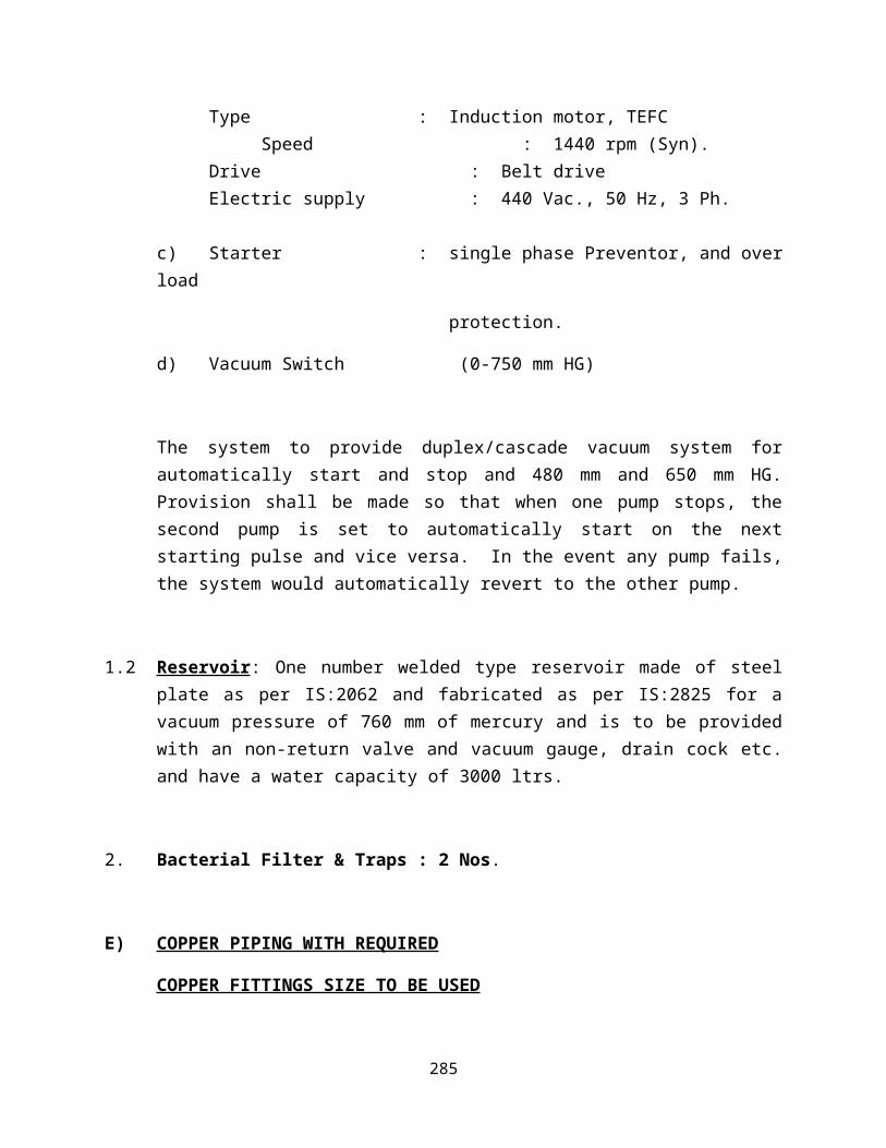
Motors : 2 Nos.Capacity : 7.5 H.P.Type : Induction motor, TEFC
Speed : 1440 rpm (Syn).Drive : Belt driveElectric supply : 440 Vac., 50 Hz, 3 Ph.
c) Starter : single phase Preventor, and over load
protection.
d) Vacuum Switch (0-750 mm HG)
The system to provide duplex/cascade vacuum system for automatically start and stop and 480 mm and 650 mm HG. Provision shall be made so that when one pump stops, the second pump is set to automatically start on the next starting pulse and vice versa. In the event any pump fails, the system would automatically revert to the other pump.
1.2 Reservoir: One number welded type reservoir made of steel plate as per IS:2062 and fabricated as per IS:2825 for a vacuum pressure of 760 mm of mercury and is to be provided with an non-return valve and vacuum gauge, drain cock etc. and have a water capacity of 3000 ltrs.
2. Bacterial Filter & Traps : 2 Nos.
E) COPPER PIPING WITH REQUIRED
COPPER FITTINGS SIZE TO BE USED
PIPING MATERIAL
1.1 Piping: All pipes shall be drawn half hard temp., solid drawn, seamless, phosphorous deoxidised, non-arsenic and degreased copper pipe conforming to
276

BS 2871-1971 Part 1 (Table X) and chemical compositon as per BS-6017 of 1981 table 2.
The supplies of copper pipe (Mexflow) would be accompanied with manufacturers test certificate for the physical properties of copper pipes and their Chemical composition. The supply of pipes be further substantiated with inspection certificate from the third party like SGS/Lloyds Register.
The Pipeline will be laid as per HTM-2022 of UK Specification.
Supply to the following sizes of pipe:
i) 76 mm outer dia, 1.2mm thick.ii) 54 mm Outer Dia, 1.2mm thick.iii) 42 mm Outer Dia, 1.2mm thick.iv) 28 mm Outer Dia, 0.9mm thick.v) 22 mm Outer Dia, 0.9mm thick.vi) 15 mm Outer Dia, 0.9mm thick.
vii) 12 mm Outer Dia, 0.7mm thick.
1.2 Fittings: All copper fittings shall be as per BS 864 for the copper pipeline.
Connections for outlet points and zonal/isolation valves are Brass.
Copper pipes would be secured to wall with LDPE saddles or to ceiling fixed MS bracket wherever necessary.
1.3 Brazing: For copper joints, brazing material to be used will be silver-copper phosphorous alloy which shall be used without flux.
For copper to brass joints 43% silver brazing rods with flux would be used.
Flow of nitrogen gas would be provided to avoid oxidization inside the pipeline during brazing.
2. FABRICATION
2.1 Cleaning: Before putting for erection all pipes, valves and fittings are cleaned and degreased.
2.2 Pipe and tube joints:
277

For copper fittings in the copper pipeline, the brazing for copper joints shall be done without using flux and the material for jointing used will be silver-copper-phosphorous alloy.
For brass joints for jointing outlet points and area/zonal valves material used is 43% silver brazing rod with specified flux.
For installation of equipments threaded connections equipped with nut, nipple & adoptors are used.
2.3 Bends:
All bends are made of copper pipe of higher dia than the pipe requiring change of direction and these bends will be made out of thicker size pipe to avoid thinning and flattening at any point.
2.4 Erection:
The erection of the copper pipe shall be done only after cutting the pipes to size as per site requirements. It does not leave any scope for springing.
2.5 Supports:
To avoid weight of the pipe on the joints supports ( saddles made of LDPE material) are provided at a distance of every 4-6 feet as prescribed by HTM-2022.
3. TESTING
3.1 Blowing:
After erection all the pipes are blown with nitrogen or compressed air. This blowing of the pipeline with nitrogen or compressed air under pressure clean the pipeline thoroughly.
3.2 Joints tests:
The entire pipeline after erection is put to test for checking leakage of brazizng joints at a pressure twice the working pressure for 48 hours. In case of drop in pressure the joints are examined with soap solution.
3.3 Final test:
278

After repairing the joints in case leakages are found, the pipeline shall again be put to test with Comprssed Air/Nitrogen at twice the working pressure for 48 hours and then thereafter entire pipeline will be flushed with Nitrogen & tested with specific gas for Anticonfusion Tests.
4. PAINTING
4.1 All pipes after laying shall be painted as per colour specification “IS CODE” 2379:1963 amended 1990.
F). VALVE WITH VALVE BOX AND PRESSURE GAUGE
The valve boxes would be made of Zinc coated Mild Steel and shall be powder coated for housing area/zonal valves. The valve box would be lockable having glass cover.
G) FLOOR ISOLATION VALVE
Valves shall be degreased and full bore ball type. Valves shall require only a quarter turn of the handle to completely open or close and would be cleaned for oxygen service.
H) AREA LINE PRESSURE ALARM
1 Line Pressure Alarm Panel for Medical Gas Piping System:
The microprocessor based audio-visual area alarm panel would be closed circuit, self monitoring and self contained type and designed to monitor the following indications:
For Operation Theatres For Other Areas
Oxygen : High/Low/Normal Oxygen : Low/Normal
Nitrous Oxide : High/Low/Normal Nitrous oxide : Low/Normal
Compressed Air : High/Low/Normal Compressed Air : Low/Normal
Vacuum : Low/Normal Vacuum : Low/Normal
279

The alarm system assembly would comprise of proper sensing device to sense the condition of the system pressure.
The panels shall have inscribed lumininous facias with flasher and alarm complete with flush-cancel, alarm-mute, fault reset and lamp test buttons. All lamps shall be long life LED type with perspex facias with approved incriptions. The microprocessor based alarm annunciator is equipped with solid state plug in type circuit board and an integral step down transformer. The LED indicator fitted integral step down transformer. The LED indicator fitted within the annunciator are rated for more than one lakh hours. The alarm will be complete in all respect fitted with remote sensing switches.
The alarm system would be equipped with microprocessor chips and the alarm annunciator.
All AAP’s shall be self contained low voltage with its own transformer, pressure sensors etc.
2. PRESSURE SWITCH
2.1 Pressure switch for High & Low pressure signals:
Pressure switches as sensing devices in audio visual alarms for Oxygen, Nitrous Oxide & Compressed Air System. Pressure switches are equipped with NO/NC contacts. These are properly cleaned & fit for use with medical gases. These would be used with 220V Ac electric supply & have a rating upto 15 Amps, tested with 100 & 200 PSIG pressures.
The pressure switch constructed of a rugged cast, weather proof housing with mounting bracket, and a ¼” BSP gas service line connection at the bottom of the assembly.
2.2 Vacuum Switch: Vacuum switches used to make cut in or out connections on either increasing or decreasing vacuum. These would be cleaned for use with medical gases & have a adjustable range upto 29” of mercury vacuum. It has both NO & NC contacts & fit for use with 230V electric supply.
The vacuum switch constructed of a rugged cast, weather proof housing with mounting bracket, and a 3/8” BSP gas service line connection at the bottom of the assembly.
280

I) OXYGEN FLOWMETER
Back pressure compensated oxygen flowmeter ( 0 to 15 lpm) attached with humidifier bottle. Flowmeter made of Lexan Shroud and humidifier bottle made of polycarbonate. Both unbreakable and autoclavable.
J) GAS OUTLET POINTS (IMPORTED)
Terminal/Gas Outlets as per HTM-2022
Gem 10 Terminal Unit:
The medical gas terminal units shall conform to EN 737-1:1998 and accept probes to BS5682:1984. Terminal units shall be capable of single-handed insertion and removal of the medical gas probe. The anaesthetic gas scavenging (AGS) terminal unit shall conform to BS6834:1987. The wall mounted first fix assembly shall consist of brass pipeline termination block with copper stub pipe secured between a back plate and a gas specific plate to allow limited radial movement of the copper stub to align with the pipeline. The gas specific plate shall be permanently fixed to the backplate by means of tamperproof screws locked in position with an anaerobic curing adhesive. The first fix shall incorporate a maintenance valve (except for vacuum) and a test plug. The test plug shall provide an effective blank to enable carcass pressure testing. The second fix plastic components shall be manufactured with the pin index permanently moulded into the gas specific socket. The socket assembly shall retain a capsule assembly, containing the check valve and probe “O” Ring seals. The replaceable capsule assembly shall enable all working parts subject to wear through usage to be replaced as a factory tested assembly, thereby reducing maintenance time. Each termination block assembly shall be pressure tested by the pressure decay method.
281

Gas Specificity:
Terminal units shall be specific and only accept the correct medical gas probe. Gas specific components shall be pin-indexed to ensure that a correct gas specific assembly is achieved so that in normal course of dismantling for repair or maintenance, parts from other gases cannot inadvertently be used. Wall mounted terminal units shall incorporate an anti-rotation pin to engage with connected downstream medical equipment ensuring correct orientation
Materials
All screws, probe roller pins, locking springs and the anti-rotation pin shall be manufactured from stainless steel. The second fix assembly shall be incorporate three injection moulded parts in fire-retardant nylon 66. All wetted parts (except seals) shall be brass or copper. Copper stubs pipes shall be manufactured from phosphorous de-oxidised non-arsenical copper to EN 1412:1996 grade CW024A, manufactured to metric outside diameters in accordance with EN 13348:2001R250 (half hard). All elastomeric seals shall be manufactured from Viton with a Shore hardness of 75.
Pipeline Connections:
Terminal units installed in walls, bedhead trunking, headwalls or fixed pendants shall be connected to the pipeline with a copper stub pipe. Pressure gases and vacuum shall incorporate a 12mmcopper stub pipe with a swaged nend for direct connection to a 12mm O/D copper tube without the need for an extra fitting, thereby requiring only a single brazed joint to be made. Terminal units for anaesthetic gas scavenging shall incorporate a 15mm O/D copper stub pipe.
Terminal units installed in booms or moveable pendants shall be attached to their respective flexible gas hose by a gas specific non-interchangeable screw thread (NIST) fitting to BS EN 739:1998. Terminal units shall be fitted with a male NIST and nut for connection to hoses with a female NIST connection.
282

Performance:
Pressure drops across the terminal unit shall comply with clause 6.3 of EN 737-1:1998. The flow/pressure drop characteristics for the Gem 10 are shown below with the maximum allowable value from EN 737-1:1998 shown in parenthesis.
NominalPressure
(kPa)
TestPressure
(kPa)Flow
(l/min)EN 737-1Limit(kPa)
Gem 10(kPa)
400 320 60 15 1.18400 320 200 70 23.14700 640 300 70 43.57
Vacuum *40 40 15 6.57* Absolute pressure
K) WARD SUCTION UNIT WITH REGULATOR
Consisting of one no. Suction Regulator connected with 2000 CC / 1000 CC / 600 CC pot of collection. The jar and the lid are made of polycarbonate which are autoclavable and unbreakable. The jar is fitted with an overflow safety trap & the regulator fitted with an ON/OFF valve and a knob to regulate the online suction.
L) THEATRE SUCTION TROLLEY UNIT WITH REGULATOR
It is equipped with two polycarbonate jars of 2000 CC each having lid and float assembly. Mounted on a dormodule type trolley fitted with free running castors. It would be fitted with a vacuum regulator, gauge and overflow safety trap and a three way valve to control the suction either in left jar/right jar/both the jars.
M) HIGH PRESSURE TUBE
283

High pressure hose colour coded for gas / vacuum specific would have antistatic properties as per ISO Specifications.
N) MASTER ALARM 16 WINDOW
To provide audio visual, close circuit MICROPROCESSOR based self monitoring type Master Alarm with following indications:
Oxygen : High/Low/Normal
Nitrous Oxide : High/Low/Normal
Comp. Air : High/Low/Normal
Vacuum : Low/Normal
The panels shall have inscribed luminous facias with flasher and alarm complete with flush cancel, alarm mute, fault reset and lamp-test buttons. All lamps shall be long-life LED type with perspex facias with approved incriptions The microprocessor based alarm annunciator is equipped with solid state plug in type circuit board and an integral step down transformer. The LRF indicator fitted within the annunciator are rated for more than one lakh hours. The alarm will be complete in all respect fitted with remote sensing switches.
The alarm system offered by us is equipped with microprocessor chip and the alarm.
O) ELECTRICAL CONTROL PANEL EQUIPPED FOR DUPLEX & CASCADE SYSTEM FOR COMPRESSOR & VACUUM PUMP
Electrical control panel is made of MS Sheet having thickness 16 SWG and should be apoxy powder coated. The electrical control panel would be equipped with auto manual selector, 2 nos. Star-Delta starters each compatible to 15 HP motors for compressors and 2 nos. DOL starters compatible to 7.5 HP each electric motor for Vacuum pumps.
The electrical control panel would be further equipped for duplex/cascade system for vacuum pumps & Air Compressors and also be equipped with safety
284
equipment for the air compressors. Safety equipment for air compressors would include temperature controller, temperature indicator.
285

OXYGEN PLANT
1. INTRODUCTION
This technical proposal describes the engineering and hardware supply for a PSA Oxygen High
Purity Generator, Type MSO 650 PSA
The whole plant is skid mounted, and containerized which allows an easy and quick installation on site. It reduces also the required start-up time.
Utilities required are electricity and cooling water during normal operation of the plant.
The High Purity MSO 650 PSA type gas generators have a compact footprint including all equipment and utility systems.
2. DESIGN BASIS
2.1 UNITS
The following units are used in this proposal:
Temperature 0C
Pressure, absolute Kg/cm2(a)
Pressure, gauge Kg/cm2(g)
Weight Kg
Volume, gases Nm3 at 00C and 1.033 Kg/cm2
Volume, liquid m3 at 150C
Flow, gases Nm3/hr
Flow, liquid m3/hr
Energy/Power Consumption kWh
Power kW
Force N/m2
Conductivity S/cm
2.1 PERFORMANCE DATA
The following data is used as a basis for design. If not stated otherwise, they are subjected to a
general tolerance of 5%. Guaranteed values are stated in relevant of this proposal.
286

2.2 PLANT GENERAL DATA
Turn Down 40-100 %
Plant operation Automatic
Plant Running Continuous
Plant Mounting Skid Mounted
Plant Location Indoor
2.3 PRODUCT GAS COMPOSITION
Flow 650 LPM
Pressure, min. 4 Kg/cm2 at plant
After Booster 150 Kg/cm2 for cylinder bank
Nitrogen 5 %
Hydrogen 0 %
Oxygen 95 %
CO2 + Balance Inert Gases Traces
Moisture Atm. Dew Point of (-) 50 0C
Oil content 0.1 PPM
Suspended Particles <0.03 Microns
Temperature, approx. Ambient2.4 UTILITIES REQUIRED
2.4.1 POWER
Voltage 415 V
Phase 3
Frequency 50 HZ
Compressor
(Screw) 55 kW
Water Pump 3 kW
Fan Motor of
Cooling Tower 1 KW
287

Refrigerated Unit 3 KW
Gas Booster 15 KW
Net Connected load 77 KW
Average Power
Consumption 1.30 KWh/M3 of gas produced
2.6 SITE CONDITIONS
Installation Outdoor
Ambient temperature, max. + 45 0C
Ambient temperature, min. - 5 0C
Wind Load, max. 650 N/M2
Snow load, max. 1000 N/M2
Design temperature for
basic and detail engineering 40 0C
Hazardous area classification
Outside battery limit None
Other atmospheric conditions Normal humidity, normal urban dust concentrations
2.7 EQUIPMENT NOISE LEVEL
Noise level as an 8-hour time-weighted average is less or equal to 75 dB(A) at 3 M distance from battery limit.
3. PLANT AND PROCESS DESCRIPTION
The MSO 650 PSA is designed for an automatic and unmanned operation. Start, stop, normal and partial load operation as well as an emergency shut down are automatically controlled and guarded by the control system.
Personnel supervision is reduced to regular visual inspections and maintenance work within defined intervals according to the operations and maintenance manual.
The complete system is PLC based. The integration of the system is very simple as only power and water connection is al to be done, apart from connecting the product gas line to consumption point.
The complete plant is workshop assembled and tested before delivery. Thus, installation on site is reduced to placing the plant skid on prepared hard plain surface, mounting the product pipeline to consumption point and supplying the electrical and water interface.
3.1 PROCESS DESCRIPTION
288

Please refer to the attached Process & Instrumentation Diagram. All service prone equipments are covered with one working and one standby modes so that at no time the supply of gas is being affected.
Cooling Tower and Pumping Station
A cooling tower of 10 TR is being considered with one working & one stand by water pump is used so as to feed the cooling water to the system required for the plant at different stages.
Air Compressor Unit
The air compressor shall be Screw lubricated, Air Compressor, suitable for continuous service. It shall deliver air at 5 kg/cm2 (g) pressure. Again one working and one standby compressor has been used to meet any eventuality.
Water -to-Air Heat Interchanger
The compressed air temperature shall be reduced with the help of a heat interchanger, which shall be Shell and Tube construction.
This is also in one working and one standby mode.
Air Receiver
For regulating / minimizing surge in compressed air, a wet air receiver is installed, so as to dampen
the pulsation, if any of the air compressor.
Filtration Unit
The compressed air shall then be passed through a Pre-Filter based on Sintered Bronze element,
suitable for filtering physical moisture and pollutants to a level of 0.1 micron.
The arrangement is one working and one standby mode.
Refrigerated Air Drying Units
To remove the moisture from air before entering to the PSA Module for generation of oxygen and also to remove moisture load on Zeolite Molecular Sieves a Refrigerated air dryer is being used to remove moisture from compressed air.
The system consists of air to air heat exchanger, a Hermetically sealed compressor, a hot gas
bypass valve, an expansion valve, A LP/HP cutout, a sight glass, a condenser, a dryer, Freon gas and interconnecting piping.
The arrangement is again in one working and one standby mode.
PSA Module
The air now enters to the PSA adsorbers filled with activated alumina at the bottom and Zeolite
molecular sieves (ZMS) above the alumina bed.
289

This module is known as PSA Module and interconnected with 8 nos. of automatic changeover
valves & having a time cycle of 1+1 minute. For 1 minute one tower goes for adsorption i.e. under production of Oxygen of 95% purity whereas the other one goes under regeneration process to beprepared for the next cycle.
Vessel
After the adsorbers a Oxygen surge tank has been provided to provide saturated Oxygen gas with the required maximum oxygen content of 95%.
Following shall be the Oxygen parameters at the outlet of PSA Module, which is the product gas:
Flow 650 LPM
Pressure 3.0 Kg/cm2 (g)
Nitrogen 5 %
Oxygen 95 %
Moisture Atm. Dew Point of (-) 50 0C
Temperature, approx. Ambient
Product Oxygen Flowmeter
Flow of Oxygen is measured by installing a rotameter. The gas shall now be sent to the storage
vessel.
Product Oxygen Line
A backpressure regulator is provided in the product Oxygen line, to maintain constant downstream pressure in the PSA Oxygen gas generator followed by a 3-way vent valve. 3rd port of the vent valve is interlocked with the on line oxygen gas analyzer (Separate Price quoted) and is so set that no amount of unwanted impure Oxygen flows to the storage tank.
On-line Percent Oxygen Analyzer
The product Oxygen is analyzed online on continuous basis, with the help of an on-line oxygen
analyser. The analyser is interlocked with a 3-way vent valve before the storage vessel, which shall vent impure Oxygen till the purity is within the set limit.
Oxygen Gas Storage System (Low Pressure)
We are offering to supply to you 1 No 5 M3 geometrical volume water capacity Oxygen Gas Storage Tank, designed for an operating pressure of 4 Kg/cm2g, so as to store 20 NM3 Oxygen gas.
Gas Boosting Station
A booster has been used further to boost the gas so as to fill in gas cylinders (client’s scope) so as to able to supply at various places where pipe line for oxygen is not being laid or not even
290

possible to lay.
The booster is 3-stage and can boost the gas up to 150 Kg/cm2 pressure.
Oxygen Gas Cylinders Storage System
We are offering to supply to you a header of 10 + 10 cylinders which can be filled with the help of gas booster.
The required battery of cylinders shall be in scope of client.
4.0 ENGINEERING SCOPE OF SUPPLY
Shall be carry out all engineering work required to supply equipment, which meets the
performance data as specified in section 2, and guarantees of relevant section.
Services that are marked as “optional” are not part of the scope of supply and have to be ordered separately.
4.1 BASIC AND DETAILED ENGINEERING
The engineering of the equipment as specified in Section 5 of this proposal mainly consist
of the following works:
Process and mechanical design
Specification of the equipment and materials
Procurement and Order expediting
Inspection of equipment and materials
Fabrication and fabrication supervision
Mechanical and Electrical workshop test
Generation and supply of documents
Erection and commissioning supervision (optional)
4.2 DOCUMENT SUPPLY
The below specified documents will be supplied to the customer within the specified times.
Documents, which require customer’s approval, shall be returned after inspection within 10
working days from their receipt.
Document 1st Issue Final Issue
(weeks after receipt of order)
Time Schedule 1
291
P&I Diagrams, Process 1 As built
Plant layout 2 As built
Foundation Loading plan 2 As built
Operations Manual With Plant
List of recommended spares With Plant
5.0 GENERAL SCOPE OF SUPPLY AND EXCLUSIONS
SCOPE OF SUPPLY
1. FRP Cooling Tower of 10 TR capacity with fan motor.
2. Cooling water pumps in one working & one standby mode of suitable capacity.
3. Screw type Air Compressor Set as feed air compressor, complete with Electrical motor,
Starter, Instruments and accessories in one working and one standby mode.
4. Shell & Tube type heat exchanger in one working & one standby mode.
5. Wet air receiver with mounting & fittings.
6. Set of Pre-Filter in one working and one standby mode.
7. Refrigerated type air drying unit with interconnecting valves and instruments as per P & I
diagram in one working and one standby mode.
8. PSA Oxygen module interconnected with valves, instrumentation & piping as per P & I
diagram. The set of valves are in one working and one standby mode.
9. First fill of Zeolite Molecular Sieves.
10. Surge Vessel with instrumentation and accessories.
11. Rotameter with by pass arrangement in Product Oxygen line.
12. Back pressure controller & vent valve in Product Oxygen gas line.
13. Centralized Electrical Control panel with one working and one standby PLC.
14. Interconnecting piping, instrumentation etc.
15. On-line Percent oxygen gas analyzer.
16. Oxygen storage tank of 5 M3 geometrical Volume designed for operating pressure of 4
Kg/cm2g complete with mounting, fittings, pressure switches etc.
17. 3–stage Gas Booster with its driving motor, 10 + 10 cylinders header and necessary
292

instrumentation.
18. Two coats of red oxide prior to dispatch & Painting of the equipment at site.
19. Painting of plant as per requirements.
20. Necessary cabling of the equipments.
21. Earthing of equipments.
22. Documents as per schedule.
23. Erection, commissioning and necessary training of equipment before handing over.
EXCLUSIONS
1. All parts and services not expressively mentioned in our offer.
2. Piping outside battery limits
3. Procurement of all permits required for erection, commissioning and operating of the plant
at site.
4. Unskilled Labor.
6.0 BOUGHT OUT COMPONENTS
Following is the list of the major bought out components of the equipment offered to you. Discussions in pre order stage is welcome and suitable changes shall be made as per clients choice for the makes of the bought outs.
AIR COMPRESSOR : ATLAS COPCO / IR / CPT
ELECTRIC MOTOR : SIEMENS / CROMPTON
COOLING TOWERS : PALTECH
WATER PUMPS : KIRLOSKAR
FILTERS : ULTRA FILTER, USA
ZEOLITE MOLECULAR SIEVES : CECA, FRANCE / UOP, USA.
CHANGE OVER VALVES-PSA : GEMU, GERMANY
SOLENOID VALVES : ROTEX
PRESSURE SWITCH : DANFOSS
PRESSURE GAUGE : MASS
PRESSURE REGULATOR : SHAVO NORGREN
ACTIVATED ALUMINA : ACE, VADODRA
293

ISOLATION VALVES : AUDCO, L & T / BDK
ROTAMETER : I.E.P.L
TEMPERATURE CONTROLLER : HONEYWELL
OXYGEN ANALYSER : SERVOMAX, U.S.A.
BACK PR. CONTROLLER : NIRMAL
VENT VALVE : GEMU / AIRMAX
ELECTRICALS : SIEMENS
PLC : SIEMENS / GE FANUC
SAFETY VALVE : SEBIM / ANIL ENGG
GAS BOOSTER : ICL
7.0 SAFETY FEATURES
7.1 SAFETY INSTRUMENTS
a) Low water level in cooling tower.
b) Low oil level switch on feed air compressor.
c) Safety valve on air receiver.
d) Low Pressure Switch on air receiver.
e) High Temperature Switch on air receiver.
f) Low cooling water pressure switch on cooling water line.
g) Safety valve on Oxygen surge vessel.
h) Low pressure switch on Oxygen surge vessel.
i) Automatic vent valve at Oxygen surge vessel outlet.
j) Oxygen Analyser and high oxygen interlock on Oxygen surge vessel.
k) Low pressure suction pot of gas booster.
l) High pressure gas booster discharge.
m) High pressure switch storage tank.
n) Safety valves on storage tank.
7.3 AUDIO VISUAL ALARMS
Following audio-visual alarms shall be displayed on the annunciator on the main control
294

panel :
1. Low Pressure in air receiver.
2. Low pressure water.
3. High temperature air.
4. Low Pressure in Oxygen surge tank.
5. Oxygen content high.
6. Low pressure suction pot.
7. High pressure Booster discharge
8. High Pressure in Storage Vessel.
8.0 DETAILS OF EQUIPMENT OFFERED
8.1 COOLING TOWER WITH PUMPS
No off 1 No.
Type Induced cooling
Capacity 10 TR
No. of Water Pumps 2 Nos.
Motor rating of water pump 3 KW each
Motor rating of Fan motor 2 KW
8.2 AIR COMPRESSOR
No off 2 No.
Motor rating 55 KW
Free Air Delivery 345 CFM
8.3. AIR RECEIVER
No off 1 No.
Code of Construction IS 2825
Material of Construction IS 2062
Design Pressure 5 Kg/cm2 (g)
Design Temperature 65 0C
Shell/Dish Thickness 6/8 MM
295

Geometrical Volume 800 Liters
8.4 REFRIGERATED AIR DRYER
No off 2 No.
Code of Construction IS 2825
Material of Construction IS 2062
Design Pressure 5 Kg/cm2 (g)
Design Inlet Temperature 65 0C
Design Inlet Temperature 65 0C
Refrigerant gas R 22
8.5 PSA MODULE
No off 2 No.
II
Code of Construction IS 2825
Material of Construction IS 2062
Design Pressure 5 Kg/cm2 (g)
Design Temperature 65 0C
Shell/Dish Thickness 6/8 MM
Volume Shell 600 Liters
8.6 SURGE VESSEL
No off 1 No.
Code of Construction IS 2825
Material of Construction IS 2062
Design Pressure 4 Kg/cm2 (g)
Design Temperature 65 0C
Shell/Dish Thickness 6/8 MM
Geometrical Volume 3000 Liters
8.7 STORAGE VESSEL
No off 1 No.
296

Capacity 5,000 Liters
Code of Construction IS 2825
Material of Construction IS 2062
Design Pressure 4 Kg/cm2 (g)
Design Temperature 65 0C
8.8 CONTROL VALVES
These valves are an important selection, and they are opened and closed every one
minute.
Valve 2 Way
Type Angle Valve
Size 50 NB & 25 NB
MOC Body SS
Seat Teflon
End Connection Flanged
Working Pressure 10 Kg/cm2g
Service Air/Oxygen
8.9 SOLENOID VALVES
Size ¼” NPTF
Power 230 V AC 50 Hz
Type 3 Port 2 Way
Normally Closed
Service: Air
Operating Pressure 4.5 - 7.0 kg/cm2g
8.10 CATALYST QUANTITIES
8.10.1 ZEOLITE MOLECULAR SIEVES
Quantity 1000 Kg
Grade Special
8.10.2 ACTIVATED ALUMINA
297

Quantity 200 Kg
Grade Eqv to IPCL AD 101
9.0 GENERAL DESIGN
9.1 MSO 650 PSA BASE FRAME
The plant is mounted on one single base frame that accommodate all necessary apparatus,
machines, switch and control valves, field instrumentation as well as the process piping to
connect the single components.
The base frame shall be of Carbon Steel with support structure for process piping, pressure
vessels, valves, instrumentation and local junction boxes.
9.2 PIPING
Interconnecting pipelines within the battery limit to various units of the Oxygen plant shall
be in our scope. All pipes shall conform to IS 1239 Class C “ERW”. The quality of the
pipelines shall suit the site working conditions and layout of the plant.
9.3 INSTRUMENTS AND CONTROLS
The instrumentation shall be supplied as per enclosed P&I diagram, as a minimum. The
scope of instrumentation shall generally include :
Instrumentation & Control Equipment.
Actuators and control valves.
Fully wired control panels.
Interconnecting control cables.
Impulse pipes, fittings etc.
9.4 CONTROL PANEL
A totally enclosed, PLC based control panel with start-stop push buttons, indicating lamps,
and other control devices shall be supplied. One working & one standby mode for PLC
is being selected. The panel shall be complete with a MIMIC DISPLAY clearly depicting
the various operations of the plant, and the stage of the operations. The panel shall also be
provided with a 8 windows alarm annunciator duly inter-connected with alarm systems.
10.0 SKID DIMENSIONS
298

The complete plant shall be assembled on a total space of,
Length 15000 MM
Width 10000 MM
Height 6000 MM
Storage Tank is not included in above.
11.0 PAINTING
Carbon Steel equipment will be painted in accordance to standards. Pipes and equipment made from stainless steel will not be painted.
12.0 GAS ANALYSIS
Oxygen analysis in product gas is made by a paramagnet type oxygen analyser. Gas Samples will be conditioned before analysis.
13.0 PERFORMANCE GUARANTEE
Provided that:
The plant is erected and started up according to the instructions.
The utilities for the plant are supplied without interruption in the quality and quantity as specified,
The conditions of operation are as specified,
13.1 PRODUCT GAS QUALITY
The maximum product gas impurities are as stated in 2.3.
13.2 PRODUCT GAS CAPACITY
The maximum product gas capacity at nominal conditions will be 650 LPM (40 Nm3/hr).
14.0 PERFORMANCE TEST
The guaranteed performance data shall be as per above performance guarantee parameters.
This performance test shall begin immediately after commissioning and after the plant has been
operated under stable design conditions.
The performance test shall be carried out by operating the plant for 48 consecutive hours according to the instructions.
During the performance test, a period of 24 consecutive hours shall be selected and the average results obtained during the period shall form the basis of comparison between actual performance and the performance guarantees.
299

If after 24 hours of the start of the performance test, during successful operation, the plant is shut down for any reasons for which is not responsible, that portion of the performance test completed prior to shut down shall be the basis of calculating the performance guarantees.
If necessary, further details, in particular measuring methods, shall be agreed upon by the parties in due course of time.
300