user’s manual
TRANSCRIPT
FEH365a
USER’S MANUAL
<UG 20 SERIES Temperature Control Network>
FUJI UG 20-SERIES PROGRAMMABLE OPERATION DISPLAY
Preface
Thank you very much for purchasing the FUJI UG Series POD (Programmable Operation Display).
This manual describes how to use the UG520/420/320/221/220 Series POD (hereinafter called UG
20 or POD) of Temperature control network type.
We suggest, however, the reader who has not experienced this software yet go through all the
chapters in order.
This manual is an English version based on the Japanese user’s manual (No. FH365)
[Reference]
In addition to this manual, the following manuals on the UG 20 Series are available. Please ask
your nearest dealer for the appropriate manuals and read them as required.
Notes
(1) No part of this manual may be reproduced in any form without prior permission of the publisher.(2) The contents of this manual, including the specifications, are subject to change for improvement without
notice.(3) This manual was prepared with utmost care. However, if you find any ambiguity, errors, etc., please
contact any of our sales offices that are listed at the end of this manual. In so ding, please tell the manualnumber shown on the cover of this manual.
UG Series
Name Manual No. Contents
UG 20 Series Manual FEH350 Describes how to operate screen editor<Tutorial> (UG00S-CW) for the UG Series.
UG 20 Series Manual FEH351 Describes the functions of the UG 20<Reference> Series.
UG 20 Series Manual FEH352 Describes the UG520/420/320/221/220 Series<Hardware> hardware.
Safety Precautions
Before mounting, wiring, operation, maintenance and inspection of the device, be sure to read the operatinginstructions carefully to ensure operation. The operating instructions should be furnished to the maintenancesupervisors of final users.• Here, the safety precaution items are classified into “Warning” and “Caution”
Warning :Incorrect handling of the device may result in death or injury.
Caution :Incorrect handling of the device may result in minor injury or physical damage.
Even some items indicated by “Caution” may also result in a serious accident.The general safety precautions are described below. Individual precautions are given where necessary, withthe above symbols.
Safety Precautions
Warning
• Turn OFF the power before mounting, dismounting, wiring, maintaining or checking, otherwise, electric shock,erratic operation or troubles might occur.
• Place the emergency stop circuit, interlock circuit or the like for safety outside the PLC. A failure of PLC mightbreak or cause problems to the machine.
• Never touch any part of charged circuits as terminals and exposed metal portion while the power is turned ON. Itmay result in an electric shock to the operator.
Caution
• Do not use one found damaged or deformed when unpacked, otherwise, failure or erratic operation might be caused.
• Do not shock the product by dropping or tipping it over, otherwise, it might be damaged or troubled.
• Operate (keep) in the environment specified in the operating instructions and manual. High temperature, highhumidity condensation, dust, corrosive gases, oil, organic solvents, excessive vibration or shook might causeelectric shock, fire, erratic operation or failure.
• Do not place magnetized items near to such things as floppy disks. There is a risk of failure.
• Insert items such as floppy disks and connectors in the proper direction. There is a risk of failure.
• Carry out the transfer of screen data during system operation only after checking that everything is safe, as there is arisk of damage to the set or of an accident owing to operational error.
• Do not cut off the power during program loading (during access to the hard disk or floppy disk, or duringcommunication with the POD). There is a risk of erasure of data, product failure, malfunction, mechanical damageor failure.
• Use in the software operation environment stipulated in the manual. There is a risk of failure or malfunction.
• Follow the instructions in the manual regarding the software version. There is a risk of failure or malfunction.
• Mount and lock the connectors for communication cables securely. There is a risk of failure or malfunction.
• Do not touch the surface of the floppy disk. There is a risk of failure or malfunction.
• Carry out regular disk checks. When the hard disk or a floppy disk is used in a damaged state, there is a risk offailure or malfunction of the data generation system.
• Follow the regulations of industrial wastes when the device is to be discarded.

Symbols in This Manual
In this manual, the following symbols are used to explain important operation information:
Symbols at headings
Indicates an important article.
Indicates reference information or supplementary information.
ContentsChapter1 Outline of Temperature Control Network ----------------------------- 1
Chapter2 Connection Cables ----------------------------------------------------- 3
Chapter3 Setting the Termination Resistor ---------------------------------------- 5
Chapter4 Setting Temperature Control Communication------------------------ 6
Chapter5 Processing Cycle ------------------------------------------------------- 9
Chapter6 Directly Specifying Temperature Controller Memory ---------------- 106-1. Setting Temperature Controller Memory ------------------------------------------------------10
Chapter7 Using a “Temp. Network Table” --------------------------------------- 137-1. Editing a “Temp. Network Table” ----------------------------------------------------------------13
7-2. Periodic Reading of Temperature Controller Data ----------------------------------------17
7-3. Sampling of Temperature Controller Data ---------------------------------------------------18
7-4. Transferring Data ---------------------------------------------------------------------------------------20
Chapter8 Indirect Designation Memory ------------------------------------------ 22
Chapter9 Control of Temperature Controller------------------------------------- 23
Chapter10 Station No. Table -------------------------------------------------------- 24
Chapter11 Note on Screen Transfer ------------------------------------------------ 27
Chapter12 System Memory--------------------------------------------------------- 30
Chapter13 Error Display ------------------------------------------------------------- 34
AppendixA-1List of Temperature Controllers --------------------------------------------------------------------------A-1
YOKOGAWA ---------------------------------------------------------------------------------------------------A-2
YAMATAKE------------------------------------------------------------------------------------------------------A-3
OMRON -------------------------------------------------------------------------------------------------------A-4
RKC -------------------------------------------------------------------------------------------------------A-9
FUJI -------------------------------------------------------------------------------------------------------A-10
CHINO -------------------------------------------------------------------------------------------------------A-14
MITSUBISHI -------------------------------------------------------------------------------------------------------A-16
NIKKI DENSO ---------------------------------------------------------------------------------------------------A-19
OHKURA -------------------------------------------------------------------------------------------------------A-20
SHINKO TECHNOS --------------------------------------------------------------------------------------------A-25
SANMEI -------------------------------------------------------------------------------------------------------A-26
TOSHIBA -------------------------------------------------------------------------------------------------------A-28
San Rex -------------------------------------------------------------------------------------------------------A-29
A&D -------------------------------------------------------------------------------------------------------A-30
Modbus Free --------------------------------------------------------------------------------------------------A-31
1
Temperature Control Network
1. Outline of Temperature Control Network
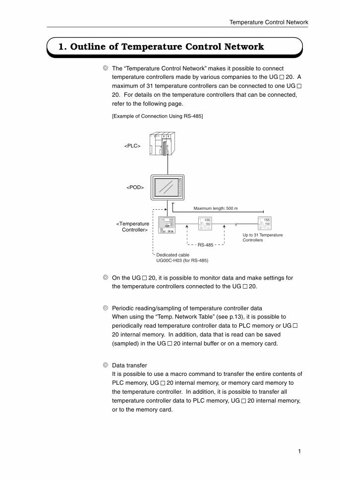
The “Temperature Control Network” makes it possible to connecttemperature controllers made by various companies to the UG 20. A
maximum of 31 temperature controllers can be connected to one UG
20. For details on the temperature controllers that can be connected,
refer to the following page.
On the UG 20, it is possible to monitor data and make settings forthe temperature controllers connected to the UG 20.
Periodic reading/sampling of temperature controller dataWhen using the “Temp. Network Table” (see p.13), it is possible to
periodically read temperature controller data to PLC memory or UG
20 internal memory. In addition, data that is read can be saved
(sampled) in the UG 20 internal buffer or on a memory card.
Data transferIt is possible to use a macro command to transfer the entire contents of
PLC memory, UG 20 internal memory, or memory card memory to
the temperature controller. In addition, it is possible to transfer all
temperature controller data to PLC memory, UG 20 internal memory,
or to the memory card.
. . .
. . .
. . .
. . .
. . .
. . .
. . .
. . .
. . .
. . .
. . .
. . .
. . .
. . .
. . .
. . .
run
s t o p
<Temperature Controller>
<POD>
<PLC>
[Example of Connection Using RS-485]
A/MSET/ENT
PV
SP
SP2 3 4
AL1 2 3 MAN
100
90
PV
SP2
AL1
SET/ENT
2OUT
155150
PV
SP2
AL1
SET/ENT
2OUT
155150
Dedicated cableUG00C-H03 (for RS-485)
RS-485
Up to 31 Temperature Controllers
Maximum length: 500 m
2
Temperature Control Network
Notes
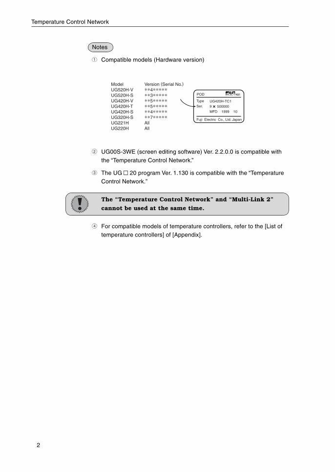
1 Compatible models (Hardware version)
Model Version (Serial No.) UG520H-V **4***** UG520H-S **3***** UG420H-V **5***** UG420H-T **5***** UG420H-S **4***** UG320H-S **7***** UG221H All UG220H All
POD
Type
Ser.
Fuji Electric Co., Ltd. Japan
UG420H-TC1
9 500000
MFD 1999 10
2 UG00S-3WE (screen editing software) Ver. 2.2.0.0 is compatible with
the “Temperature Control Network.”
3 The UG 20 program Ver. 1.130 is compatible with the “Temperature
Control Network.”
The “Temperature Control Network” and “Multi-Link 2”
cannot be used at the same time.
4 For compatible models of temperature controllers, refer to the [List of
temperature controllers] of [Appendix].
3
Temperature Control Network
2. Connection Cables
Use our UG00C-H03/UG00C-B temperature controller connection cable to
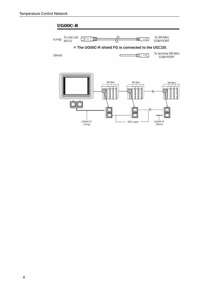
connect the UG 20 and the temperature controller. Use our UG00C-R (3
m) temperature control connection cable only when using the RKC control-
ler unit SR-Mini (for RS-422). For details on connecting the temperature
controller, refer to the instruction manual for the applicable temperature
controller.
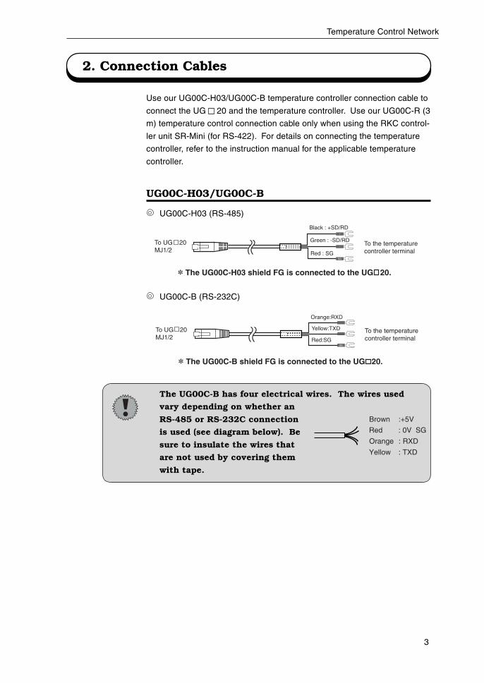
UG00C-H03/UG00C-B
UG00C-H03 (RS-485)
UG00C-B (RS-232C)
The UG00C-B has four electrical wires. The wires used
vary depending on whether an
RS-485 or RS-232C connection
is used (see diagram below). Be
sure to insulate the wires that
are not used by covering them
with tape.
SG
Orange:RXD
Yellow:TXD
Red:SG
To the temperature controller terminal
To UG 20MJ1/2
* The UG00C-B shield FG is connected to the UG 20.
-
SG
+
Black : +SD/RD
Green : -SD/RD
Red : SG
To the temperature controller terminal
To UG 20MJ1/2
* The UG00C-H03 shield FG is connected to the UG 20.
Red : 0V SG
Orange : RXD
Yellow : TXD
Brown :+5V
4
Temperature Control Network
UG00C-R
To SR-MiniCOM.PORT
To terminal SR-MiniCOM.PORT
(Long)
(Short)
To UG 20MJ1/2
* The UG00C-R shield FG is connected to the UG 20.
CO
M.P
OR
T1
CO
M.P
OR
T2
TIO TIO TIO
CO
M.P
OR
T1
CO
M.P
OR
T2
TIO TIO TIO
CO
M.P
OR
T1
CO
M.P
OR
T2
TIO TIO TIO
MJ1MJ2
UG00C-R (Long)
RKC cable
SR-MiniSR-Mini
CO
M.P
OR
T1
CO
M.P
OR
T2
CO
M.P
OR
T1
CO
M.P
OR
T2
CO
M.P
OR
T1
CO
M.P
OR
T2
UG00C-R (Short)
SR-Mini
5
Temperature Control Network
3. Setting the Termination Resistor
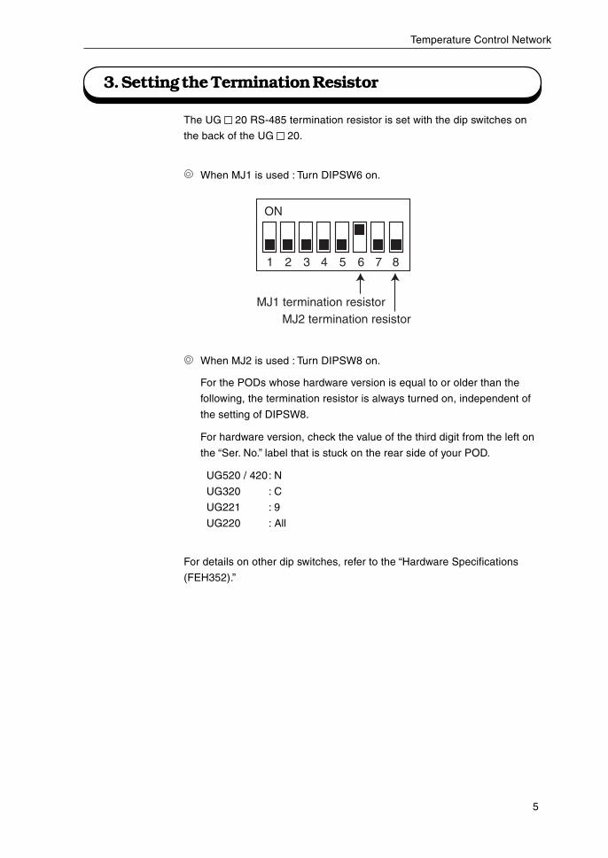
The UG 20 RS-485 termination resistor is set with the dip switches on
the back of the UG 20.
When MJ1 is used : Turn DIPSW6 on.
When MJ2 is used : Turn DIPSW8 on.
For the PODs whose hardware version is equal to or older than the
following, the termination resistor is always turned on, independent of
the setting of DIPSW8.
For hardware version, check the value of the third digit from the left on
the “Ser. No.” label that is stuck on the rear side of your POD.
UG520 / 420: N
UG320 : C
UG221 : 9
UG220 : All
For details on other dip switches, refer to the “Hardware Specifications
(FEH352).”
ON
1 2 3 4 5 6 7 8
MJ1 termination resistorMJ2 termination resistor
6
Temperature Control Network
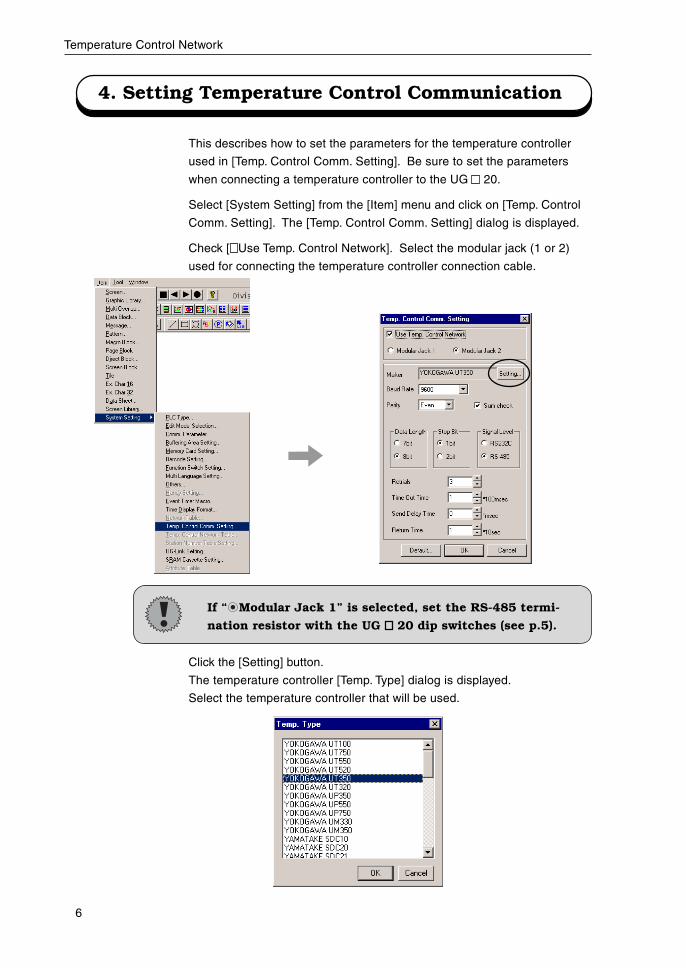
4. Setting Temperature Control Communication
This describes how to set the parameters for the temperature controller
used in [Temp. Control Comm. Setting]. Be sure to set the parameters
when connecting a temperature controller to the UG 20.
Select [System Setting] from the [Item] menu and click on [Temp. Control
Comm. Setting]. The [Temp. Control Comm. Setting] dialog is displayed.
Check [ Use Temp. Control Network]. Select the modular jack (1 or 2)
used for connecting the temperature controller connection cable.
If “ Modular Jack 1” is selected, set the RS-485 termi-
nation resistor with the UG 20 dip switches (see p.5).
Click the [Setting] button.
The temperature controller [Temp. Type] dialog is displayed.
Select the temperature controller that will be used.
7
Temperature Control Network
Baud Rate
Set the speed used for communication with the temperature controller.
4800/9600/19200/38400/57600/115000 bps
Parity
Set the parity used for communication with the temperature controller.
None/Odd/Even
Data Length
Set the data length used for communication with the temperature
controller.
7 bit/8 bit
Stop Bit
Set the stop bit used for communication with the temperature control-
ler.
1 bit/2 bits
Signal Level
Set the signal level used for communication with the temperature
controller.
RS-485/RS-232C
Be sure that the settings above correspond to the com-
munication settings on the temperature controller. In
addition, because the UG 20 is set as “Sumcheck:
Provided(fixed)”, set the temperature controller to
“Sumcheck: Provided” as well.
Retrials
Set the number of times to perform retry if a communication error
occurs.
Time-Out Time (* 100 msec)
Set the time for receiving a response signal from the temperature
controller. If a response is not received within the set time, retry is
performed.
Send Delay Time (* msec)
When data is received from the temperature controller, set the send
delay time to send a reply to the temperature controller.
8
Temperature Control Network
Return Time (* 10 sec)
If the power for a connected temperature controller is turned off,
reading of data from that temperature controller is temporarily prohib-
ited. A return check is performed as specified by the time set for return
time.
Default
When this is clicked, the settings for each temperature controller will
revert to the default settings.
9
Temperature Control Network
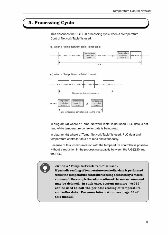
5. Processing Cycle
This describes the UG 20 processing cycle when a “Temperature
Control Network Table” is used.
In diagram (a) where a “Temp. Network Table” is not used, PLC data is not
read while temperature controller data is being read.
In diagram (b) where a “Temp. Network Table” is used, PLC data and
temperature controller data are read simultaneously.
Because of this, communication with the temperature controller is possible
without a reduction in the processing capacity between the UG 20 and
the PLC.
(a) When a "Temp. Network Table" is not used :
PLC data1 PLC data 2 PLC data 3 PLC data n
1 cycle
(b) When a "Temp. Network Table" is used :
PLC data1 PLC data 2 PLC data 3 PLC data n
One screen data reading cycle
Temperaturecontroller
data 1
One temperature controller data reading cycle
Temperaturecontroller
data 2
Temperaturecontroller
data n
Temperaturecontroller
data 1
Temperaturecontroller
data n
<When a “Temp. Network Table” is used>
If periodic reading of temperature controller data is performed
while the temperature controller is being accessed by a macro
command, the completion of execution of the macro command
may be delayed. In such case, system memory “$s762”
can be used to halt the periodic reading of temperature
controller data. For more information, see page 33 of
this manual.
10
Temperature Control Network
6. Directly Specifying Temperature Controller Memory
The following operations are possible during screen creation when placing
parts allocated in temperature controller memory:
• Monitoring the temperature controller current temperature and setting
value on the data display.
• Using the lamp/relay mode to show the upper/lower limits of the alarm
display.
• Using the entry mode to change temperature controller settings.
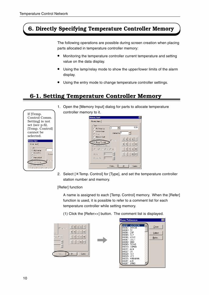
If [Temp.Control Comm.Setting] is notset (see p.6),[Temp. Control]cannot beselected.
1. Open the [Memory Input] dialog for parts to allocate temperature
controller memory to it.
6-1. Setting Temperature Controller Memory
2. Select [ Temp. Control] for [Type], and set the temperature controller
station number and memory.
[Refer] function
A name is assigned to each [Temp. Control] memory. When the [Refer]
function is used, it is possible to refer to a comment list for each
temperature controller while setting memory.
(1) Click the [Refer>>] button. The comment list is displayed.
11
Temperature Control Network
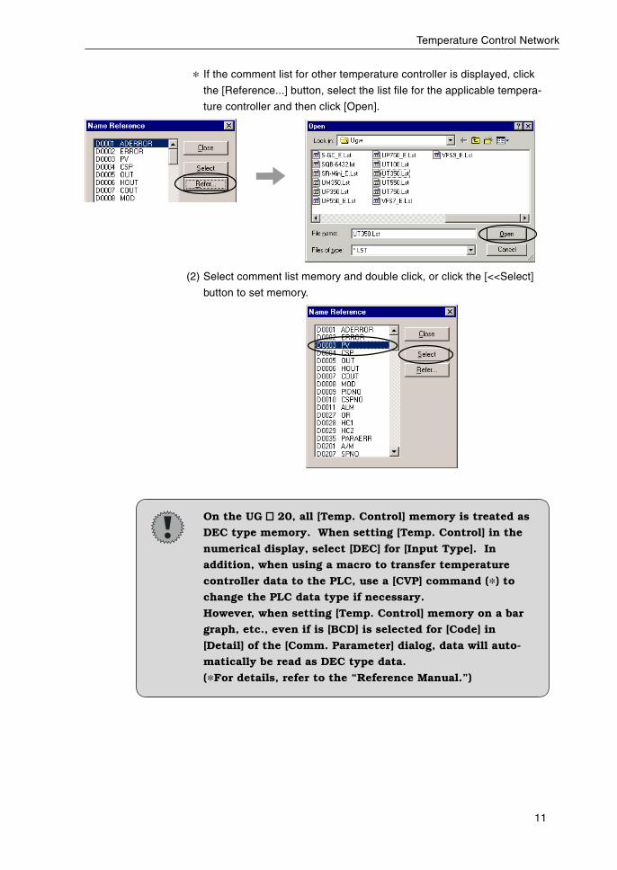
* If the comment list for other temperature controller is displayed, click
the [Reference...] button, select the list file for the applicable tempera-
ture controller and then click [Open].
(2) Select comment list memory and double click, or click the [<<Select]
button to set memory.
On the UG 20, all [Temp. Control] memory is treated as
DEC type memory. When setting [Temp. Control] in the
numerical display, select [DEC] for [Input Type]. In
addition, when using a macro to transfer temperature
controller data to the PLC, use a [CVP] command (*) to
change the PLC data type if necessary.
However, when setting [Temp. Control] memory on a bar
graph, etc., even if is [BCD] is selected for [Code] in
[Detail] of the [Comm. Parameter] dialog, data will auto-
matically be read as DEC type data.
(*For details, refer to the “Reference Manual.”)
12
Temperature Control Network
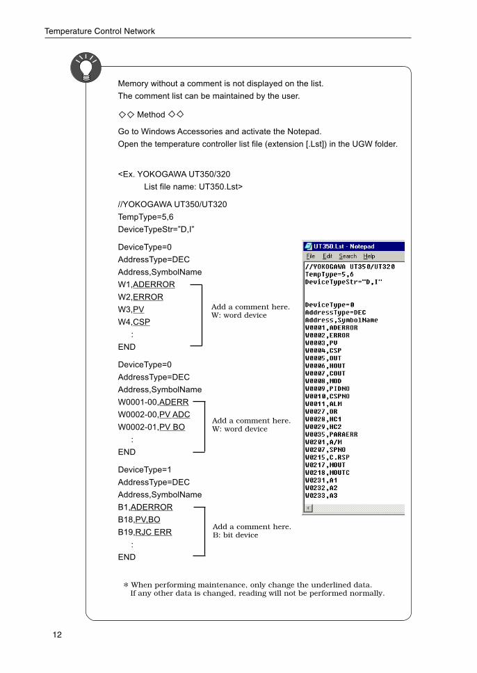
Memory without a comment is not displayed on the list.
The comment list can be maintained by the user.
Method
Go to Windows Accessories and activate the Notepad.
Open the temperature controller list file (extension [.Lst]) in the UGW folder.
<Ex. YOKOGAWA UT350/320
List file name: UT350.Lst>
//YOKOGAWA UT350/UT320
TempType=5,6
DeviceTypeStr=”D,I”
DeviceType=0
AddressType=DEC
Address,SymbolName
W1,ADERROR
W2,ERROR
W3,PV
W4,CSP
:
END
DeviceType=0
AddressType=DEC
Address,SymbolName
W0001-00,ADERR
W0002-00,PV ADC
W0002-01,PV BO
:
END
DeviceType=1
AddressType=DEC
Address,SymbolName
B1,ADERROR
B18,PV,BO
B19,RJC ERR
:
END
* When performing maintenance, only change the underlined data. If any other data is changed, reading will not be performed normally.
Add a comment here.B: bit device
Add a comment here.W: word device
Add a comment here.W: word device
13
Temperature Control Network
7. Using a “Temp. Network Table”
When a “Temp. Network Table” is used, the following operations are
possible:
Periodic Reading of Temperature Control Data … P17
Temperature Control Data Sampling …………… P18
Temperature Control Data Transfer ……………… P20
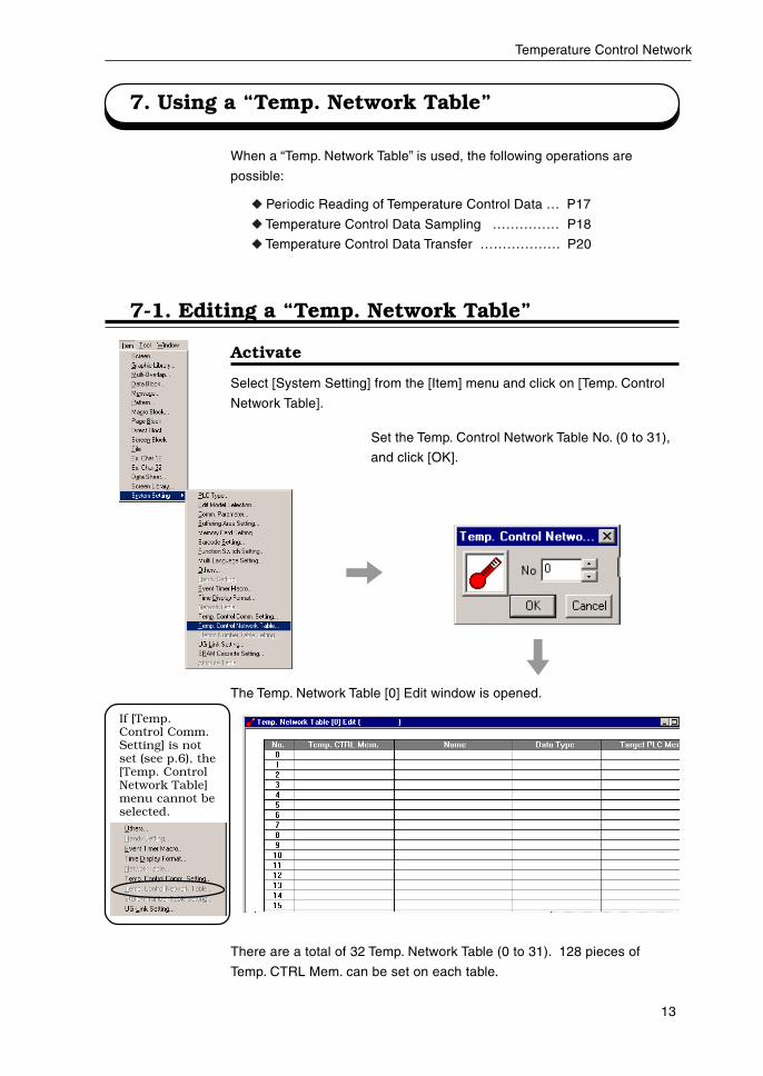
If [Temp.Control Comm.Setting] is notset (see p.6), the[Temp. ControlNetwork Table]menu cannot beselected.
7-1. Editing a “Temp. Network Table”
Activate
Select [System Setting] from the [Item] menu and click on [Temp. Control
Network Table].
Set the Temp. Control Network Table No. (0 to 31),
and click [OK].
The Temp. Network Table [0] Edit window is opened.
There are a total of 32 Temp. Network Table (0 to 31). 128 pieces of
Temp. CTRL Mem. can be set on each table.
14
Temperature Control Network
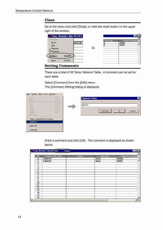
Close
Go to the menu and click [Close], or click the close button on the upper
right of the window.
Or
Setting Comments
There are a total of 32 Temp. Network Table. A comment can be set for
each table.
Select [Comment] from the [Edit] menu.
The [Comment Setting] dialog is displayed.
Enter a comment and click [OK]. The comment is displayed as shown
below.
15
Temperature Control Network
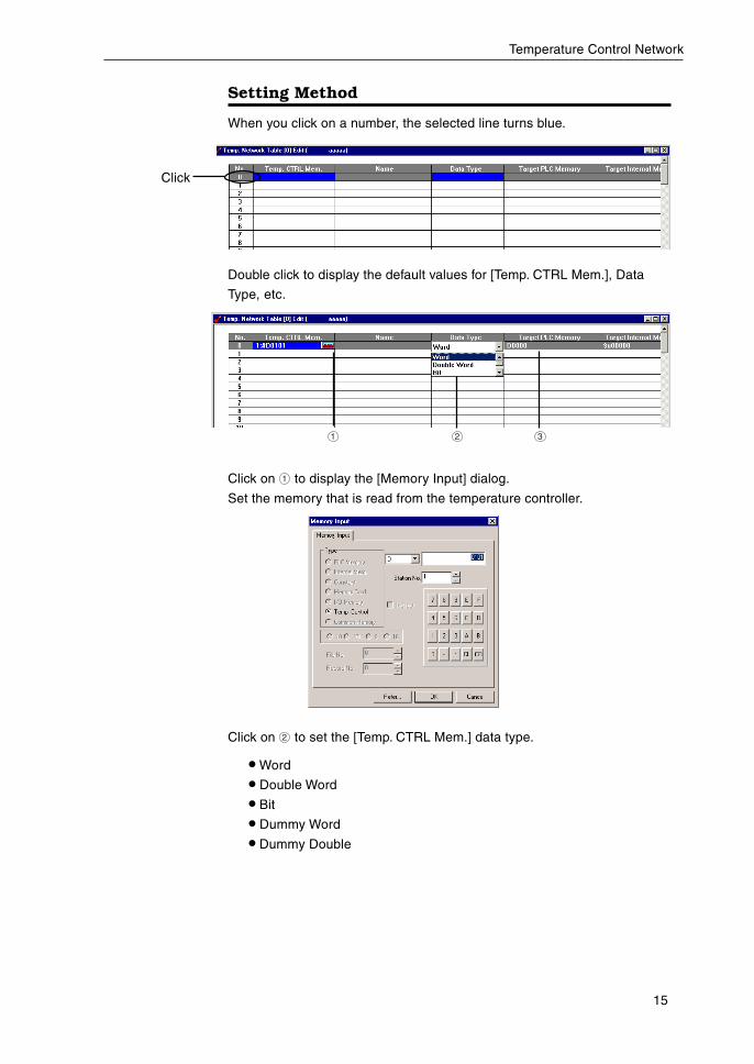
Setting Method
When you click on a number, the selected line turns blue.
Double click to display the default values for [Temp. CTRL Mem.], Data
Type, etc.
Click on 1 to display the [Memory Input] dialog.
Set the memory that is read from the temperature controller.
Click on 2 to set the [Temp. CTRL Mem.] data type.
• Word
• Double Word
• Bit
• Dummy Word
• Dummy Double
Click
1 2 3
16
Temperature Control Network
Word The data in a temperature controller is treated as one-word
numerical data. The data type of a temperature controller is
automatically converted to DEC type, and it is transferred to
the store target PLC (internal) memory.
Double Word The data in a temperature controller is treated as double-word
numerical data. The data type of a temperature controller is
automatically converted to DEC type, and it is transferred to
the store target PLC (internal) memory.
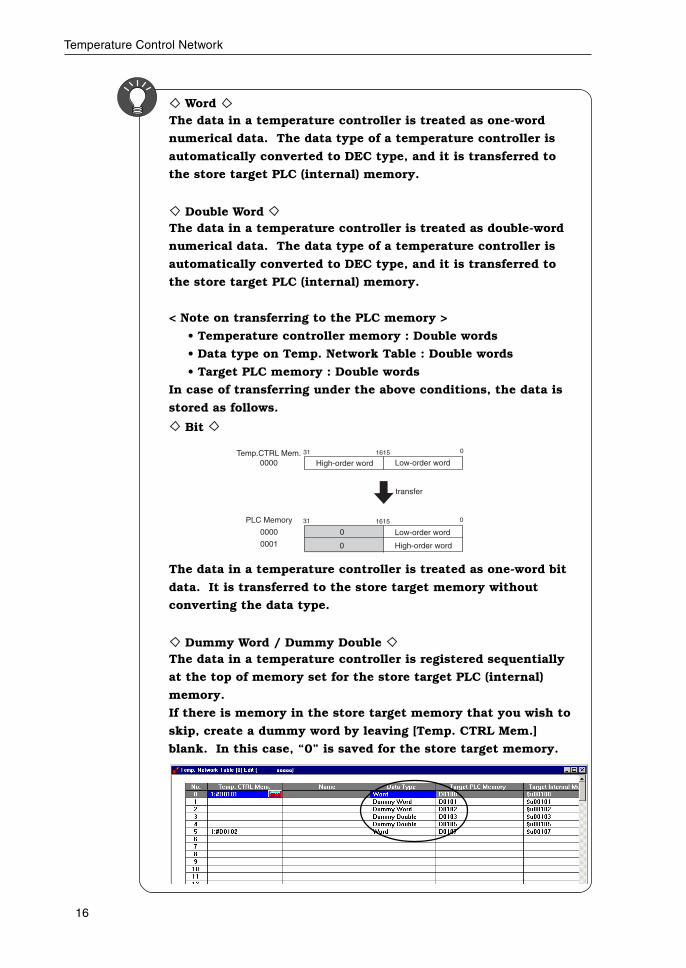
< Note on transferring to the PLC memory >
• Temperature controller memory : Double words
• Data type on Temp. Network Table : Double words
• Target PLC memory : Double words
In case of transferring under the above conditions, the data is
stored as follows.
Bit
The data in a temperature controller is treated as one-word bit
data. It is transferred to the store target memory without
converting the data type.
Dummy Word / Dummy Double The data in a temperature controller is registered sequentially
at the top of memory set for the store target PLC (internal)
memory.
If there is memory in the store target memory that you wish to
skip, create a dummy word by leaving [Temp. CTRL Mem.]
blank. In this case, “0” is saved for the store target memory.
Temp.CTRL Mem.0000 High-order word Low-order word
0161531
PLC Memory
0000
0001
0 Low-order word
0161531
High-order word0
transfer
17
Temperature Control Network
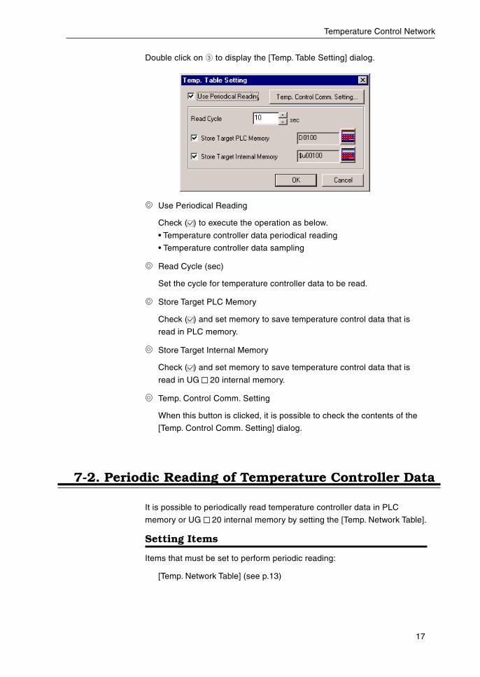
Double click on 3 to display the [Temp. Table Setting] dialog.
Use Periodical Reading
Check ( ) to execute the operation as below.
• Temperature controller data periodical reading
• Temperature controller data sampling
Read Cycle (sec)
Set the cycle for temperature controller data to be read.
Store Target PLC Memory
Check ( ) and set memory to save temperature control data that is
read in PLC memory.
Store Target Internal Memory
Check ( ) and set memory to save temperature control data that is
read in UG 20 internal memory.
Temp. Control Comm. Setting
When this button is clicked, it is possible to check the contents of the
[Temp. Control Comm. Setting] dialog.
7-2. Periodic Reading of Temperature Controller Data
It is possible to periodically read temperature controller data in PLC
memory or UG 20 internal memory by setting the [Temp. Network Table].
Setting Items
Items that must be set to perform periodic reading:
[Temp. Network Table] (see p.13)
18
Temperature Control Network
7-3. Sampling of Temperature Controller Data
It is possible to sample temperature controller data by linking the [Temp.
Network Table] and buffering area.
Setting Items
Items that must be set to perform sampling:
• Temp. Network Table (see p.13)
• Buffering area settings
• Memory card settings (when the memory card is set as the store target
in buffering area settings)
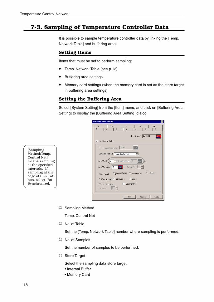
Setting the Buffering Area
Select [System Setting] from the [Item] menu, and click on [Buffering Area
Setting] to display the [Buffering Area Setting] dialog.
Sampling Method
Temp. Control Net
No. of Table
Set the [Temp. Network Table] number where sampling is performed.
No. of Samples
Set the number of samples to be performed.
Store Target
Select the sampling data store target.
• Internal Buffer
• Memory Card
[SamplingMethod:Temp.Control Net]means samplingat the specifiedintervals. Ifsampling at theedge of 0 ->1 ofbits, select [BitSynchronize].
19
Temperature Control Network
Full Processing
Select the processing when the store target becomes full.
• Continuous: When the [No. of Samples] is exceeded, data is
deleted, beginning with the oldest data.
• Stop: When the [No. of Samples] is exceeded, stop sampling.
Use Start Bit
This bit enables the user to control the start, stop and restart of
sampling. For more information, refer to the “UG 20 Series Manual
<Reference>” (FEH351).
Calculating Buffering Area Capacity
The maximum capacity is 32K words.
If [Temp. Control Net] is set for the [Sampling Method], the calculation
method is as shown below.
1 sample = [No. of Words]* + 2 words
Buffer size = [No. of Samples] 1 sample
* [No. of Words] are the number of the words used for memory in the
[Temp. Network Table] set in [No.of Table].
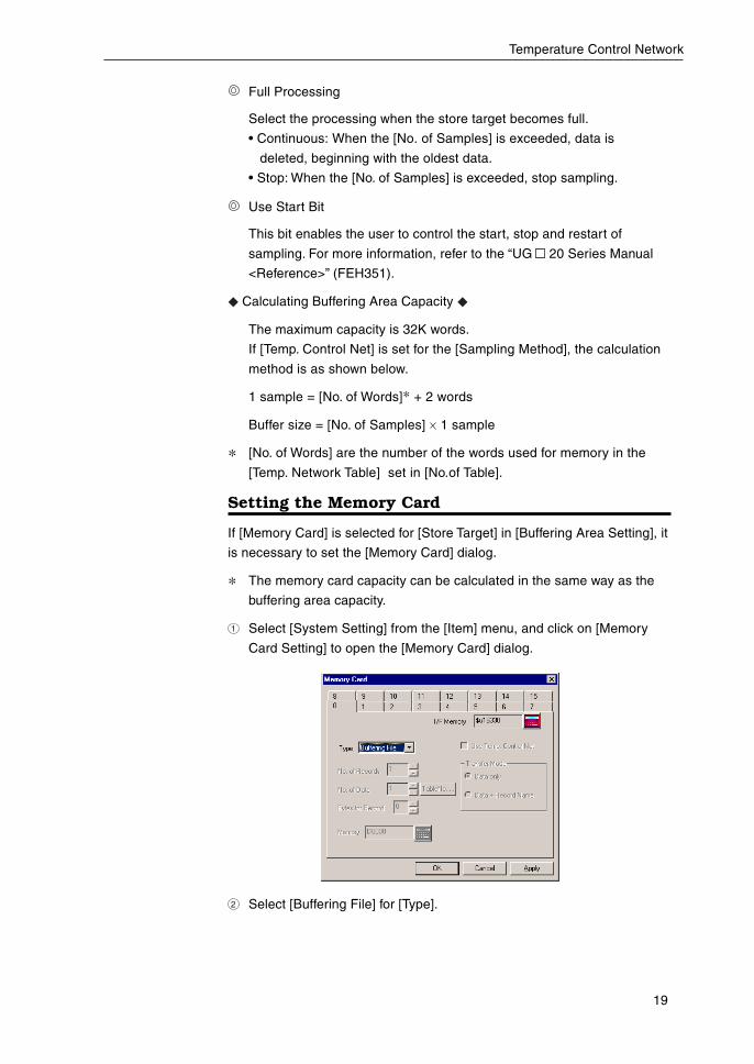
Setting the Memory Card
If [Memory Card] is selected for [Store Target] in [Buffering Area Setting], it
is necessary to set the [Memory Card] dialog.
* The memory card capacity can be calculated in the same way as the
buffering area capacity.
1 Select [System Setting] from the [Item] menu, and click on [Memory
Card Setting] to open the [Memory Card] dialog.
2 Select [Buffering File] for [Type].
20
Temperature Control Network
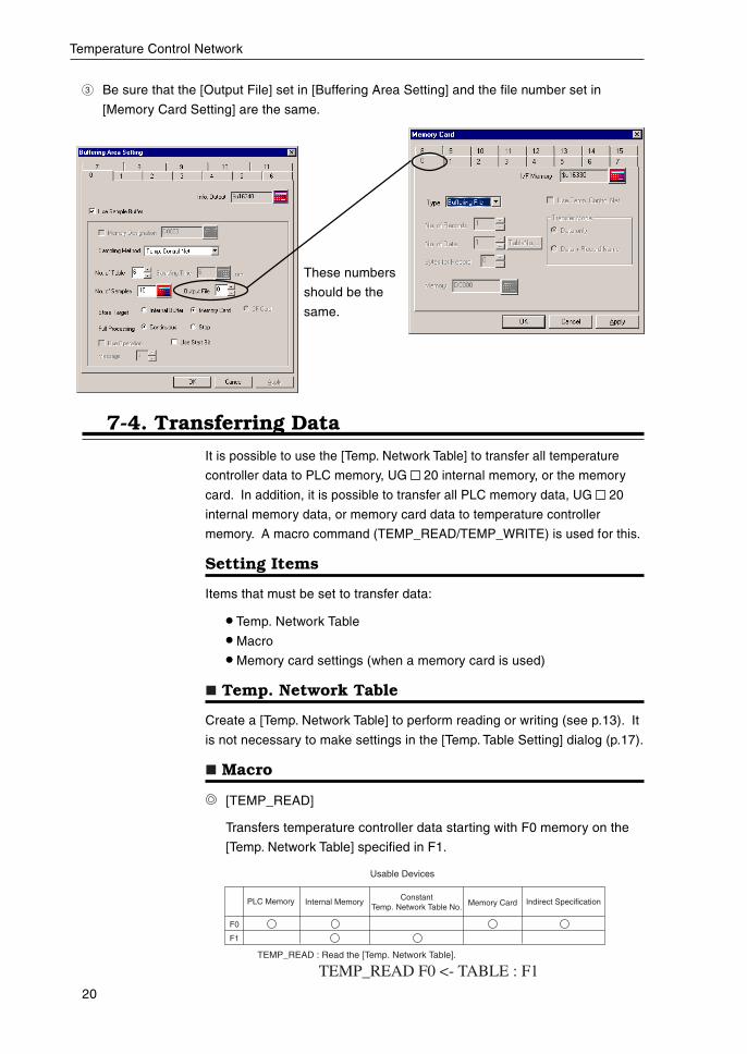
These numbers
should be the
same.
7-4. Transferring Data
It is possible to use the [Temp. Network Table] to transfer all temperature
controller data to PLC memory, UG 20 internal memory, or the memory
card. In addition, it is possible to transfer all PLC memory data, UG 20
internal memory data, or memory card data to temperature controller
memory. A macro command (TEMP_READ/TEMP_WRITE) is used for this.
Setting Items
Items that must be set to transfer data:
• Temp. Network Table
• Macro
• Memory card settings (when a memory card is used)
Temp. Network Table
Create a [Temp. Network Table] to perform reading or writing (see p.13). It
is not necessary to make settings in the [Temp. Table Setting] dialog (p.17).
Macro
[TEMP_READ]
Transfers temperature controller data starting with F0 memory on the
[Temp. Network Table] specified in F1.
Indirect Specification
F0
F1
Usable Devices
TEMP_READ F0 <- TABLE : F1TEMP_READ : Read the [Temp. Network Table].
PLC Memory Internal Memory Constant Temp. Network Table No. Memory Card
3 Be sure that the [Output File] set in [Buffering Area Setting] and the file number set in
[Memory Card Setting] are the same.
21
Temperature Control Network
[TEMP_WRITE]
Transfers the data starting with F1 memory to the [Temp. Network
Table] memory specified in F0.
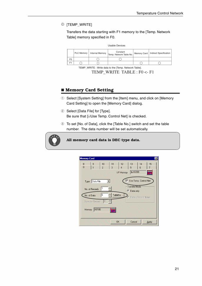
Memory Card Setting
1 Select [System Setting] from the [Item] menu, and click on [Memory
Card Setting] to open the [Memory Card] dialog.
2 Select [Data File] for [Type].
Be sure that [ Use Temp. Control Net] is checked.
3 To set [No. of Data], click the [Table No.] switch and set the table
number. The data number will be set automatically.
All memory card data is DEC type data.
TEMP_WRITE TABLE : F0 <- F1TEMP_WRITE : Write data to the [Temp. Network Table].
Indirect Specification
Usable Devices
PLC Memory Internal Memory Constant Temp. Network Table No. Memory Card
F0
F1
22
Temperature Control Network
8. Indirect Designation Memory
It is possible to access [Temp. Control] memory to use indirect designation
memory in macro commands.
This section explains the way to use indirect designation memory for
[Temp. Control] memory. About the way to use it for PLC or internal
memory, refer to “Reference Manual.”
The internal designation memory ($u) should be used for indirect designa-
tion memory.
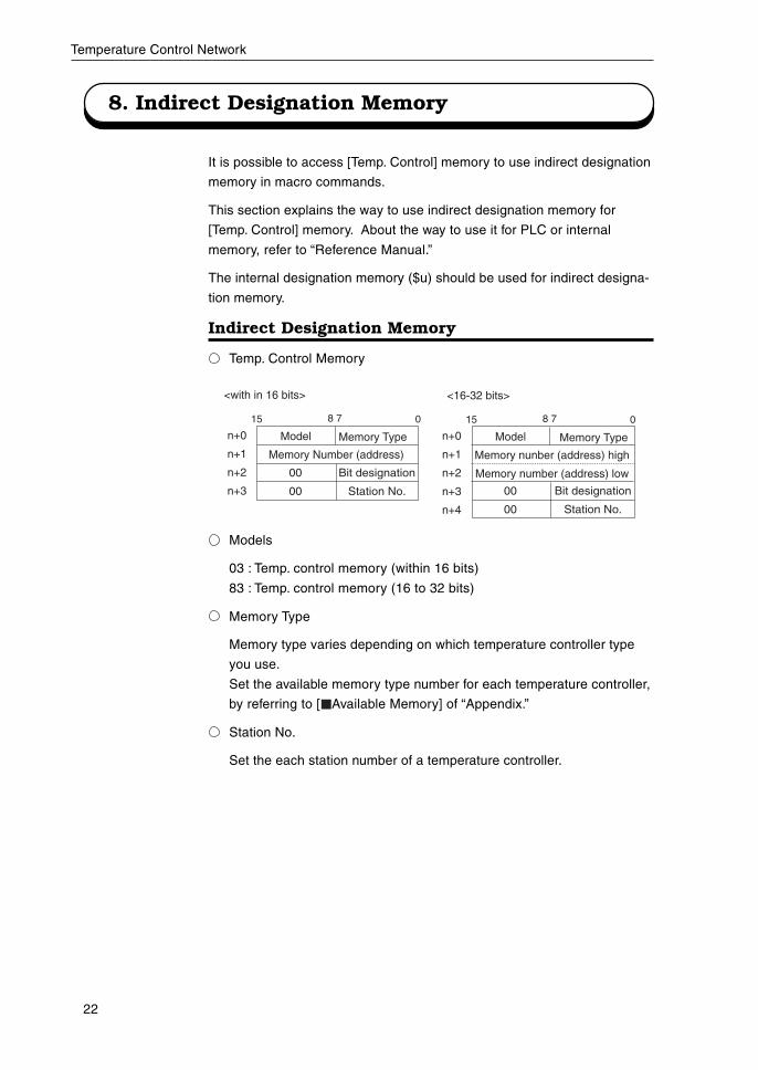
Indirect Designation Memory
Temp. Control Memory
Models
03 : Temp. control memory (within 16 bits)
83 : Temp. control memory (16 to 32 bits)
Memory Type
Memory type varies depending on which temperature controller type
you use.
Set the available memory type number for each temperature controller,
by referring to [ Available Memory] of “Appendix.”
Station No.
Set the each station number of a temperature controller.
Model Memory Type
Memory Number (address)
Bit designation
Station No.
n+0
n+1
n+2
n+3
15 8 7 0
Model Memory Type
Memory nunber (address) high
Memory number (address) low
Bit designation
Station No.
n+0
n+1
n+2
n+3
n+4
15 8 7 0
<with in 16 bits> <16-32 bits>
00
00 00
00
23
Temperature Control Network
9. Control of Temperature Controller
It is possible to control a temperature controller by using a macro com-
mand, [Temp_CTL].
The available actions to control are different according to the used tem-
perature controller.
For more information about the contents of control, refer to the
[ TEMP_CTL] command of each temperature controller on “Appendix.”
Macro
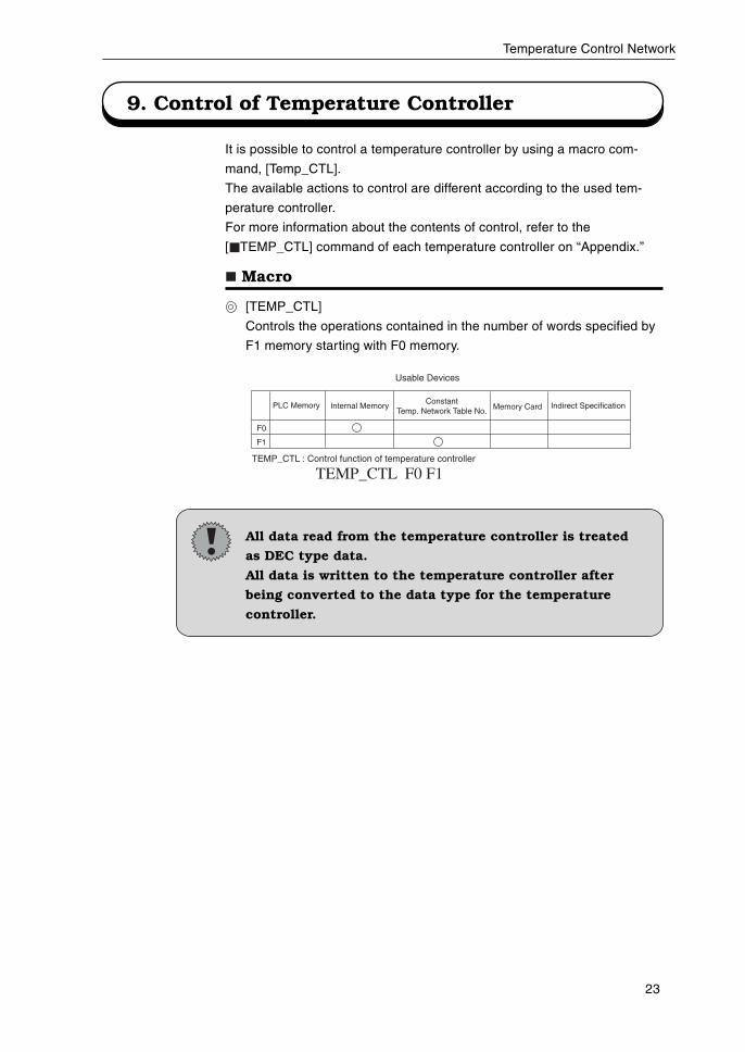
[TEMP_CTL]
Controls the operations contained in the number of words specified by
F1 memory starting with F0 memory.
All data read from the temperature controller is treated
as DEC type data.
All data is written to the temperature controller after
being converted to the data type for the temperature
controller.
F0
F1
TEMP_CTL : Control function of temperature controller
Indirect Specification
Usable Devices
PLC Memory Internal Memory Constant Temp. Network Table No. Memory Card
TEMP_CTL F0 F1
24
Temperature Control Network
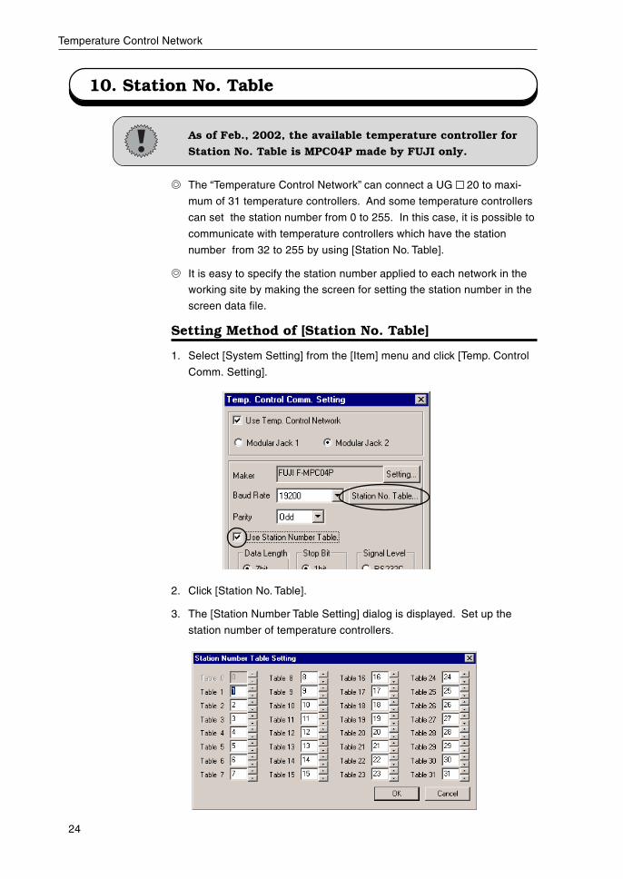
10. Station No. Table
As of Feb., 2002, the available temperature controller for
Station No. Table is MPC04P made by FUJI only.
The “Temperature Control Network” can connect a UG 20 to maxi-
mum of 31 temperature controllers. And some temperature controllers
can set the station number from 0 to 255. In this case, it is possible to
communicate with temperature controllers which have the station
number from 32 to 255 by using [Station No. Table].
It is easy to specify the station number applied to each network in the
working site by making the screen for setting the station number in the
screen data file.
Setting Method of [Station No. Table]
1. Select [System Setting] from the [Item] menu and click [Temp. Control
Comm. Setting].
2. Click [Station No. Table].
3. The [Station Number Table Setting] dialog is displayed. Set up the
station number of temperature controllers.
25
Temperature Control Network
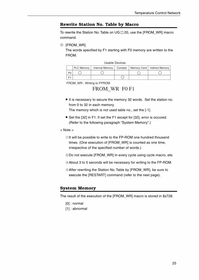
Rewrite Station No. Table by Macro
To rewrite the Station No. Table on UG 20, use the [FROM_WR] macro
command.
[FROM_WR]
The words specified by F1 starting with F0 memory are written to the
FROM.
• It is necessary to secure the memory 32 words. Set the station no.
from 0 to 32 in each memory.
The memory which is not used table no., set the [-1].
• Set the [32] in F1. If set the F1 except for [32], error is occured.
(Refer to the following paragraph “System Memory”.)
< Note >
1 It will be possible to write to the FP-ROM one hundred thousand
times. (One execution of [FROM_WR] is counted as one time,
irrespective of the specified number of words.)
2 Do not execute [FROM_WR] in every cycle using cycle macro, ete.
3 About 3 to 5 seconds will be necessary for writing to the FP-ROM.
4 After rewriting the Station No. Table by [FROM_WR], be sure to
execute the [RESTART] command (refer to the next page).
System Memory
The result of the execution of the [FROM_WR] macro is stored in $s728.
[0] : normal
[1] : abnormal
PLC Memory Internal Memory Constan Memory Card Indirect Memory
F0
F1
Usable Devices
FROM_WR F0 F1FROM_WR : Writing to FPROM
26
Temperature Control Network
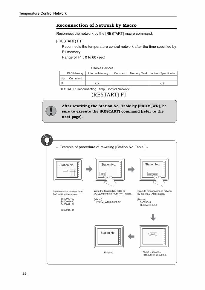
Reconnection of Network by Macro
Reconnect the network by the [RESTART] macro command.
[(RESTART) F1]
Reconnects the temperature control network after the time specified by
F1 memory.
Range of F1 : 0 to 60 (sec)
After rewriting the Station No. Table by [FROM_WR], be
sure to execute the [RESTART] command (refer to the
next page).
PLC Memory Internal Memory Constant Memory Card Indirect Specification
F0
F1
Usable Devices
(RESTART) F1RESTART : Reconnecting Temp. Control Network
Command
$u00000=00$u00001=50$u00002=51
:$u00031=81
Set the station number from $u0 to 31 at the screen.
Execute reconnection of networkby the [RESTART] macro.
[Macro]$u0050=5RESTART $u50
Write the Station No. Table to UG 20 by the [FROM_WR] macro.
[Macro]FROM_WR $u0000 32
WR
Station No. Station No. Station No.
reconnection
check
Finished
Station No.
About 5 seconds(because of $u0050=5)
< Example of procedure of rewriting [Station No. Table] >
27
Temperature Control Network
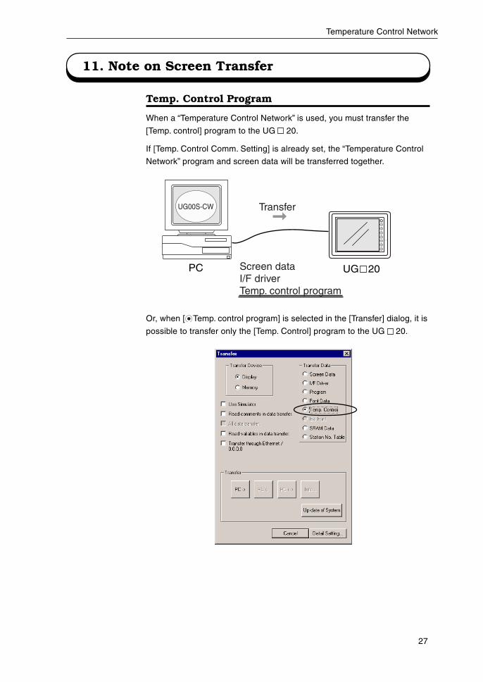
11. Note on Screen Transfer
Temp. Control Program
When a “Temperature Control Network” is used, you must transfer the
[Temp. control] program to the UG 20.
If [Temp. Control Comm. Setting] is already set, the “Temperature Control
Network” program and screen data will be transferred together.
Or, when [ Temp. control program] is selected in the [Transfer] dialog, it is
possible to transfer only the [Temp. Control] program to the UG 20.
UG00S-CW
PC Screen dataI/F driverTemp. control program
Transfer
UG 20
28
Temperature Control Network
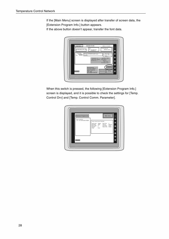
If the [Main Menu] screen is displayed after transfer of screen data, the
[Extension Program Info.] button appears.
If the above button doesn’t appear, transfer the font data.
When this switch is pressed, the following [Extension Program Info.]
screen is displayed, and it is possible to check the settings for [Temp.
Control Drv] and [Temp. Control Comm. Parameter].
Editor:MJ1
Main menuExtension Program Info.
Temp. Control Drv Ver. 1.100 YOKOGAWA GREEN
Temp. Control Comm. Parameter
Signal Lebel : RS485Baud Rate : 9600Data Length : 8Stop Bit : 1Parity : Even
Retry Time : 3Time-out :100msecSend Delay : 0msecReturn Time :10msec
1998-5 -5 07:23:30
SYSTEM PROG. VER. 1.200
FONT
VER.1.100/1.050/1.000
JAPANESE 32
I/F DRV VER.0.500
MELSEC AnA/N/U
PLC Type : MITUBISHI AnA/N/U seriesComment :
Error : stopTime-out : 0.50 sec
Retry : 3
Editor:MJ1
Ethernet VER.1.000Trans. Speed : 10BASE-TStat. No. : 192.168.1.50PORT : 10000MAC : 00000001 ERR : XXX
ExtensionProgram Info.
Main Menu
Screen DataInformation
Size : 2883584
Connection : 1:1Signal Lebel : RS232C
PLC Stat. No. : 0
Baud Rate : 19200Data Length : 7
Stop Bit : 1Parity : Even
Send Delay : 0msec
Memory-Card I/O Test
UG420H-TC1M1
29
Temperature Control Network
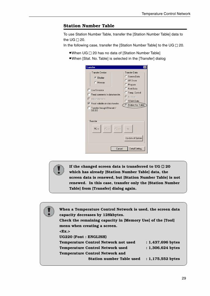
Station Number Table
To use Station Number Table, transfer the [Station Number Table] data to
the UG 20.
In the following case, transfer the [Station Number Table] to the UG 20.
•When UG 20 has no data of [Station Number Table]
•When [Stat. No. Table] is selected in the [Transfer] dialog
If the changed screen data is transferred to UG 20
which has already [Station Number Table] data, the
screen data is renewed, but [Station Number Table] is not
renewed. In this case, transfer only the [Station Number
Table] from [Transfer] dialog again.
When a Temperature Control Network is used, the screen data
capacity decreases by 128kbytes.
Check the remaining capacity in [Memory Use] of the [Tool]
menu when creating a screen.
<Ex.>
UG220 (Font : ENGLISH)
Temperature Control Network not used : 1,437,696 bytes
Temperature Control Network used : 1,306,624 bytes
Temperature Control Network and
Station number Table used : 1,175,552 bytes
30
Temperature Control Network
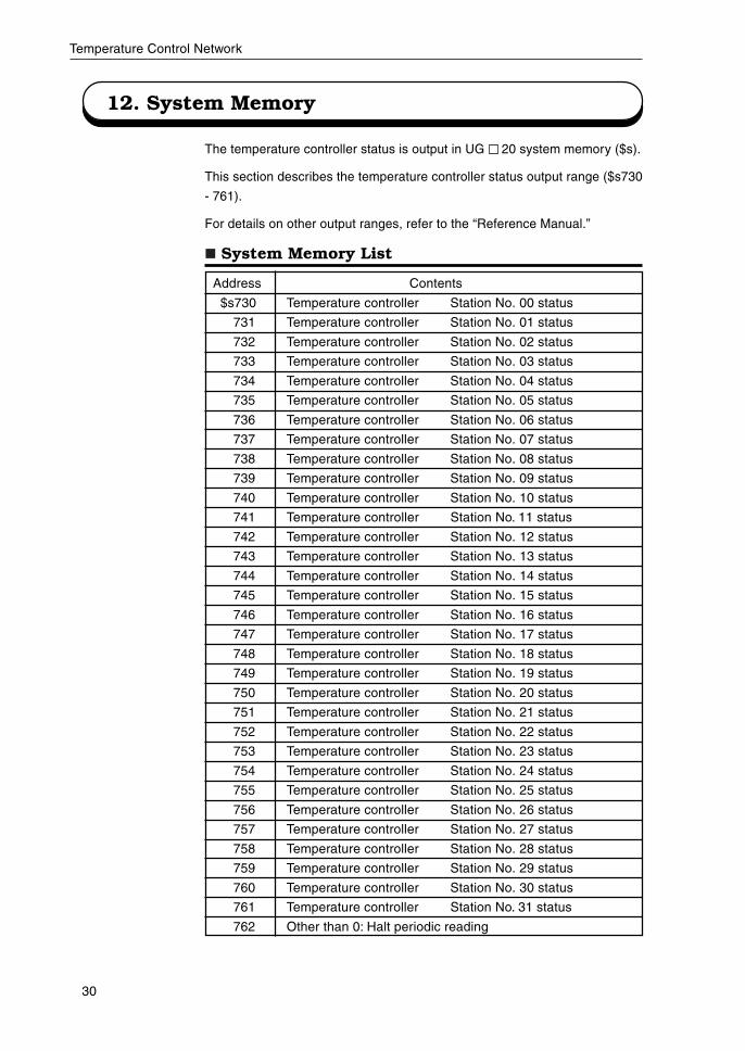
12. System Memory
The temperature controller status is output in UG 20 system memory ($s).
This section describes the temperature controller status output range ($s730
- 761).
For details on other output ranges, refer to the “Reference Manual.”
System Memory List
Address Contents
$s730 Temperature controller Station No. 00 status
731 Temperature controller Station No. 01 status
732 Temperature controller Station No. 02 status
733 Temperature controller Station No. 03 status
734 Temperature controller Station No. 04 status
735 Temperature controller Station No. 05 status
736 Temperature controller Station No. 06 status
737 Temperature controller Station No. 07 status
738 Temperature controller Station No. 08 status
739 Temperature controller Station No. 09 status
740 Temperature controller Station No. 10 status
741 Temperature controller Station No. 11 status
742 Temperature controller Station No. 12 status
743 Temperature controller Station No. 13 status
744 Temperature controller Station No. 14 status
745 Temperature controller Station No. 15 status
746 Temperature controller Station No. 16 status
747 Temperature controller Station No. 17 status
748 Temperature controller Station No. 18 status
749 Temperature controller Station No. 19 status
750 Temperature controller Station No. 20 status
751 Temperature controller Station No. 21 status
752 Temperature controller Station No. 22 status
753 Temperature controller Station No. 23 status
754 Temperature controller Station No. 24 status
755 Temperature controller Station No. 25 status
756 Temperature controller Station No. 26 status
757 Temperature controller Station No. 27 status
758 Temperature controller Station No. 28 status
759 Temperature controller Station No. 29 status
760 Temperature controller Station No. 30 status
761 Temperature controller Station No. 31 status
762 Other than 0: Halt periodic reading
31
Temperature Control Network
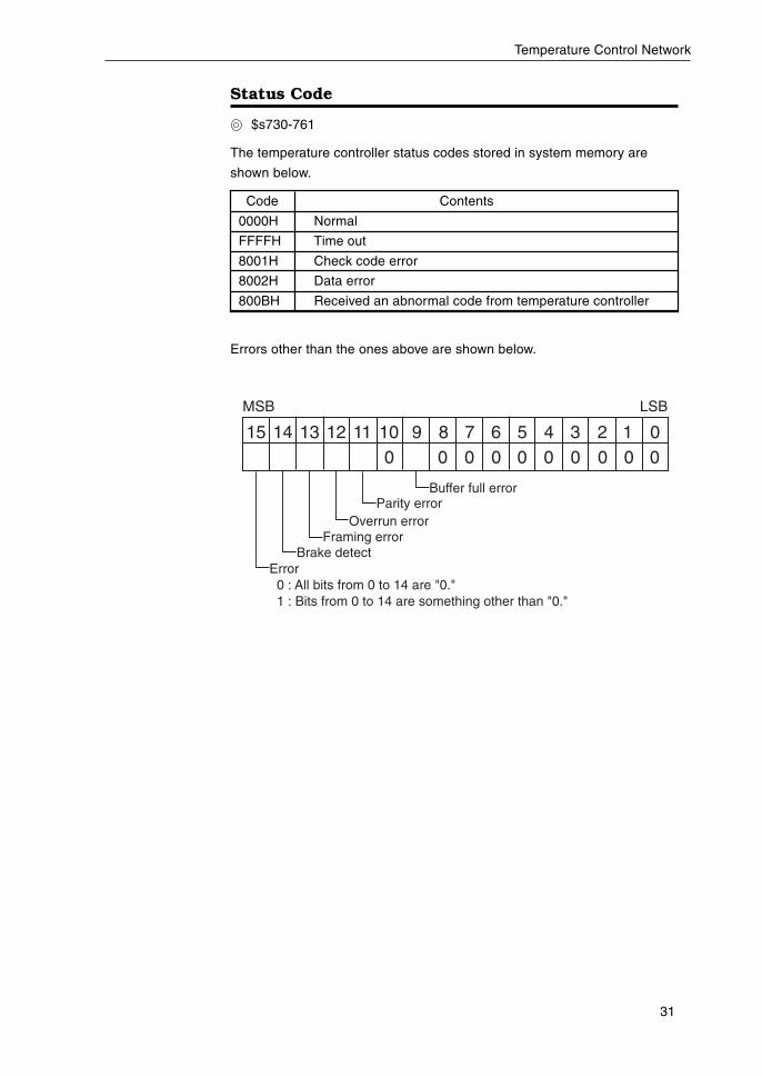
Status Code
$s730-761
The temperature controller status codes stored in system memory are
shown below.
Code Contents
0000H Normal
FFFFH Time out
8001H Check code error
8002H Data error
800BH Received an abnormal code from temperature controller
Errors other than the ones above are shown below.
15 14 13 12 11 10 9 8 7 6 5 4 3 2 1 00 0 0 0 0 0 0 0 0 0
MSB LSB
Brake detectFraming error
Overrun errorParity error
Buffer full error
Error 0 : All bits from 0 to 14 are "0." 1 : Bits from 0 to 14 are something other than "0."
32
Temperature Control Network
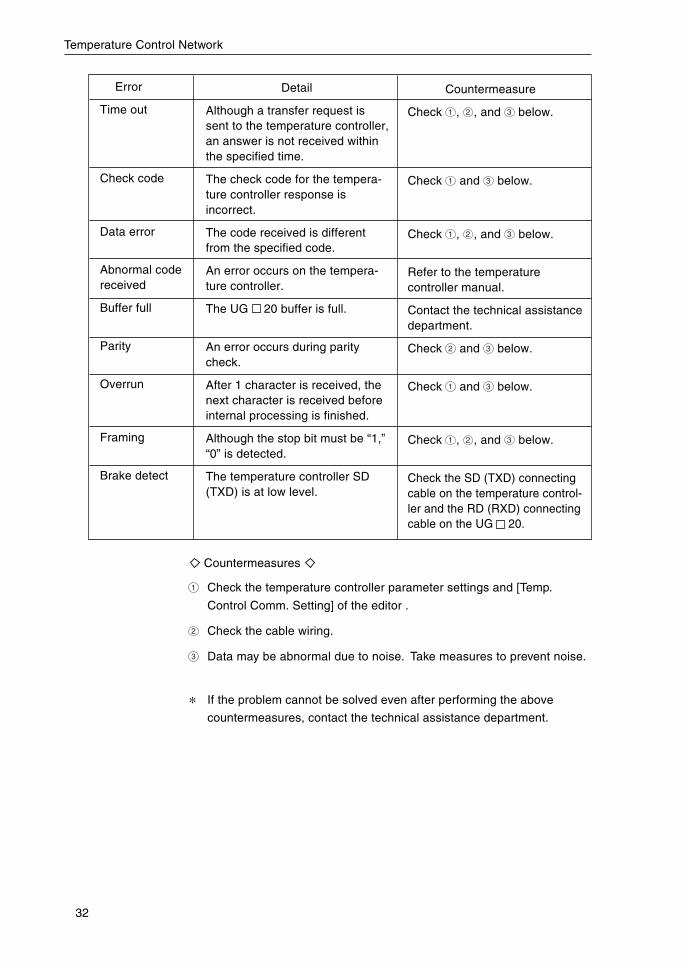
Countermeasures
1 Check the temperature controller parameter settings and [Temp.
Control Comm. Setting] of the editor .
2 Check the cable wiring.
3 Data may be abnormal due to noise. Take measures to prevent noise.
* If the problem cannot be solved even after performing the above
countermeasures, contact the technical assistance department.
Error
Time out
Check code
Data error
Abnormal codereceived
Buffer full
Parity
Overrun
Framing
Brake detect
Detail
Although a transfer request issent to the temperature controller,an answer is not received withinthe specified time.
The check code for the tempera-ture controller response isincorrect.
The code received is differentfrom the specified code.
An error occurs on the tempera-ture controller.
The UG 20 buffer is full.
An error occurs during paritycheck.
After 1 character is received, thenext character is received beforeinternal processing is finished.
Although the stop bit must be “1,”“0” is detected.
The temperature controller SD(TXD) is at low level.
Countermeasure
Check 1 , 2 , and 3 below.
Check 1 and 3 below.
Check 1 , 2 , and 3 below.
Refer to the temperaturecontroller manual.
Contact the technical assistancedepartment.
Check 2 and 3 below.
Check 1 and 3 below.
Check 1 , 2 , and 3 below.
Check the SD (TXD) connectingcable on the temperature control-ler and the RD (RXD) connectingcable on the UG 20.
33
Temperature Control Network
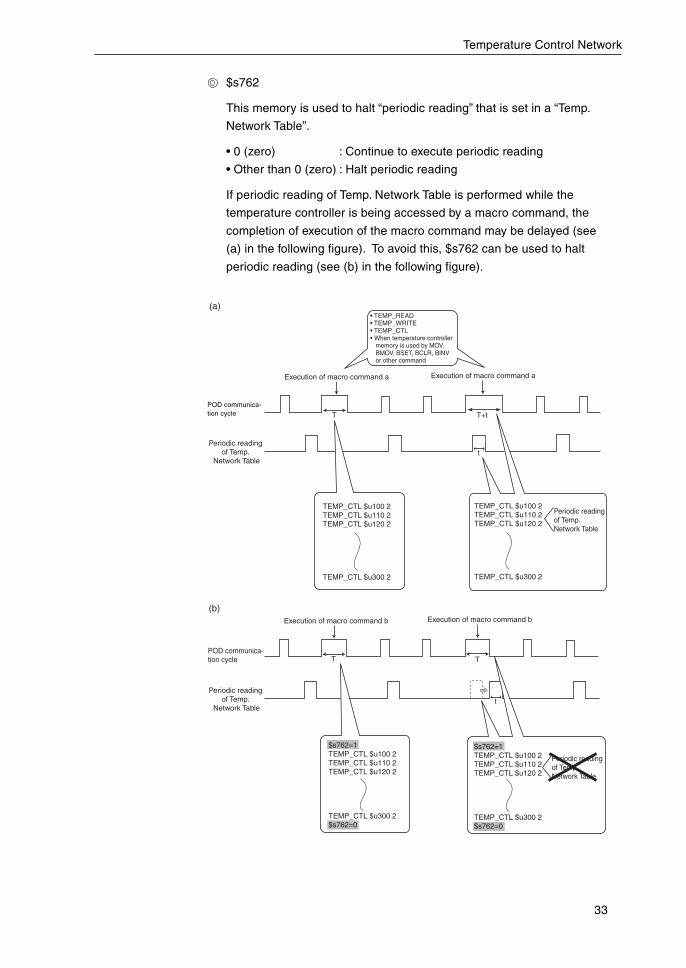
$s762
This memory is used to halt “periodic reading” that is set in a “Temp.
Network Table”.
• 0 (zero) : Continue to execute periodic reading
• Other than 0 (zero) : Halt periodic reading
If periodic reading of Temp. Network Table is performed while the
temperature controller is being accessed by a macro command, the
completion of execution of the macro command may be delayed (see
(a) in the following figure). To avoid this, $s762 can be used to halt
periodic reading (see (b) in the following figure).
Execution of macro command a Execution of macro command a
TEMP_CTL $u100 2TEMP_CTL $u110 2TEMP_CTL $u120 2
TEMP_CTL $u300 2
T
t
TEMP_CTL $u100 2TEMP_CTL $u110 2TEMP_CTL $u120 2
TEMP_CTL $u300 2
Periodic reading of Temp. Network Table
T+t
Execution of macro command b Execution of macro command b
T T
Periodic reading of Temp. Network Table
$s762=1TEMP_CTL $u100 2TEMP_CTL $u110 2TEMP_CTL $u120 2
TEMP_CTL $u300 2$s762=0
$s762=1TEMP_CTL $u100 2TEMP_CTL $u110 2TEMP_CTL $u120 2
TEMP_CTL $u300 2$s762=0
Periodic reading of Temp.
Network Table
Periodic reading of Temp.
Network Table
V6 communica-tion cycle
POD communica-tion cycle
t
• TEMP_READ• TEMP_WRITE• TEMP_CTL• When temperature controller memory is used by MOV, BMOV, BSET, BCLR, BINV or other command
(a)
(b)
POD communica-tion cycle
34
Temperature Control Network
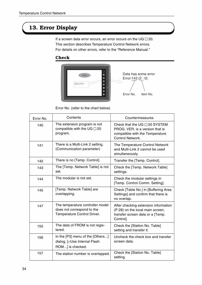
13. Error Display
If a screen data error occurs, an error occurs on the UG 20.
This section describes Temperature Control Network errors.
For details on other errors, refer to the “Reference Manual.”
Check
Error No. (refer to the chart below)
Data has some error.Error:141 (17 : 0)
Check Data has some errorError:143 (2 : 0)
Error No. Item No.
Countermeasures
Check that the UG 20 SYSTEMPROG. VER. is a version that iscompatible with the TemperatureControl Network.
The Temperature Control Networkand Multi-Link 2 cannot be usedsimultaneously.
Transfer the [Temp. Control].
Check the [Temp. Network Table]settings.
Check the modular settings in[Temp. Control Comm. Setting].
Check [Table No.] in [Buffering AreaSettings] and confirm that there isno overlap.
After checking extension information(P.28) on the local main screen,transfer screen data or a [Temp.Control].
Check the [Station No. Table]setting and transfer it.
Uncheck the check box and transferscreen data.
Check the [Station No. Table]setting.
Error No.
140
141
142
143
144
145
147
155
156
157
Contents
The extension program is notcompatible with the UG 20program.
There is a Multi-Link 2 setting.(Communication parameter)
There is no [Temp. Control].
The [Temp. Network Table] is notset.
The modular is not set.
[Temp. Network Table] areoverlapping.
The temperature controller modeldoes not correspond to theTemperature Control Driver.
The data of FROM is not regis-tered.
In the [P3] menu of the [Others...]dialog, [ Use Internal Flash
ROM...] is checked.
The station number is overlapped.

35
Temperature Control Network
Note:
The following error may be given in addition to the
above. However, this error does not normally occur.
If this error is displayed, contact your nearest distributor
of our company.
* 146: Abnormal table memory setting
Appendix
List of Temperature Controllers A-1
YOKOGAWA A-2
YAMATAKE A-3
OMRON A-4
RKC A-9
FUJI A-10
CHINO A-14
MITSUBISHI A-16
NIKKI DENSO A-19
OHKURA A-20
SHINKO TECHNOS A-25
SANMEI A-26
TOSHIBA A-28
San Rex A-29
A&D A-30
Modbus Free A-31
A-1
Temperature Control Network
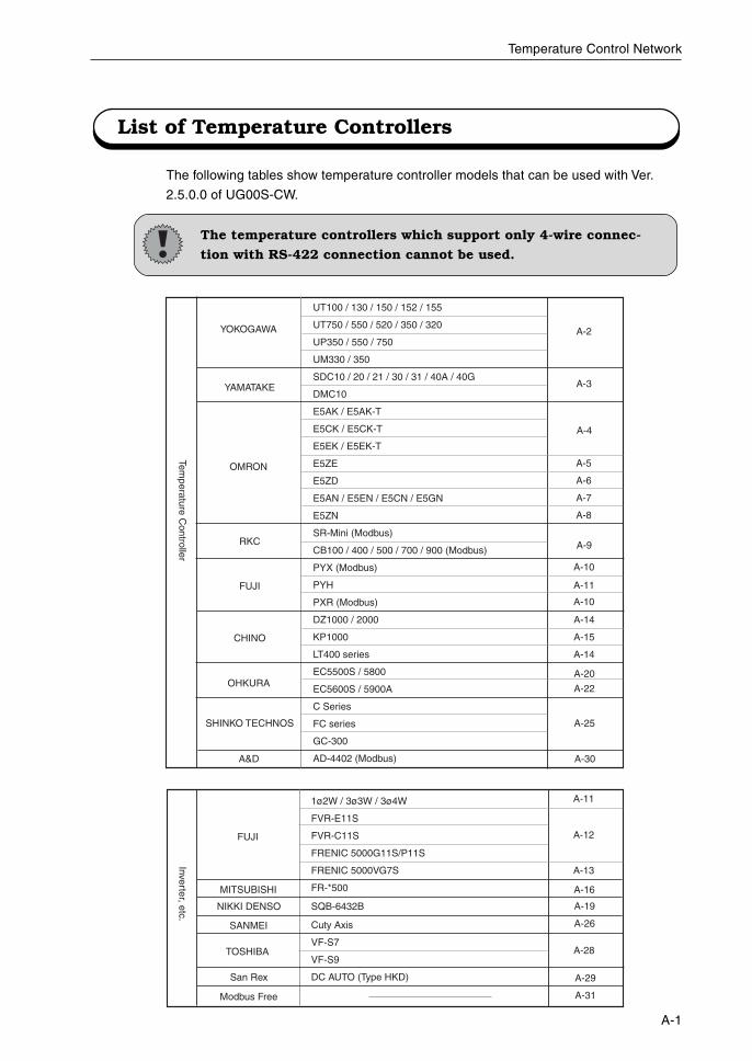
List of Temperature Controllers
The temperature controllers which support only 4-wire connec-
tion with RS-422 connection cannot be used.
The following tables show temperature controller models that can be used with Ver.
2.5.0.0 of UG00S-CW.
YOKOGAWA
YAMATAKE
OMRON
RKC
FUJI
CHINO
SHINKO TECHNOS
Temperature C
ontroller
OHKURA
A&D
UT100 / 130 / 150 / 152 / 155
UT750 / 550 / 520 / 350 / 320
UP350 / 550 / 750
UM330 / 350
SDC10 / 20 / 21 / 30 / 31 / 40A / 40G
DMC10
E5AK / E5AK-T
E5CK / E5CK-T
E5EK / E5EK-T
E5ZE
E5ZD
E5AN / E5EN / E5CN / E5GN
E5ZN
SR-Mini (Modbus)
CB100 / 400 / 500 / 700 / 900 (Modbus)
PYX (Modbus)
PYH
PXR (Modbus)
DZ1000 / 2000
KP1000
LT400 series
EC5500S / 5800
EC5600S / 5900A
C Series
FC series
GC-300
AD-4402 (Modbus)
A-2
A-3
A-4
A-5
A-6
A-7
A-8
A-9
A-11
A-10
A-10
A-14
A-15
A-14
A-25
A-20
A-22
A-30
A-11
A-29
A-31Modbus Free
TOSHIBA
FUJI
MITSUBISHI
SANMEI
San Rex
A-28
NIKKI DENSO
1ø2W / 3ø3W / 3ø4W
FVR-E11S
FVR-C11S
FRENIC 5000G11S/P11S
FRENIC 5000VG7S
FR-*500
SQB-6432B
Cuty Axis
VF-S7
VF-S9
DC AUTO (Type HKD)
A-16
A-12
A-13
Inverter, etc.
A-19
A-26
A-2
Temperature Control Network
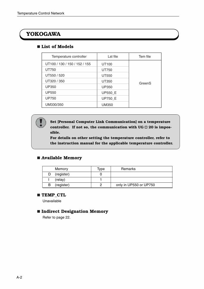
YOKOGAWA
List of Models
Set [Personal Computer Link Communication] on a temperature
controller. If not so, the communication with UG 20 is impos-
sible.
For details on other setting the temperature controller, refer to
the instruction manual for the applicable temperature controller.
Available Memory
TEMP_CTLUnavailable
Indirect Designation MemoryRefer to page 22.
Memory Type Remarks
D (register) 0
I (relay) 1
B (register) 2 only in UP550 or UP750
UT100 / 130 / 150 / 152 / 155
UT750
UT550 / 520
UT320 / 350
UP350
UP550
UP750
UM330/350
UT100
UT750
UT550
UT350
UP350
UP550_E
UP750_E
UM350
GreenS
Lst file Tem fileTemperature controller
A-3
Temperature Control Network
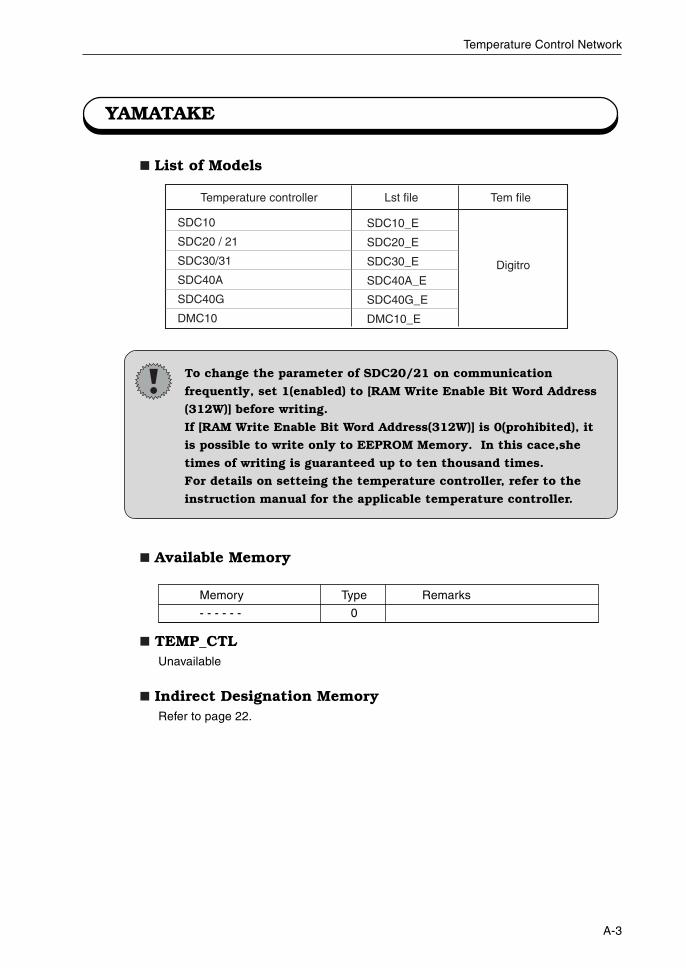
YAMATAKE
SDC10
SDC20 / 21
SDC30/31
SDC40A
SDC40G
DMC10
SDC10_E
SDC20_E
SDC30_E
SDC40A_E
SDC40G_E
DMC10_E
Digitro
Lst file Tem fileTemperature controller
List of Models
Available Memory
TEMP_CTLUnavailable
Indirect Designation MemoryRefer to page 22.
To change the parameter of SDC20/21 on communication
frequently, set 1(enabled) to [RAM Write Enable Bit Word Address
(312W)] before writing.
If [RAM Write Enable Bit Word Address(312W)] is 0(prohibited), it
is possible to write only to EEPROM Memory. In this cace,she
times of writing is guaranteed up to ten thousand times.
For details on setteing the temperature controller, refer to the
instruction manual for the applicable temperature controller.
Memory Type Remarks
- - - - - - 0
A-4
Temperature Control Network
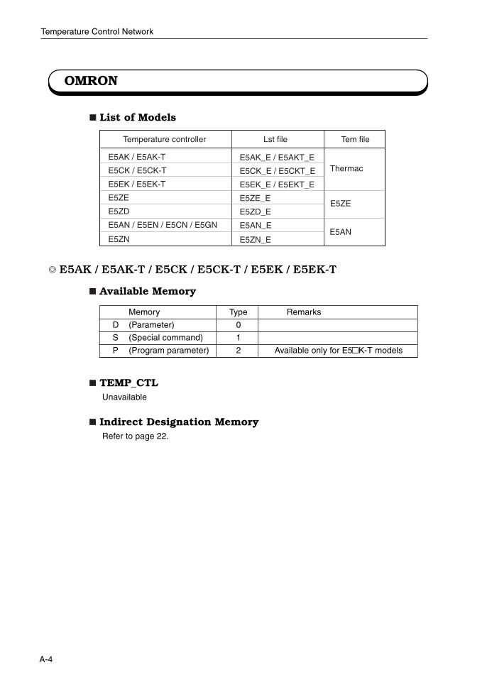
OMRON
List of Models
E5AK / E5AK-T / E5CK / E5CK-T / E5EK / E5EK-T
Available Memory
TEMP_CTLUnavailable
Indirect Designation MemoryRefer to page 22.
Memory Type Remarks
D (Parameter) 0
S (Special command) 1
P (Program parameter) 2 Available only for E5 K-T models
E5AK / E5AK-T
E5CK / E5CK-T
E5EK / E5EK-T
E5ZE
E5ZD
E5AN / E5EN / E5CN / E5GN
E5ZN
E5AK_E / E5AKT_E
E5CK_E / E5CKT_E
E5EK_E / E5EKT_E
E5ZE_E
E5ZD_E
E5AN_E
E5ZN_E
Thermac
Lst file Tem fileTemperature controller
E5AN
E5ZE
A-5
Temperature Control Network
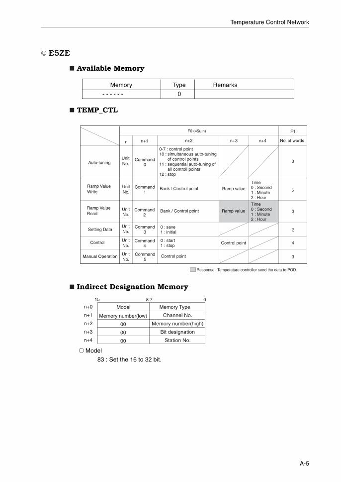
E5ZE
Available Memory
TEMP_CTL
Indirect Designation Memory
Model
83 : Set the 16 to 32 bit.
F0 (=$u n)
n n+1 n+2 No. of words
F1
3
5
n+3 n+4
3
3
4
3
Auto-tuning
Ramp Value Write
UnitNo.
Command0
Command1
0-7 : control point10 : simultaneous auto-tuning
of control points11 : sequential auto-tuning of
all controll points12 : stop
UnitNo.
Ramp Value Read
Setting Data
Control
Manual Operation
Bank / Control point
0 : save1 : initial
0 : start1 : stop
Control point
Bank / Control point
Ramp valueTime0 : Second1 : Minute2 : Hour
UnitNo.
Command2
Ramp value
Time0 : Second1 : Minute2 : Hour
Command3
Command4
Command5
UnitNo.
UnitNo.
UnitNo.
Control point
Response : Temperature controller send the data to POD.
Model Memory Type
Memory number(low)
00
00
00
Channel No.
Memory number(high)
Bit designation
Station No.
n+0
n+1
n+2
n+3
n+4
15 8 7 0
Memory Type Remarks
- - - - - - 0
A-6
Temperature Control Network
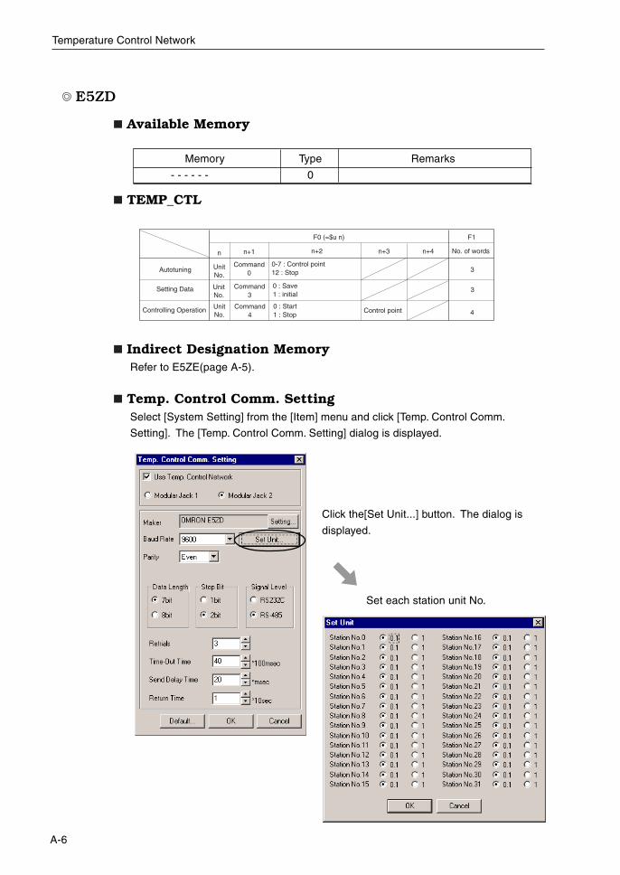
E5ZD
Available Memory
TEMP_CTL
Indirect Designation MemoryRefer to E5ZE(page A-5).
Temp. Control Comm. SettingSelect [System Setting] from the [Item] menu and click [Temp. Control Comm.
Setting]. The [Temp. Control Comm. Setting] dialog is displayed.
F0 (=$u n)
n n+1 n+2 No. of words
F1
3
4Control point
n+3 n+4
3
Autotuning
Setting Data
UnitNo.
Command0
Command3
0-7 : Control point12 : Stop
UnitNo.
Controlling Operation
0 : Save1 : initial
0 : Start1 : Stop
UnitNo.
Command4
Memory Type Remarks
- - - - - - 0
Click the[Set Unit...] button. The dialog is
displayed.
Set each station unit No.
A-7
Temperature Control Network
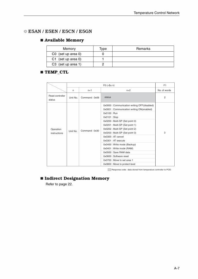
E5AN / E5EN / E5CN / E5GN
Available Memory
TEMP_CTL
Indirect Designation MemoryRefer to page 22.
Read controller
status
Operation
instructions
Unit No. Command : 0x06
Command : 0x30
status
0x0000 : Communication writing OFF(disabled)
0x0001 : Communication writing ON(enabled)
0x0100 : Run
0x0101 : Stop
0x0200 : Multi-SP (Set point 0)
0x0201 : Multi-SP (Set point 1)
0x0202 : Multi-SP (Set point 2)
0x0203 : Multi-SP (Set point 3)
0x0300 : AT cancel
0x0301 : AT execute
0x0400 : Write mode (Backup)
0x0401 : Write mode (RAM)
0x0500 : Save RAM data
0x0600 : Software reset
0x0700 : Move to set area 1
0x0800 : Move to protect level
F0 (=$u n)
n n+1 n+2 No. of words
F1
2
Unit No.3
Response code : data stored from temperature controller to POD.
Memory Type Remarks
C0 (set up area 0) 0
C1 (set up area 0) 1
C3 (set up area 1) 2
A-8
Temperature Control Network
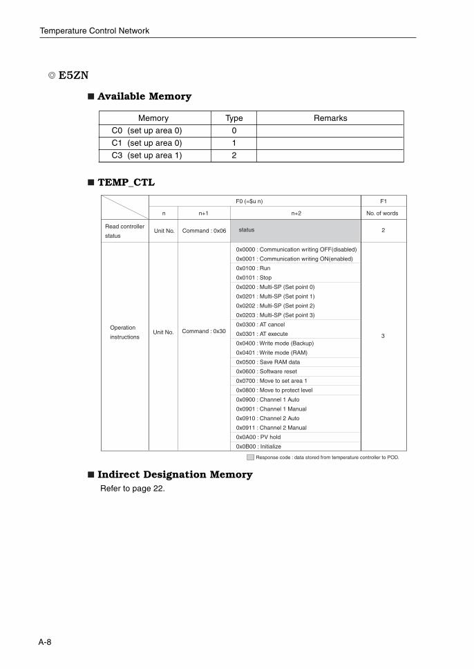
E5ZN
Available Memory
TEMP_CTL
Indirect Designation MemoryRefer to page 22.
Memory Type Remarks
C0 (set up area 0) 0
C1 (set up area 0) 1
C3 (set up area 1) 2
Read controller
status
Operation
instructions
Unit No. Command : 0x06
Command : 0x30
status
0x0000 : Communication writing OFF(disabled)
0x0001 : Communication writing ON(enabled)
0x0100 : Run
0x0101 : Stop
0x0200 : Multi-SP (Set point 0)
0x0201 : Multi-SP (Set point 1)
0x0202 : Multi-SP (Set point 2)
0x0203 : Multi-SP (Set point 3)
0x0300 : AT cancel
0x0301 : AT execute
0x0400 : Write mode (Backup)
0x0401 : Write mode (RAM)
0x0500 : Save RAM data
0x0600 : Software reset
0x0700 : Move to set area 1
0x0800 : Move to protect level
0x0900 : Channel 1 Auto
0x0901 : Channel 1 Manual
0x0910 : Channel 2 Auto
0x0911 : Channel 2 Manual
0x0A00 : PV hold
0x0B00 : Initialize
F0 (=$u n)
n n+1 n+2 No. of words
F1
2
Unit No.3
Response code : data stored from temperature controller to POD.
A-9
Temperature Control Network
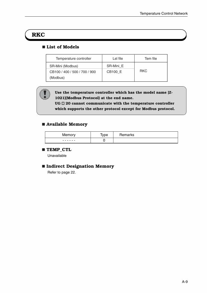
RKC
List of Models
SR-Mini (Modbus)
CB100 / 400 / 500 / 700 / 900
(Modbus)
SR-Mini_E
CB100_E RKC
Lst file Tem fileTemperature controller
Available Memory
TEMP_CTLUnavailable
Indirect Designation MemoryRefer to page 22.
Memory Type Remarks
- - - - - - 0
Use the temperature controller which has the model name [Z-
1021](Modbus Protocol) at the end name.
UG 20 cannot communicate with the temperature controller
which supports the other protocol except for Modbus protocol.
A-10
Temperature Control Network
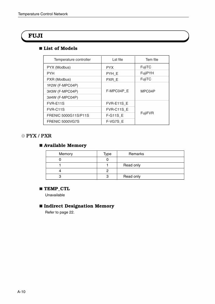
FUJI
List of Models
PYX (Modbus)
PYH
PXR (Modbus)
1 2W (F-MPC04P)
3 3W (F-MPC04P)
3 4W (F-MPC04P)
FVR-E11S
FVR-C11S
FRENIC 5000G11S/P11S
FRENIC 5000VG7S
PYX
PYH_E
PXR_E
FVR-E11S_E
FVR-C11S_E
F-G11S_E
F-VG7S_E
FujiTC
FujiPYH
FujiTC
Lst file Tem fileTemperature controller
F-MPC04P_E MPC04P
FujiFVR
PYX / PXR
Available Memory
TEMP_CTLUnavailable
Indirect Designation MemoryRefer to page 22.
Memory Type Remarks
0 0
1 1 Read only
4 2
3 3 Read only
A-11
Temperature Control Network
Control message Station number Command : 0
F0 (=$u n)n n+1 No. of words
F1
2
If any number other than "0" is set for n+1 memory, an error will be output to system memory.(For details on system memory, refer to page 25.)
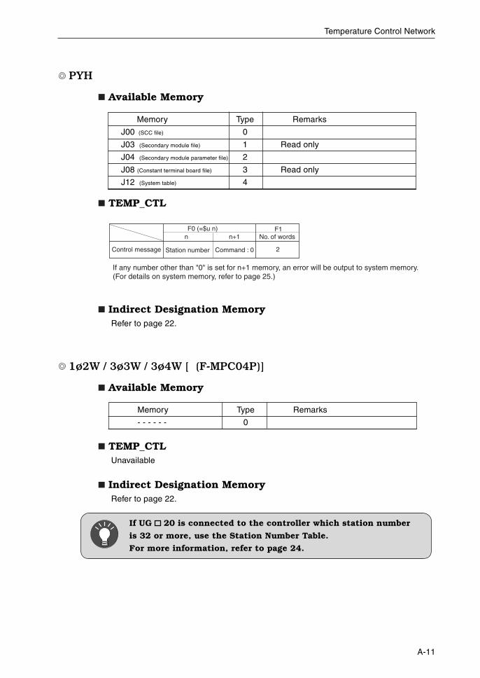
PYH
Available Memory
TEMP_CTL
Indirect Designation MemoryRefer to page 22.
1ø2W / 3ø3W / 3ø4W [ (F-MPC04P)]
Available Memory
TEMP_CTLUnavailable
Indirect Designation MemoryRefer to page 22.
Memory Type Remarks
- - - - - - 0
If UG 20 is connected to the controller which station number
is 32 or more, use the Station Number Table.
For more information, refer to page 24.
Memory Type Remarks
J00 (SCC file) 0
J03 (Secondary module file) 1 Read only
J04 (Secondary module parameter file) 2
J08 (Constant terminal board file) 3 Read only
J12 (System table) 4
A-12
Temperature Control Network
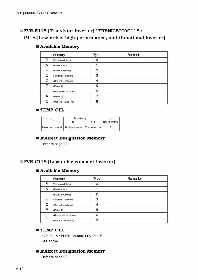
FVR-E11S [Transistor inverter] / FRENIC5000G11S /
P11S [Low-noise, high-performance, multifunctional inverter]
Available Memory
TEMP_CTL
Indirect Designation MemoryRefer to page 22.
FVR-C11S [Low-noise compact inverter]
Available Memory
TEMP_CTLFVR-E11S / FRENIC5000G11S / P11S
See above.
Indirect Designation MemoryRefer to page 22.
Memory Type Remarks
S (Command data) 0
M (Monitor data) 1
F (Basic functions) 2
E (Terminal functions) 3
C (Control functions) 4
P (Motor 1) 5
H (High-level functions) 6
A (Motor 2) 7
O (Optional functions) 8
Reset command Station number Command : 0
F0 (=$u n)n n+1 No. of words
F1
2
Memory Type Remarks
S (Command data) 0
M (Monitor data) 1
F (Basic functions) 2
E (Terminal functions) 3
C (Control functions) 4
P (Motor 1) 5
H (High-level functions) 6
O (Optional functions) 8
A-13
Temperature Control Network
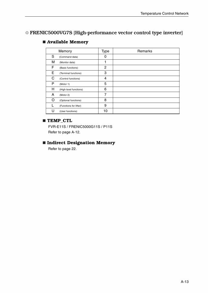
FRENIC5000VG7S [High-performance vector control type inverter]
Available Memory
TEMP_CTLFVR-E11S / FRENIC5000G11S / P11S
Refer to page A-12.
Indirect Designation MemoryRefer to page 22.
Memory Type Remarks
S (Command data) 0
M (Monitor data) 1
F (Basic functions) 2
E (Terminal functions) 3
C (Control functions) 4
P (Motor 1) 5
H (High-level functions) 6
A (Motor 2) 7
O (Optional functions) 8
L (Functions for lifter) 9
U (User functions) 10
A-14
Temperature Control Network
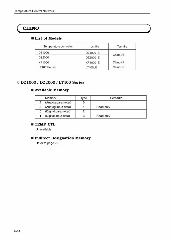
CHINO
List of Models
DZ1000 / DZ2000 / LT400 Series
Available Memory
TEMP_CTLUnavailable
Indirect Designation MemoryRefer to page 22.
Memory Type Remarks
4 (Analog parameter) 0
3 (Analog input data) 1 Read only
0 (Digital parameter) 2
1 (Digital input data) 3 Read only
DZ1000
DZ2000
KP1000
LT400 Series
DZ1000_E
DZ2000_E
KP1000_E
LT400_E
ChinoDZ
ChinoKP
ChinoDZ
Lst file Tem fileTemperature controller
A-15
Temperature Control Network
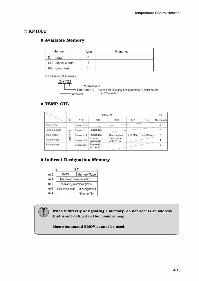
KP1000
Available Memory
TEMP_CTL
Indirect Designation Memory
When indirectly designating a memory, do not access an address
that is not defined in the memory map.
Macro command BMOV cannot be used.
Memory Type
0
1
2
Remarks
D (data)
DN (specific data)
PG (program)
Expression of address
XXYYZZ
AddressParameter 1
Parameter 2* When there is only one parameter, it must be set as “Parameter 1”.
Alarm reset
Pattern select
Step repeat
Pattern copy
Pattern clear
Command: 0
Command: 1
Command: 2
Command: 3
Command: 4
Pattern No.
Pattern No.
Pattern No.(00 : ALL)
F0 (=$u n)
n n+1 n+2 No. of words
F1
2
3
6
4
3
Starting step End step Repeat times
n+3 n+4 n+5
Sta
tion
No.
Source pattern No.
Destination pattern No.
0x83 Memory Typen+0
n+1
n+2
n+3
n+4
15 8 7 0
Memory number (high)
Memory number (low)
Bit designationStation No.
Extension code
A-16
Temperature Control Network
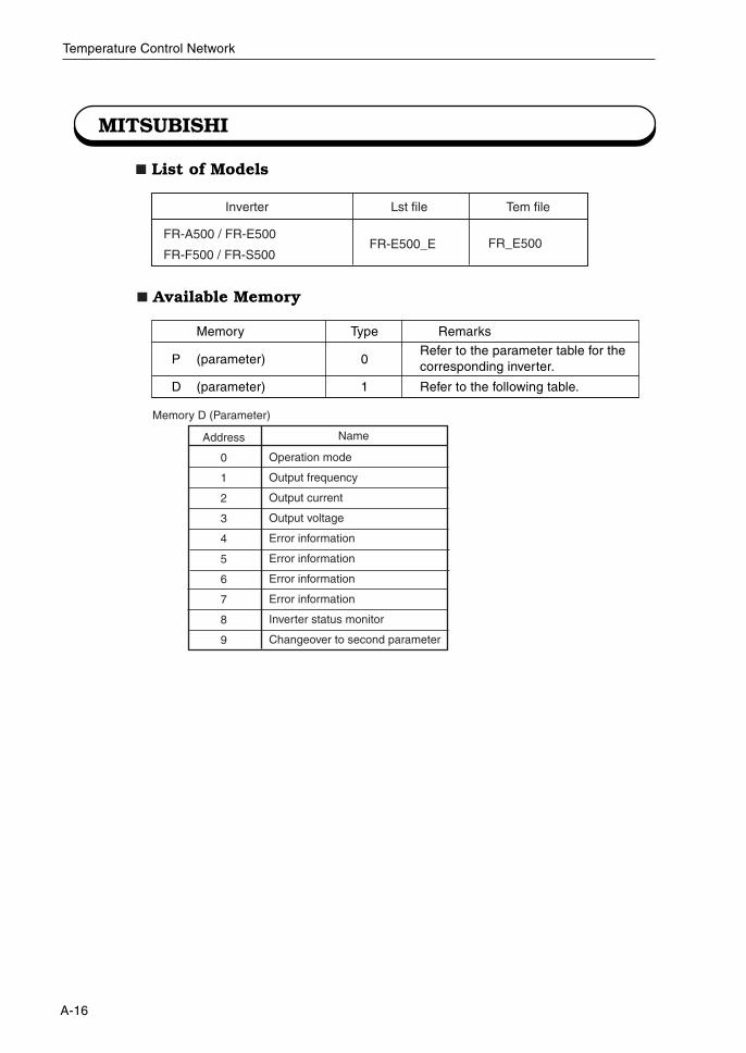
MITSUBISHI
List of Models
FR-A500 / FR-E500
FR-F500 / FR-S500FR-E500_E FR_E500
Lst file Tem fileInverter
Available Memory
Memory Type Remarks
P (parameter) 0Refer to the parameter table for thecorresponding inverter.
D (parameter) 1 Refer to the following table.
Address
0
1
2
3
4
5
6
7
8
9
Operation mode
Output frequency
Output current
Output voltage
Error information
Error information
Error information
Error information
Inverter status monitor
Changeover to second parameter
Name
Memory D (Parameter)
A-17
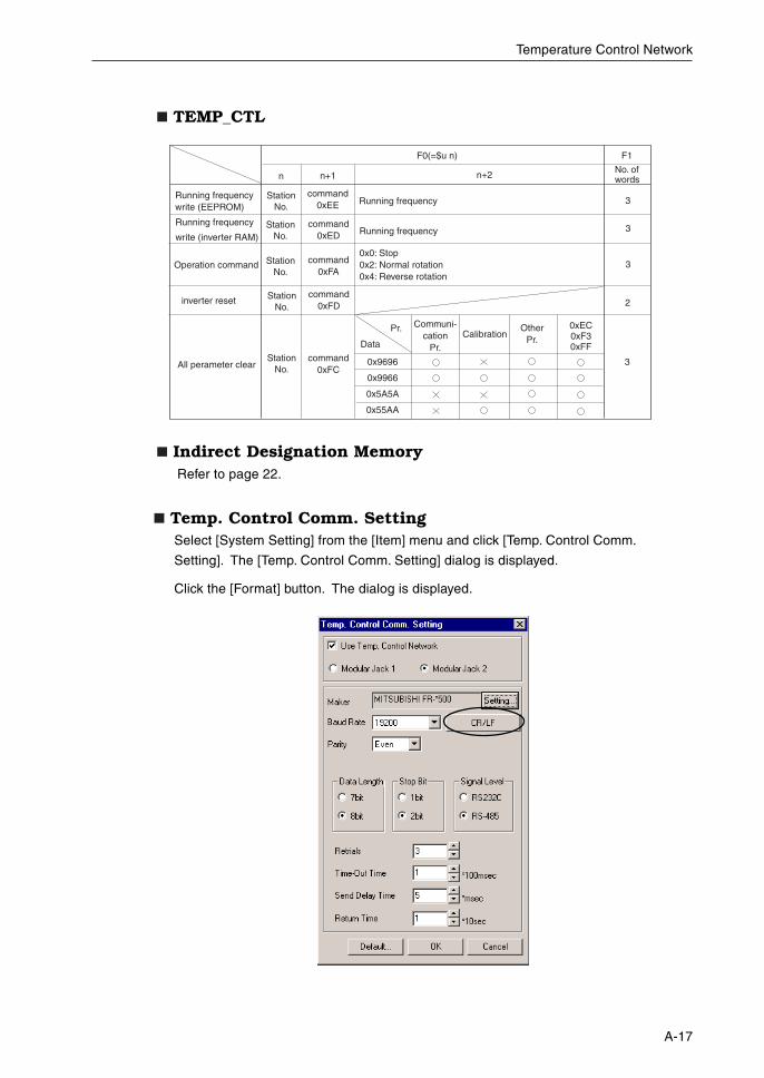
Temperature Control Network
Temp. Control Comm. SettingSelect [System Setting] from the [Item] menu and click [Temp. Control Comm.
Setting]. The [Temp. Control Comm. Setting] dialog is displayed.
Click the [Format] button. The dialog is displayed.
Running frequencywrite (EEPROM)
Running frequency
write (inverter RAM)
StationNo.
command0xEE
command0xED
Running frequency
F0(=$u n)
n n+1 n+2 No. of words
F1
3
StationNo. 2inverter reset
Running frequency
0x0: Stop0x2: Normal rotation0x4: Reverse rotation
Communi-cation
Pr.
StationNo.
Operation command command0xFA
StationNo.
command0xFD
3
3
All perameter clearcommand
0xFC
CalibrationOther
Pr.
0xEC0xF30xFF
StationNo.
Pr.
Data
0x9696
0x9966
0x5A5A
0x55AA
3
TEMP_CTL
Indirect Designation MemoryRefer to page 22.
A-18
Temperature Control Network
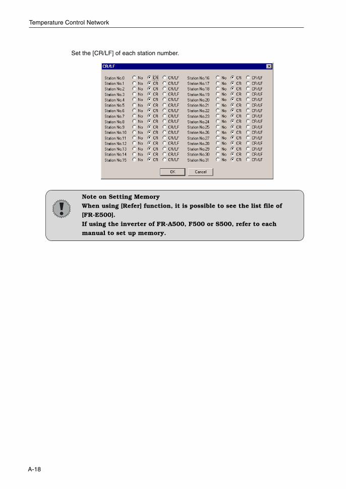
Set the [CR/LF] of each station number.
Note on Setting Memory
When using [Refer] function, it is possible to see the list file of
[FR-E500].
If using the inverter of FR-A500, F500 or S500, refer to each
manual to set up memory.
A-19
Temperature Control Network
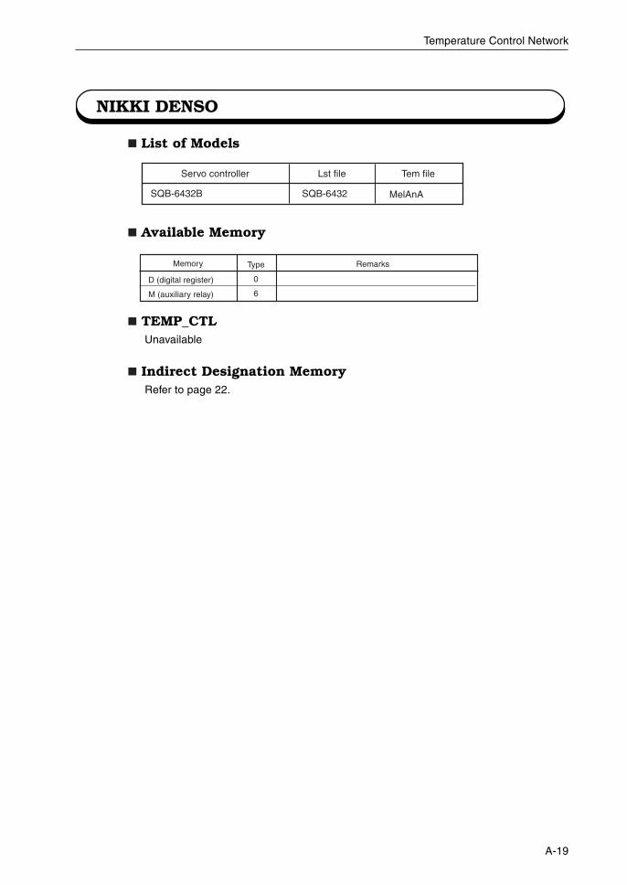
NIKKI DENSO
List of Models
Available Memory
TEMP_CTLUnavailable
Indirect Designation MemoryRefer to page 22.
SQB-6432B SQB-6432 MelAnA
Lst file Tem fileServo controller
Memory Type
0
6
Remarks
D (digital register)
M (auxiliary relay)
A-20
Temperature Control Network
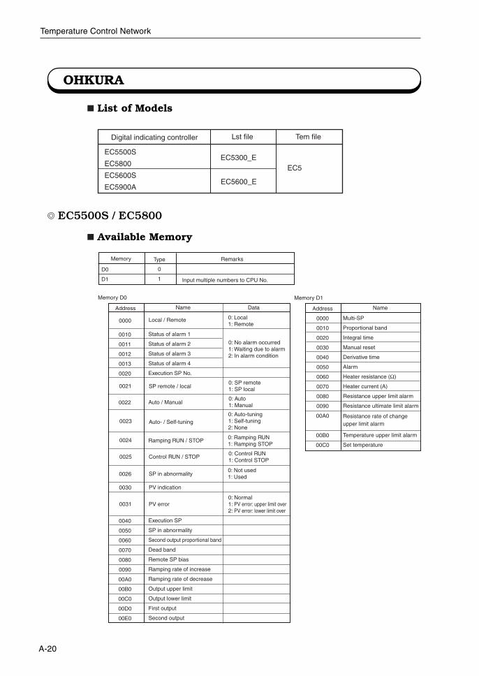
OHKURA
List of Models
EC5500S / EC5800
Available Memory
EC5500S
EC5800
EC5600S
EC5900A
Lst file Tem fileDigital indicating controller
EC5EC5300_E
EC5600_E
D0
D1
Memory Type
0
1
Remarks
Input multiple numbers to CPU No.
Address
Local / Remote
Name
Memory D0
Data
0: No alarm occurred1: Waiting due to alarm2: In alarm condition
0: Local1: Remote
0: SP remote1: SP local
0: Auto1: Manual
0: Auto-tuning1: Self-tuning2: None
0: Ramping RUN1: Ramping STOP
0: Control RUN1: Control STOP
0: Not used1: Used
Status of alarm 1
Status of alarm 2
Status of alarm 3
Status of alarm 4
Execution SP No.
0010
0011
0012
0013
0020
0021 SP remote / local
Auto / Manual0022
Auto- / Self-tuning0023
Ramping RUN / STOP0024
Control RUN / STOP0025
SP in abnormality0026
PV indication0030
PV error0: Normal1: PV error: upper limit over2: PV error: lower limit over
Execution SP
SP in abnormality
Second output proportional band
Dead band
Remote SP bias
Ramping rate of increase
Ramping rate of decrease
Output upper limit
Output lower limit
First output
Second output
0040
0050
0060
0070
0080
0090
00A0
00B0
00C0
00D0
00E0
0031
Address
0000
0010
0020
0030
0040
0050
0060
0070
0080
0090
00A0
00B0
00C0
Multi-SP
Proportional band
Integral time
Manual reset
Derivative time
Alarm
Heater resistance (Ω)
Heater current (A)
Resistance upper limit alarm
Resistance ultimate limit alarm
Temperature upper limit alarm
Set temperature
Name
Memory D1
0000
Resistance rate of change upper limit alarm
A-21
Temperature Control Network
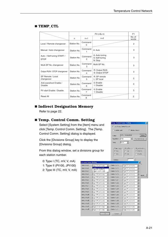
TEMP_CTL
Indirect Designation MemoryRefer to page 22.
Temp. Control Comm. SettingSelect [System Setting] from the [Item] menu and
click [Temp. Control Comm. Setting]. The [Temp.
Control Comm. Setting] dialog is displayed.
Click the [Divisions Group] key to display the
[Divisions Group] dialog.
From this dialog window, set a divisions group for
each station number.
0: Type I (TC, mV, V, mA)
1: Type II (Pt100, JPt100)
2: Type III (TC, mV, V, mA)
Local / Remote changeover
Manual / Auto changeover
Station No.Command
0
Command1
A: Auto
F0 (=$u n)
n n+1 n+2No. of words
F1
2
Station No. 3Multi-SP No. changeover Multi-SP No.
Station No.
Command3
3
Output RUN / STOP changeover Command4
Station No.
3
Auto- / Self-tuning START /
STOPCommand
2
A: Auto-tuningS: Self-tuningN: Stop
Station No. 3
SP Remote / Local changeover
Anti-overshoot Enable / Disable
PV start Enable / Disable
Reset All
Station No.
Station No.
Station No.
Station No.
Command5
Command6
Command7
Command8
R: Output RUNS: Output STOP
R: SP remoteL: SP local
0: Enable1: Disable
0: Enable1: Disable
3
3
2
3
A-22
Temperature Control Network
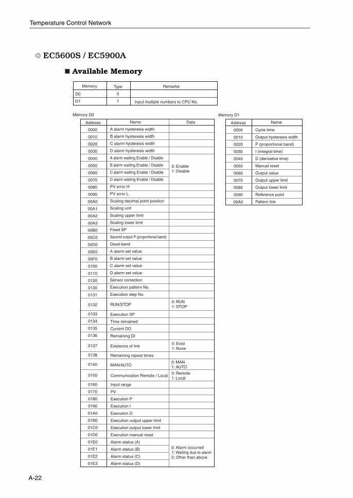
EC5600S / EC5900A
Available Memory
D0
D1
Memory Type
0
1
Remarks
Input multiple numbers to CPU No.
Address
A alarm hysteresis width
B alarm hysteresis width
C alarm hysteresis width
D alarm hysteresis width
A alarm waiting Enable / Disable
B alarm waiting Enable / Disable
C alarm waiting Enable / Disable
D alarm waiting Enable / Disable
PV error H
PV error L
Scaling decimal point position
Scaling unit
Scaling upper limit
Scaling lower limit
Fixed SP
Second output P (proportional band)
Dead band
A alarm set value
B alarm set value
C alarm set value
D alarm set value
Sensor correction
Execution pattern No.
Execution step No.
Name
Memory D0
Data
0: Enable1: Disable
Address
0000
0010
0020
0030
0040
0050
0060
0070
0080
0090
00A0
Cycle time
Output hysteresis width
P (proportional band)
I (integral time)
D (derivative time)
Manual reset
Output value
Output upper limit
Output lower limit
Reference point
Pattern link
Name
Memory D1
0000
0010
0020
0030
0040
0050
0060
0070
0080
0090
00A0
00A1
00A2
00A3
00B0
00C0
00D0
00E0
00F0
0100
0110
0120
0130
0131
Execution SP
Time remained
Current DO
Remaining DI
Remaining repeat times
0: RUN1: STOP
0: Exist1: None
0138
0137 Existence of link
0133
0134
0135
0136
0132 RUN/STOP
Input range
PV
Execution P
Execution I
Execution D
Execution output upper limit
Execution output lower limit
Execution manual reset
Alarm status (A)
Alarm status (B)
Alarm status (C)
Alarm status (D)
MAN/AUTO0: MAN1: AUTO
0: Remote1: Local
Communication Remote / Local
0160
0170
0180
0190
01A0
01B0
01C0
01D0
01E0
01E1
01E2
01E3
0150
0140
0: Alarm occurred1: Waiting due to alarm2: Other than above
A-23
Temperature Control Network
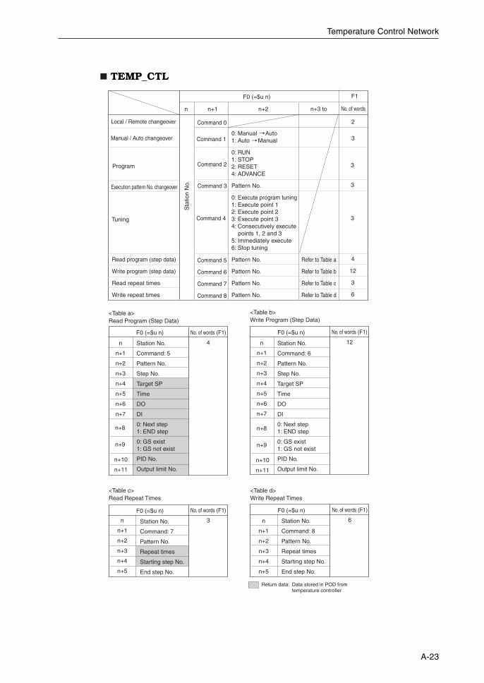
TEMP_CTL
Local / Remote changeover Command 0
0: Manual Auto1: Auto Manual
0: RUN1: STOP2: RESET4: ADVANCE
Pattern No.
0: Execute program tuning1: Execute point 12: Execute point 23: Execute point 34: Consecutively execute points 1, 2 and 35: Immediately execute6: Stop tuning
Pattern No.
Pattern No.
Pattern No.
Pattern No.
F0 (=$u n)
n n+1 n+2
Refer to Table a
Refer to Table b
Refer to Table c
Refer to Table d
n+3 to No. of words
F1
2
Command 5
Command 6
Command 7
Command 8
Command 4
Command 3
Command 2
Command 1
Program
Manual / Auto changeover
Execution pattern No. changeover
Read program (step data)
Write program (step data)
Read repeat times
Write repeat times
Tuning
3
3
3
3
4
12
3
6
Sta
tion
No.
<Table b> Write Program (Step Data)
Return data: Data stored in POD from temperature controller
<Table a> Read Program (Step Data)
n
n+1
n+2
n+3
n+4
n+5
n+6
n+7
Station No.
Command: 5
Pattern No.
Step No.
Target SP
Time
DO
DI
0: Next step1: END step
0: GS exist1: GS not exist
PID No.
Output limit No.
Station No.
Command: 6
Pattern No.
Step No.
Target SP
Time
DO
DI
0: Next step1: END step
0: GS exist1: GS not exist
PID No.
Output limit No.
No. of words (F1)
4
F0 (=$u n)
<Table c> Read Repeat Times
<Table d> Write Repeat Times
n
n+1
n+2
n+3
n+4
n+5
Station No.
Command: 7
Pattern No.
Repeat times
Starting step No.
End step No.
No. of words (F1)
3
F0 (=$u n)
n
n+1
n+2
n+3
n+4
n+5
n+6
n+7
No. of words (F1)
12
F0 (=$u n)
n+8
n+9
n+10
n+11
n+8
n+9
n+10
n+11
n
n+1
n+2
n+3
n+4
n+5
Station No.
Command: 8
Pattern No.
Repeat times
Starting step No.
End step No.
No. of words (F1)
6
F0 (=$u n)

A-24
Temperature Control Network
Indirect Designation MemoryRefer to page 22.
Temp. Control Comm. SettingRefer to page A-21.
A-25
Temperature Control Network
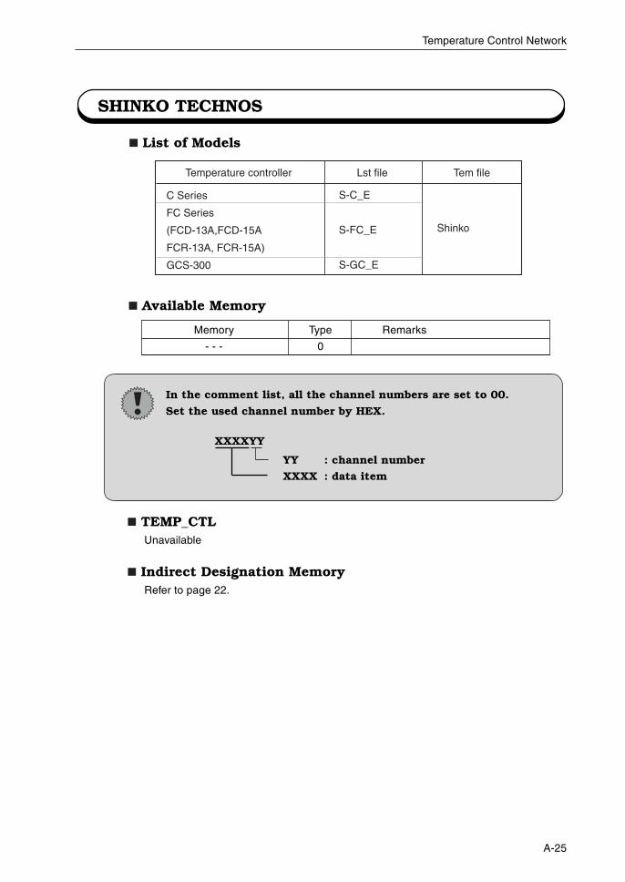
SHINKO TECHNOS
List of Models
Available Memory
C Series
FC Series
(FCD-13A,FCD-15A
FCR-13A, FCR-15A)
GCS-300
S-C_E
S-FC_E
S-GC_E
Shinko
Lst file Tem fileTemperature controller
Memory Type Remarks
- - - 0
TEMP_CTLUnavailable
Indirect Designation MemoryRefer to page 22.
In the comment list, all the channel numbers are set to 00.
Set the used channel number by HEX.
XXXXYY
YY : channel number
XXXX : data item
A-26
Temperature Control Network
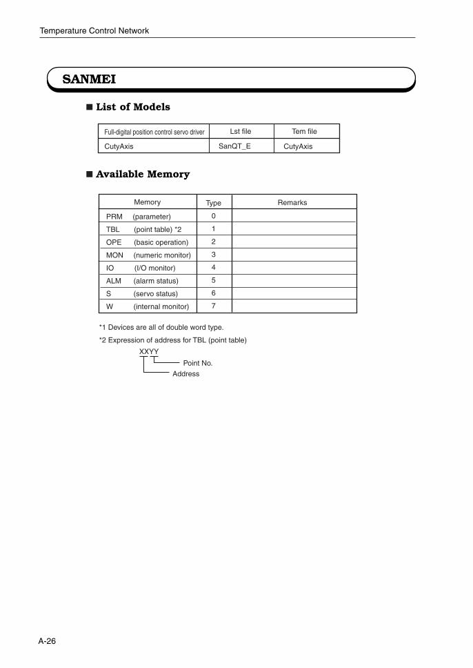
SANMEI
List of Models
Available Memory
CutyAxis SanQT_E
Lst file Tem fileFull-digital position control servo driver
CutyAxis
Memory Type
0
1
2
3
4
5
6
7
Remarks
PRM (parameter)
TBL (point table) *2
OPE (basic operation)
MON (numeric monitor)
IO (I/O monitor)
ALM (alarm status)
S (servo status)
W (internal monitor)
*1 Devices are all of double word type.
*2 Expression of address for TBL (point table)
XXYY
Point No.
Address
A-27
Temperature Control Network
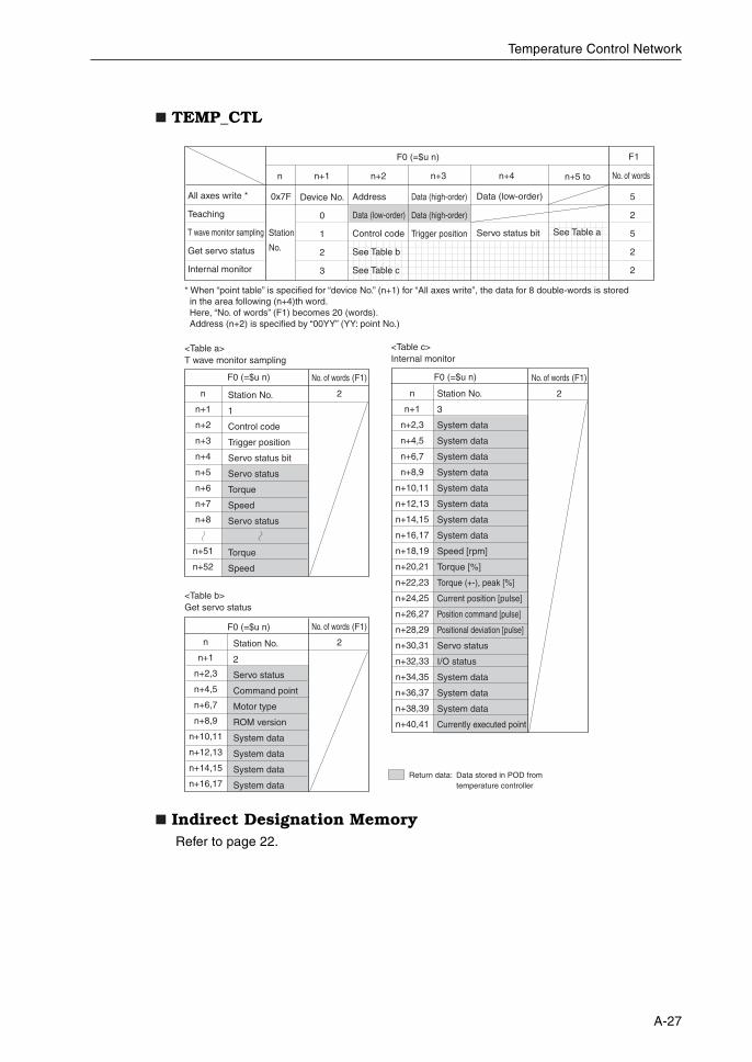
TEMP_CTL
Indirect Designation MemoryRefer to page 22.
<Table c> Internal monitor
n
n+1
n+2,3
n+4,5
n+6,7
n+8,9
n+10,11
n+12,13
n+14,15
n+16,17
n+18,19
n+20,21
n+22,23
n+24,25
n+26,27
n+28,29
n+30,31
n+32,33
n+34,35
n+36,37
n+38,39
n+40,41
Station No.
3
System data
System data
System data
System data
System data
System data
System data
System data
Speed [rpm]
Torque [%]
Torque (+-), peak [%]
Current position [pulse]
Position command [pulse]
Positional deviation [pulse]
Servo status
I/O status
System data
System data
System data
Currently executed point
F0 (=$u n)
All axes write *
Teaching
T wave monitor sampling
Get servo status
Internal monitor
Station
No.
Device No.
0
1
2
3
Address
Data (low-order)
Control code
See Table b
See Table c
F0 (=$u n)
n n+1 n+2
Data (high-order)
Data (high-order)
Trigger position
Data (low-order)
Servo status bit
n+3 n+4 n+5 to
0x7F
No. of words
F1
5
2
5
2
2
Return data: Data stored in POD from temperature controller
See Table a
<Table a> T wave monitor sampling
n
n+1
n+2
n+3
n+4
n+5
n+6
n+7
n+8
n+51
n+52
Station No.
1
Control code
Trigger position
Servo status bit
Servo status
Torque
Speed
Servo status
Torque
Speed
No. of words (F1)
2
No. of words (F1)
2
No. of words (F1)
2
F0 (=$u n)
<Table b> Get servo status
n
n+1
n+2,3
n+4,5
n+6,7
n+8,9
n+10,11
n+12,13
n+14,15
n+16,17
Station No.
2
Servo status
Command point
Motor type
ROM version
System data
System data
System data
System data
F0 (=$u n)
* When “point table” is specified for “device No.” (n+1) for “All axes write”, the data for 8 double-words is stored in the area following (n+4)th word. Here, “No. of words” (F1) becomes 20 (words). Address (n+2) is specified by “00YY” (YY: point No.)
A-28
Temperature Control Network
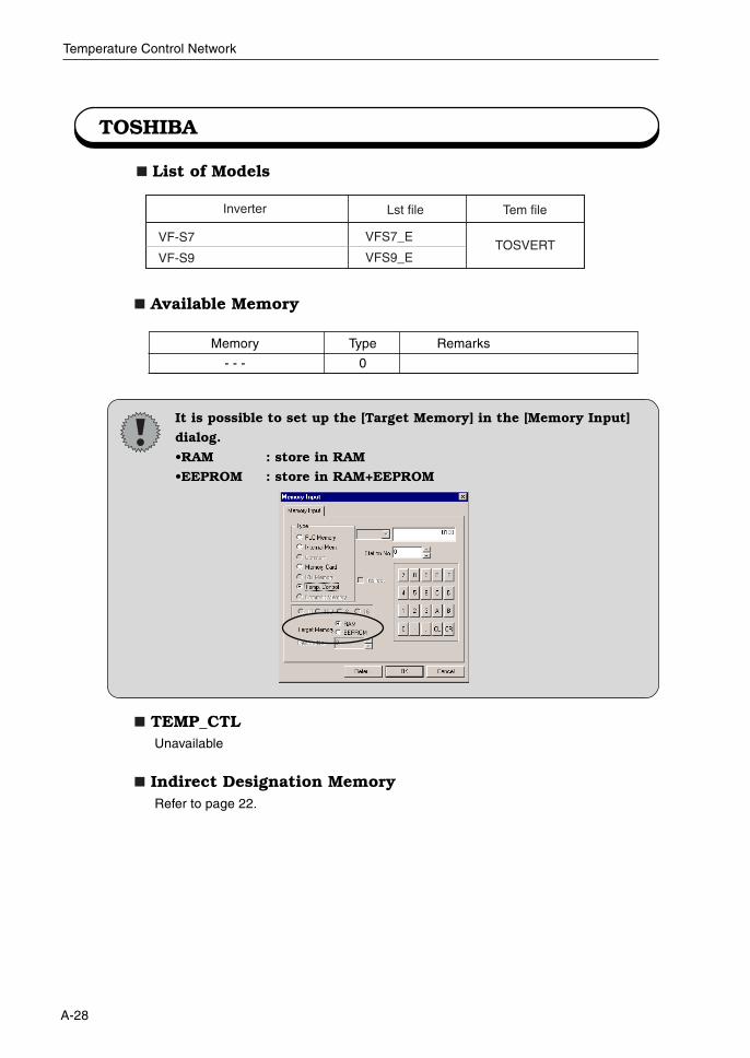
TOSHIBA
List of Models
VF-S7
VF-S9
VFS7_E
VFS9_ETOSVERT
Lst file Tem fileInverter
Available Memory
TEMP_CTLUnavailable
Indirect Designation MemoryRefer to page 22.
Memory Type Remarks
- - - 0
It is possible to set up the [Target Memory] in the [Memory Input]
dialog.
•RAM : store in RAM
•EEPROM : store in RAM+EEPROM
A-29
Temperature Control Network
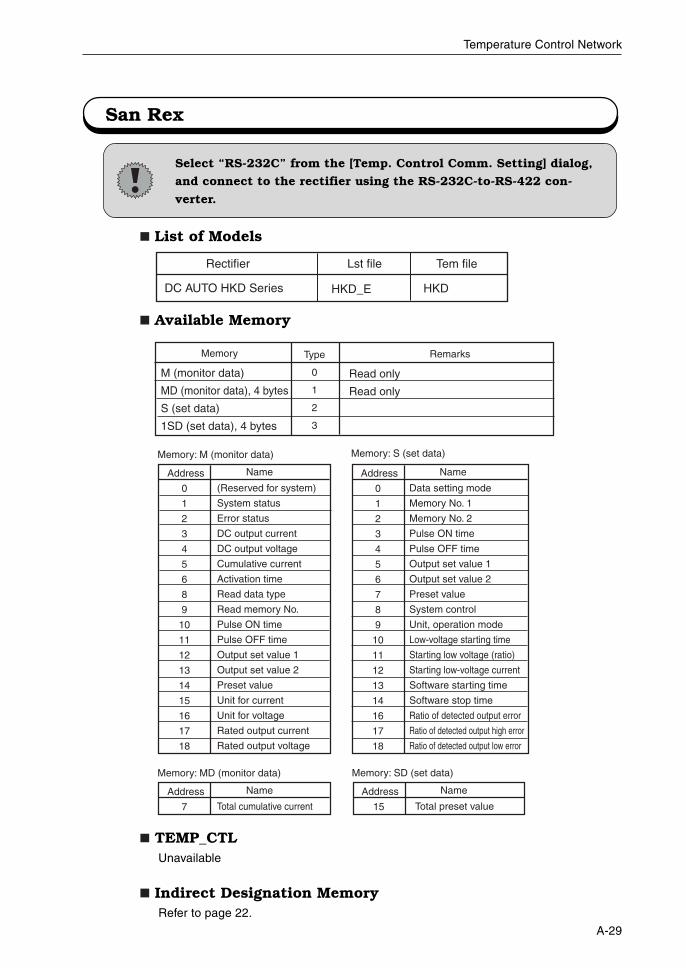
San Rex
List of Models
Available Memory
TEMP_CTLUnavailable
Indirect Designation MemoryRefer to page 22.
DC AUTO HKD Series
Lst file Tem fileRectifier
HKD_E HKD
Select “RS-232C” from the [Temp. Control Comm. Setting] dialog,
and connect to the rectifier using the RS-232C-to-RS-422 con-
verter.
Memory Type
0
1
2
3
Remarks
M (monitor data)
MD (monitor data), 4 bytes
S (set data)
1SD (set data), 4 bytes
Memory: M (monitor data)
Read only
Read only
Address
0
1
2
3
4
5
6
8
9
10
11
12
13
14
15
16
17
18
(Reserved for system)
System status
Error status
DC output current
DC output voltage
Cumulative current
Activation time
Read data type
Read memory No.
Pulse ON time
Pulse OFF time
Output set value 1
Output set value 2
Preset value
Unit for current
Unit for voltage
Rated output current
Rated output voltage
Name
Memory: S (set data)
Address
0
1
2
3
4
5
6
7
8
9
10
11
12
13
14
16
17
18
Data setting mode
Memory No. 1
Memory No. 2
Pulse ON time
Pulse OFF time
Output set value 1
Output set value 2
Preset value
System control
Unit, operation mode
Low-voltage starting time
Starting low voltage (ratio)
Starting low-voltage current
Software starting time
Software stop time
Ratio of detected output error
Ratio of detected output high error
Ratio of detected output low error
Name
Memory: MD (monitor data)
Address
7 Total cumulative current
Name
Memory: SD (set data)
Address
15 Total preset value
Name
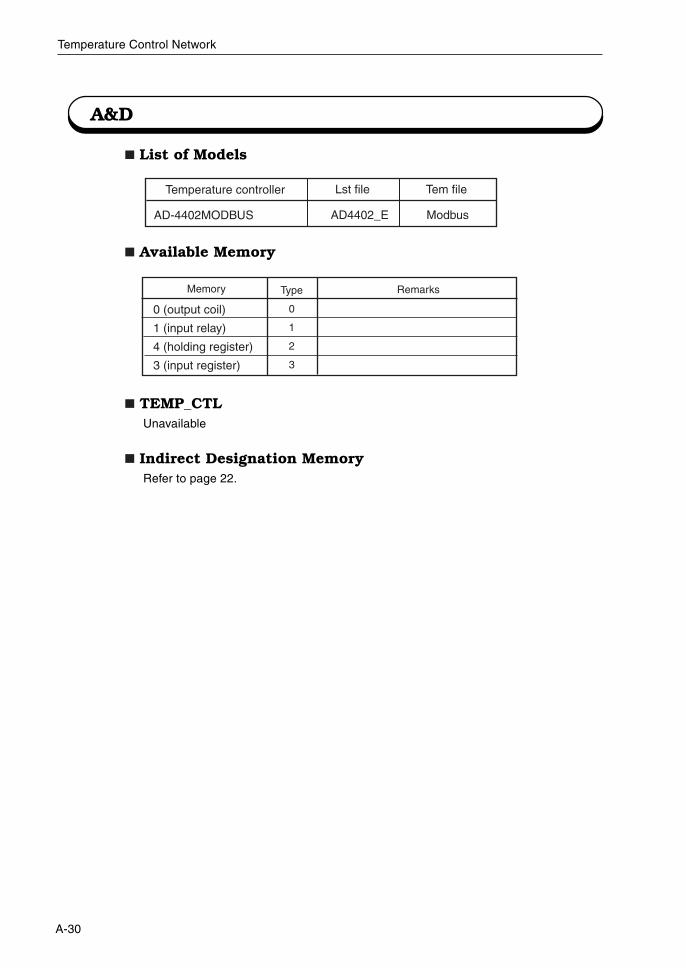
A-30
Temperature Control Network
A&D
List of Models
Available Memory
TEMP_CTLUnavailable
Indirect Designation MemoryRefer to page 22.
AD-4402MODBUS
Lst file Tem fileTemperature controller
AD4402_E Modbus
Memory Type
0
1
2
3
Remarks
0 (output coil)
1 (input relay)
4 (holding register)
3 (input register)
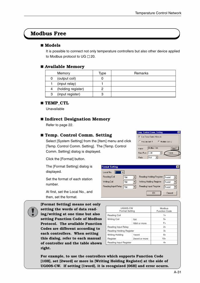
A-31
Temperature Control Network
Modbus Free
ModelsIt is possible to connect not only temperature controllers but also other device applied
to Modbus protocol to UG 20.
Available Memory
TEMP_CTLUnavailable
Indirect Designation MemoryRefer to page 22.
Temp. Control Comm. SettingSelect [System Setting] from the [Item] menu and click
[Temp. Control Comm. Setting]. The [Temp. Control
Comm. Setting] dialog is displayed.
Click the [Format] button.
The [Format Setting] dialog is
displayed.
Set the format of each station
number.
At first, set the Local No., and
then, set the format.
[Format Setting] means not onlysetting the words of data read-ing/writing at one time but alsosetting Function Code of ModbusProtocol. The available FunctionCodes are different according toeach controllers. When settingthis dialog, refer to each manualof controller and the table shownright.
For example, to use the controllers which supports Function Code[10H], set [2word] or more in [Writing Holding Register] at the side ofUG00S-CW. If setting [1word], it is recognized [06H] and error ocurrs.
Memory Type Remarks
0 (output coil) 0
1 (input relay) 1
4 (holding register) 2
3 (input register) 3
ModbusFunction Code
UG00S-CW Format Setting
1bit
16bit or more
Reading Coil
Writing Coil
Reading Input Relay
Reading Holding Register
Writing Holding
Register
Reading Input Register
1H
5H
FH
2H
3H
6H
10H
4H
1word
2word or more

Fuji Electric Co., Ltd.ED & C • EDrive Systems CompanyGate City Ohsaki, East Tower11-2, Osaki 1-chome, Shinagawa-ku, Tokyo, 141-0032, JapanPhone: +81-3-5435-7135~8Fax: +81-3-5435-7456~9
URL http://www.fujielectric.co.jp/kiki/Printed on recycled paper
Information in this manual is subject to change without notice. Printed in Japan 2001-8(H01/H01) F 3 FIS