perfect charging / perfect welding / solar energy perfect charging / perfect welding / solar energy...
TRANSCRIPT

/ Perfect Charging / Perfect Welding / Solar Energy
42,0426,0114,EN 011-19052014
TPS 320i / 400i / 500iTPS 400i LSC ADV
Operating Instructions
MIG/MAG Power sourceEN

0

EN
Dear reader,
Introduction Thank you for the trust you have placed in our company and congratulations on buying this high-quality Fronius product. These instructions will help you familiarise yourself with the product. Reading the instructions carefully will enable you to learn about the many different features it has to offer. This will allow you to make full use of its advantages.
Please also note the safety rules to ensure greater safety when using the product. Careful handling of the product will repay you with years of safe and reliable operation. These are essential prerequisites for excellent results.
1

2

EN
Contents
Safety rules ................................................................................................................................................ 7
General information 19
General ...................................................................................................................................................... 21Device concept ..................................................................................................................................... 21Functional principle ............................................................................................................................... 21Application areas .................................................................................................................................. 21Warning notices on the device.............................................................................................................. 22
Welding processes, processes and welding characteristics ...................................................................... 23General ................................................................................................................................................. 23Welding characteristics ......................................................................................................................... 23Summary of MIG/MAG pulse welding................................................................................................... 23Summary of MIG/MAG standard synergic welding ............................................................................... 23Summary of the PMC process .............................................................................................................. 24Summary of the LSC / LSC Advanced process .................................................................................... 24Summary of the CMT process .............................................................................................................. 24
System components .................................................................................................................................. 25General ................................................................................................................................................. 25Overview............................................................................................................................................... 25
Controls, connections and mechanical components 27
Control panel.............................................................................................................................................. 29General ................................................................................................................................................. 29Safety.................................................................................................................................................... 29Control panel......................................................................................................................................... 29
Connections, switches and mechanical components ................................................................................ 31TPS 320i / 400i / 500i power source ..................................................................................................... 31
Operating concept 33
Input options .............................................................................................................................................. 35General ................................................................................................................................................. 35Turning/pressing the adjusting dial ....................................................................................................... 35Pressing buttons ................................................................................................................................... 36Pressing on the display......................................................................................................................... 36
Display and status line ............................................................................................................................... 37Display .................................................................................................................................................. 37Status line ............................................................................................................................................. 38
Installation and commissioning 39
Minimum equipment needed for welding task............................................................................................ 41General ................................................................................................................................................. 41MIG/MAG gas-cooled welding .............................................................................................................. 41MIG/MAG water-cooled welding ........................................................................................................... 41
Before installation and commissioning....................................................................................................... 42Safety.................................................................................................................................................... 42Proper use ............................................................................................................................................ 42Setup regulations .................................................................................................................................. 42Mains connection .................................................................................................................................. 42Generator-powered operation............................................................................................................... 43Information on system components ...................................................................................................... 43
Connecting the mains cable....................................................................................................................... 44General ................................................................................................................................................. 44Stipulated mains cables ........................................................................................................................ 44Connecting the mains cable - general .................................................................................................. 44
Commissioning the TPS 320i / 400i / 500i, TPS 400i LSC ADV................................................................ 46Safety.................................................................................................................................................... 46
3

General ................................................................................................................................................. 46TPS 320i / 400i / 500i: Fitting the system components (overview) ....................................................... 47TPS 400i LSC ADV: Fitting the system components (overview) .......................................................... 48Fixing the strain-relief device for the interconnecting hosepack ........................................................... 49Connecting the interconnecting hosepack ............................................................................................ 49Connecting the gas cylinder.................................................................................................................. 50Establishing a ground (earth) connection ............................................................................................. 50Connecting MIG/MAG welding torches to the wire-feed unit ................................................................ 51Other tasks............................................................................................................................................ 52
Welding 53
MIG/MAG modes ....................................................................................................................................... 55General ................................................................................................................................................. 55Symbols and their explanations ............................................................................................................ 552-step mode.......................................................................................................................................... 564-step mode.......................................................................................................................................... 56Special 4-step mode ............................................................................................................................. 57
MIG/MAG welding...................................................................................................................................... 58Safety.................................................................................................................................................... 58MIG/MAG welding - overview ............................................................................................................... 58Switch on the power source.................................................................................................................. 58Setting the welding process and operating mode ................................................................................. 59Selecting the filler metal........................................................................................................................ 60Setting the welding parameters ............................................................................................................ 63Setting the shielding gas flow rate ........................................................................................................ 64MIG/MAG welding................................................................................................................................. 64
EasyJob mode ........................................................................................................................................... 65General ................................................................................................................................................. 65Activating EasyJob mode...................................................................................................................... 65Storing EasyJob operating points ......................................................................................................... 66Retrieving EasyJob operating points .................................................................................................... 67Deleting EasyJob operating points ....................................................................................................... 68
Job mode ................................................................................................................................................... 69General ................................................................................................................................................. 69Store settings as a job .......................................................................................................................... 69Weld job - retrieving a job ..................................................................................................................... 71Renaming a job..................................................................................................................................... 73Deleting a job ........................................................................................................................................ 75
Welding parameters................................................................................................................................... 77Welding parameters for MIG/MAG pulse synergic welding .................................................................. 77Welding parameters for MIG/MAG standard synergic welding ............................................................. 78Explanation of footnotes ....................................................................................................................... 79
Process parameters................................................................................................................................... 80Overview............................................................................................................................................... 80Process parameters for start of welding / end of welding ..................................................................... 80Process parameters for gas setup ........................................................................................................ 82Process parameters for process regulation .......................................................................................... 82R/L adjustment...................................................................................................................................... 83Process parameters for components .................................................................................................... 86
Defaults 87
Defaults...................................................................................................................................................... 89General remarks ................................................................................................................................... 89Overview............................................................................................................................................... 89Setting the language ............................................................................................................................. 90Setting the units .................................................................................................................................... 91Setting date and time ............................................................................................................................ 92
Troubleshooting and maintenance 95
Troubleshooting ......................................................................................................................................... 97General ................................................................................................................................................. 97
4
EN
Safety.................................................................................................................................................... 97Power source - troubleshooting ............................................................................................................ 97
Care, maintenance and disposal ............................................................................................................... 100General ................................................................................................................................................. 100Safety.................................................................................................................................................... 100At every start-up.................................................................................................................................... 100Every 2 months ..................................................................................................................................... 100Every 6 months ..................................................................................................................................... 100Updating firmware................................................................................................................................. 100Disposal ................................................................................................................................................ 100
Appendix 101
Technical data............................................................................................................................................ 103Special voltages.................................................................................................................................... 103TPS 320i ............................................................................................................................................... 104TPS 320i /nc ......................................................................................................................................... 105TPS 320i /600V/nc ................................................................................................................................ 106TPS 320i /MV/nc ................................................................................................................................... 107TPS 400i ............................................................................................................................................... 108TPS 400i /nc ......................................................................................................................................... 109TPS 400i /600V/nc ................................................................................................................................ 110TPS 400i /MV/nc ................................................................................................................................... 111TPS 400i LSC ADV............................................................................................................................... 112TPS 400i LSC ADV /nc ....................................................................................................................... 113TPS 400i LSC ADV /600V/nc.............................................................................................................. 114TPS 400i LSC ADV /MV/nc................................................................................................................. 115TPS 500i ............................................................................................................................................... 116TPS 500i /nc ......................................................................................................................................... 117TPS 500i /600V/nc ................................................................................................................................ 118TPS 500i /MV/nc ................................................................................................................................... 119
Spare parts list: TPS 320i / 400i / 500i....................................................................................................... 120
5

6
EN
Safety rules
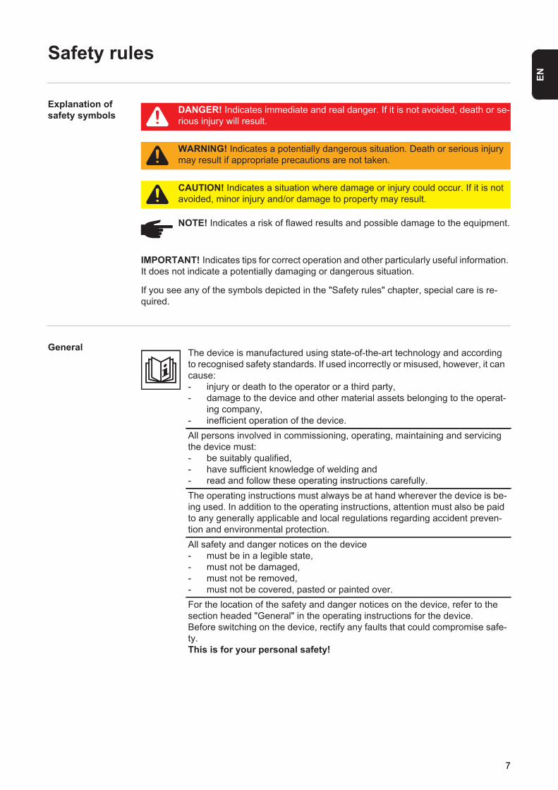
Explanation of safety symbols
If you see any of the symbols depicted in the "Safety rules" chapter, special care is re-quired.
General
DANGER! Indicates immediate and real danger. If it is not avoided, death or se-rious injury will result.
WARNING! Indicates a potentially dangerous situation. Death or serious injury may result if appropriate precautions are not taken.
CAUTION! Indicates a situation where damage or injury could occur. If it is not avoided, minor injury and/or damage to property may result.
NOTE! Indicates a risk of flawed results and possible damage to the equipment.
IMPORTANT! Indicates tips for correct operation and other particularly useful information. It does not indicate a potentially damaging or dangerous situation.
The device is manufactured using state-of-the-art technology and according to recognised safety standards. If used incorrectly or misused, however, it can cause:- injury or death to the operator or a third party,- damage to the device and other material assets belonging to the operat-
ing company,- inefficient operation of the device.All persons involved in commissioning, operating, maintaining and servicing the device must:- be suitably qualified,- have sufficient knowledge of welding and- read and follow these operating instructions carefully.The operating instructions must always be at hand wherever the device is be-ing used. In addition to the operating instructions, attention must also be paid to any generally applicable and local regulations regarding accident preven-tion and environmental protection.All safety and danger notices on the device - must be in a legible state, - must not be damaged, - must not be removed,- must not be covered, pasted or painted over.For the location of the safety and danger notices on the device, refer to the section headed "General" in the operating instructions for the device.Before switching on the device, rectify any faults that could compromise safe-ty.This is for your personal safety!
7

Proper use
Environmental conditions
Obligations of the operator
The device is to be used exclusively for its intended purpose.The device is intended solely for the welding processes specified on the rating plate.Any use above and beyond this purpose is deemed improper. The manufac-turer shall not be held liable for any damage arising from such usage.
Proper use includes:- carefully reading and following all the instructions given in the operating
instructions - studying and obeying all safety and danger notices carefully- performing all stipulated inspection and maintenance work.Never use the device for the following purposes:- Thawing out pipes- Charging batteries- Starting enginesThe device is designed for use in industry and the workshop. The manufactur-er accepts no responsibility for any damage caused through use in a domestic setting.The manufacturer likewise accepts no liability for inadequate or incorrect re-sults.
Operation or storage of the device outside the stipulated area will be deemed as not in accordance with the intended purpose. The manufacturer shall not be held liable for any damage arising from such usage.Ambient temperature range:- during operation: -10 °C to + 40 °C (14 °F to 104 °F)- during transport and storage: -20 °C to +55 °C (-4 °F to 131 °F)Relative humidity:- up to 50% at 40 °C (104 °F)- up to 90% at 20 °C (68 °F)The surrounding air must be free from dust, acids, corrosive gases or sub-stances, etc.Can be used at altitudes of up to 2000 m (6561 ft. 8.16 in.)
The operator must only allow persons to work with the device who: - are familiar with the fundamental instructions regarding safety at work and
accident prevention and have been instructed in how to use the device- have read and understood these operating instructions, especially the
section "safety rules", and have confirmed as much with their signatures - are trained to produce the required results.Checks must be carried out at regular intervals to ensure that operators are working in a safety-conscious manner.
8

EN
Obligations of personnel
Mains connection
Residual current protective device
Protecting your-self and others
Before using the device, all persons instructed to do so undertake:- to observe the basic instructions regarding safety at work and accident
prevention- to read these operating instructions, especially the "Safety rules" section
and sign to confirm that they have understood them and will follow them.Before leaving the workplace, ensure that people or property cannot come to any harm in your absence.
Devices with a higher rating may affect the energy quality of the mains due to their current input.This may affect a number of device types in terms of:- connection restrictions- criteria with regard to the maximum permissible mains impedance *)- criteria with regard to the minimum short-circuit power requirement *)
*) at the interface with the public gridsee "Technical data"In this case, the plant operator or the person using the device should check whether the device may be connected, where appropriate by discussing the matter with the power supply company.
NOTE! Ensure that the mains connection is earthed properly
Local regulations and national guidelines may require a residual current pro-tective device when connecting equipment to the public grid.The type of residual current protective device recommended by Fronius for the equipment is indicated in the technical data.
RCD
Persons involved with welding expose themselves to numerous risks, e.g.:- flying sparks and hot pieces of metal- arc radiation, which can damage eyes and skin
- hazardous electromagnetic fields, which can endanger the lives of those using cardiac pacemakers
- risk of electrocution from mains current and welding current
- greater noise pollution
9

Noise emission values
Danger from toxic gases and va-pours
- harmful welding fumes and gasesAnyone working on the workpiece while welding is in progress must wear suit-able protective clothing with the following properties:- flame-resistant- insulating and dry- covers the whole body, is undamaged and in good condition- safety helmet- trousers with no turn-upsProtective clothing refers to a variety of different items. Operators should:- protect eyes and face from UV rays, heat and sparks using a protective
visor and regulation filter.- wear regulation protective goggles with side protection behind the protec-
tive visor.- wear stout footwear that provides insulation even in wet conditions.- protect the hands with suitable gloves (electrically insulated and providing
protection against heat).- wear ear protection to reduce the harmful effects of noise and to prevent
injury.Keep all persons, especially children, out of the working area while any devic-es are in operation or welding is in progress. If, however, there are people in the vicinity,- make them aware of all the dangers (risk of dazzling by the arc, injury
from flying sparks, harmful welding fumes, noise, possible risks from mains current and welding current, etc.),
- provide suitable protective equipment or- erect suitable safety screens/curtains.
The device generates a maximum sound power level of <80 dB(A) (ref. 1pW) when idling and in the cooling phase following operation at the maximum per-missible operating point under maximum rated load conditions according to EN 60974-1.It is not possible to provide a workplace-related emission value during welding (or cutting) as this is influenced by both the process and the environment. All manner of different welding parameters come into play, including the welding process (MIG/MAG, TIG welding), the type of power selected (DC or AC), the power range, the type of weld metal, the resonance characteristics of the workpiece, the workplace environment, etc.
The fumes produced during welding contain harmful gases and vapours.Welding fumes contain substances that may, under certain circumstances, cause birth defects or cancer.
Keep your face away from welding fumes and gases.Fumes and hazardous gases- must not be breathed in- must be extracted from the working area using appropriate methods.Ensure an adequate supply of fresh air.Otherwise, a protective mask with an air supply must be worn.Close the shielding gas cylinder valve or main gas supply if no welding is tak-ing place.
10

EN
Danger from fly-ing sparks
Risks from mains current and weld-ing current
If there is any doubt about whether the extraction system is powerful enough, then the measured toxic emission values should be compared with the permis-sible limit values.The following components are responsible, amongst other things, for the de-gree of toxicity of welding fumes:- Metals used for the workpiece- Electrodes- Coatings- Cleaners, degreasers, etc.The relevant material safety data sheets and manufacturer's specifications for the listed components should therefore be studied carefully.Flammable vapours (e.g. solvent fumes) should be kept away from the arc's radiation area.
Flying sparks may cause fires or explosions.Never weld close to flammable materials.Flammable materials must be at least 11 metres (36 ft. 1.07 in.) away from the arc, or alternatively covered with an approved cover.A suitable, tested fire extinguisher must be available and ready for use.Sparks and pieces of hot metal may also get into adjacent areas through small gaps or openings. Take appropriate precautions to prevent any danger of in-jury or fire.Welding must not be performed in areas that are subject to fire or explosion or near sealed tanks, vessels or pipes unless these have been prepared in ac-cordance with the relevant national and international standards.Do not carry out welding on containers that are being or have been used to store gases, propellants, mineral oils or similar products. Residues pose an explosive hazard.
An electric shock is potentially life threatening and can be fatal.Do not touch live parts either inside or outside the device.
During MIG/MAG welding and TIG welding, the welding wire, the wirespool, the feed rollers and all pieces of metal that are in contact with the welding wire are live.Always set the wire-feed unit up on a sufficiently insulated surface or use a suitable, insulated wirefeeder holder.Make sure that you and others are protected with an adequately insulated, dry temporary backing or cover for the earth or ground potential. This temporary backing or cover must extend over the entire area between the body and the earth or ground potential.All cables and leads must be secured, undamaged, insulated and adequately dimensioned. Loose connections, scorched, damaged or inadequately dimen-sioned cables and leads must be repaired/replaced immediately.Do not sling cables or leads around the body or parts of the body.The electrode (rod electrode, tungsten electrode, welding wire, etc.) must- never be immersed in liquid for cooling- never be touched when the power source is switched on.
11
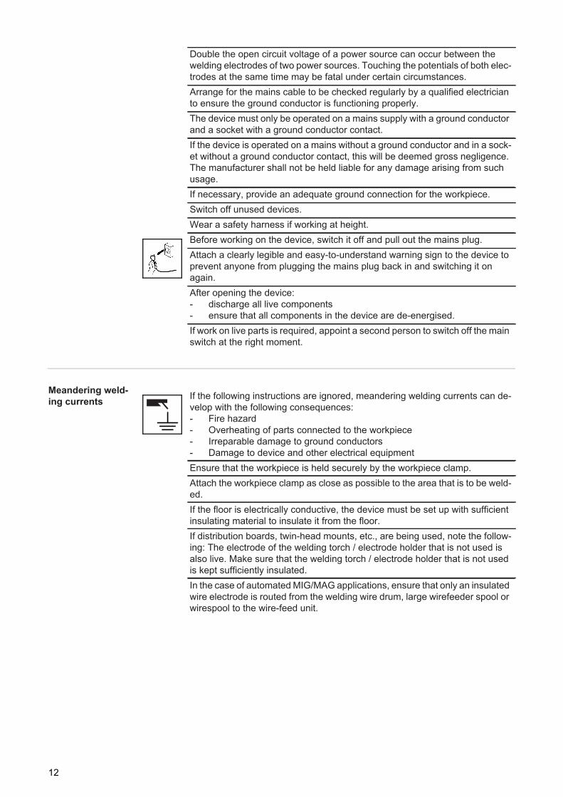
Meandering weld-ing currents
Double the open circuit voltage of a power source can occur between the welding electrodes of two power sources. Touching the potentials of both elec-trodes at the same time may be fatal under certain circumstances.Arrange for the mains cable to be checked regularly by a qualified electrician to ensure the ground conductor is functioning properly.The device must only be operated on a mains supply with a ground conductor and a socket with a ground conductor contact.If the device is operated on a mains without a ground conductor and in a sock-et without a ground conductor contact, this will be deemed gross negligence. The manufacturer shall not be held liable for any damage arising from such usage.If necessary, provide an adequate ground connection for the workpiece.Switch off unused devices.Wear a safety harness if working at height.Before working on the device, switch it off and pull out the mains plug.Attach a clearly legible and easy-to-understand warning sign to the device to prevent anyone from plugging the mains plug back in and switching it on again.After opening the device:- discharge all live components- ensure that all components in the device are de-energised.If work on live parts is required, appoint a second person to switch off the main switch at the right moment.
If the following instructions are ignored, meandering welding currents can de-velop with the following consequences:- Fire hazard- Overheating of parts connected to the workpiece- Irreparable damage to ground conductors- Damage to device and other electrical equipmentEnsure that the workpiece is held securely by the workpiece clamp.Attach the workpiece clamp as close as possible to the area that is to be weld-ed.If the floor is electrically conductive, the device must be set up with sufficient insulating material to insulate it from the floor.If distribution boards, twin-head mounts, etc., are being used, note the follow-ing: The electrode of the welding torch / electrode holder that is not used is also live. Make sure that the welding torch / electrode holder that is not used is kept sufficiently insulated.In the case of automated MIG/MAG applications, ensure that only an insulated wire electrode is routed from the welding wire drum, large wirefeeder spool or wirespool to the wire-feed unit.
12
EN
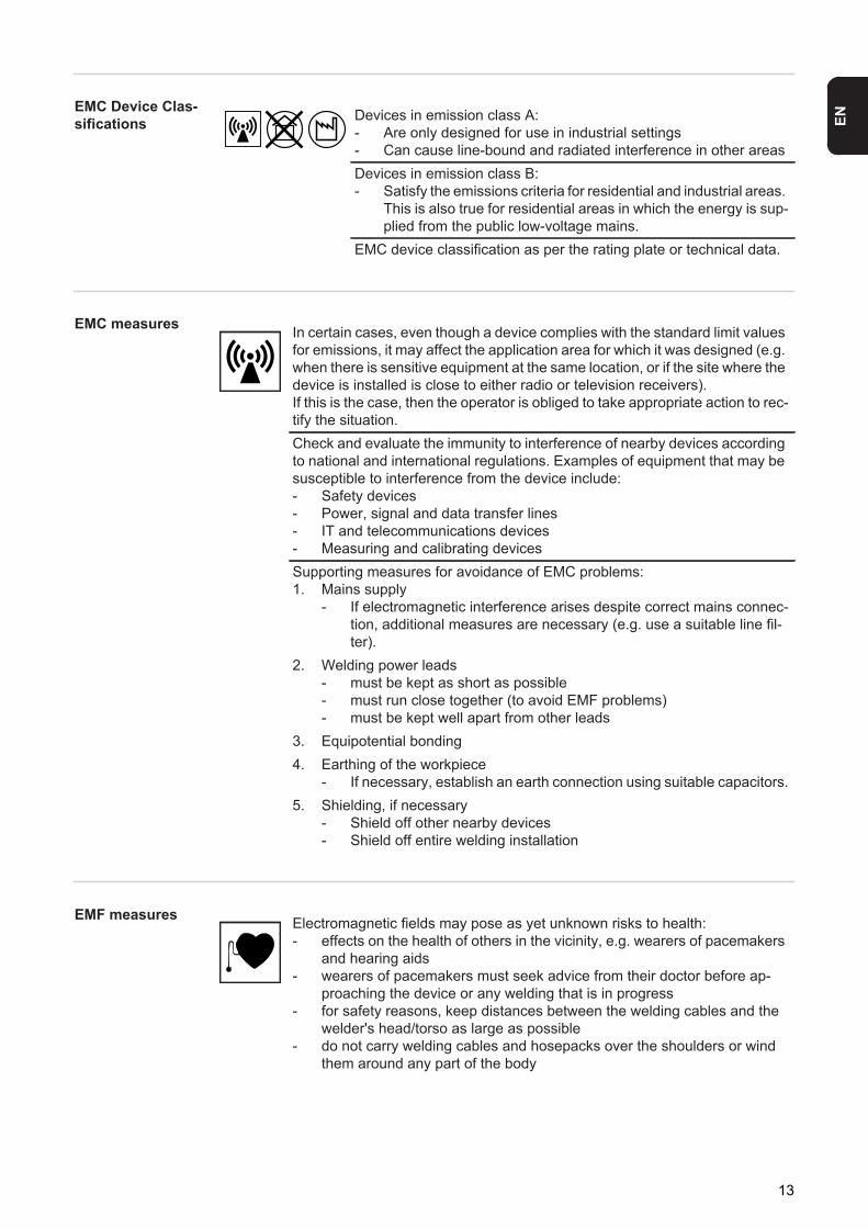
EMC Device Clas-sifications
EMC measures
EMF measures
Devices in emission class A:- Are only designed for use in industrial settings- Can cause line-bound and radiated interference in other areasDevices in emission class B:- Satisfy the emissions criteria for residential and industrial areas.
This is also true for residential areas in which the energy is sup-plied from the public low-voltage mains.
EMC device classification as per the rating plate or technical data.
In certain cases, even though a device complies with the standard limit values for emissions, it may affect the application area for which it was designed (e.g. when there is sensitive equipment at the same location, or if the site where the device is installed is close to either radio or television receivers).If this is the case, then the operator is obliged to take appropriate action to rec-tify the situation.Check and evaluate the immunity to interference of nearby devices according to national and international regulations. Examples of equipment that may be susceptible to interference from the device include:- Safety devices- Power, signal and data transfer lines- IT and telecommunications devices- Measuring and calibrating devicesSupporting measures for avoidance of EMC problems:1. Mains supply
- If electromagnetic interference arises despite correct mains connec-tion, additional measures are necessary (e.g. use a suitable line fil-ter).
2. Welding power leads- must be kept as short as possible- must run close together (to avoid EMF problems)- must be kept well apart from other leads
3. Equipotential bonding4. Earthing of the workpiece
- If necessary, establish an earth connection using suitable capacitors.5. Shielding, if necessary
- Shield off other nearby devices- Shield off entire welding installation
Electromagnetic fields may pose as yet unknown risks to health:- effects on the health of others in the vicinity, e.g. wearers of pacemakers
and hearing aids- wearers of pacemakers must seek advice from their doctor before ap-
proaching the device or any welding that is in progress- for safety reasons, keep distances between the welding cables and the
welder's head/torso as large as possible- do not carry welding cables and hosepacks over the shoulders or wind
them around any part of the body
13

Specific hazards Keep hands, hair, clothing and tools away from moving parts. For example:- Fans- Cogs- Rollers- Shafts- Wirespools and welding wiresDo not reach into the rotating cogs of the wire drive or into rotating drive com-ponents.Covers and side panels may only be opened/removed while maintenance or repair work is being carried out.During operation- Ensure that all covers are closed and all side panels are fitted properly.- Keep all covers and side panels closed.The welding wire emerging from the welding torch poses a high risk of injury (piercing of the hand, injuries to the face and eyes, etc.).
Therefore always keep the welding torch away from the body (devices with wire-feed unit) and wear suitable protective goggles.
Never touch the workpiece during or after welding - risk of burns.Slag can jump off cooling workpieces. The specified protective equipment must therefore also be worn when reworking workpieces, and steps must be taken to ensure that other people are also adequately protected.Welding torches and other parts with a high operating temperature must be al-lowed to cool down before handling.Special provisions apply in areas at risk of fire or explosion - observe relevant national and international regulations.
Power sources for work in areas with increased electric risk (e.g. near boilers) must carry the "Safety" sign. However, the power source must not be located in such areas.
Risk of scalding from escaping coolant. Switch off cooling unit before discon-necting coolant flow or return lines.
Observe the information on the coolant safety data sheet when handling cool-ant. The coolant safety data sheet may be obtained from your service centre or downloaded from the manufacturer's website.
Use only suitable load-carrying equipment supplied by the manufacturer when transporting devices by crane.- Hook chains and/or ropes onto all suspension points provided on the
load-carrying equipment.- Chains and ropes must be at the smallest angle possible to the vertical.- Remove gas cylinder and wire-feed unit (MIG/MAG and TIG devices).If the wire-feed unit is attached to a crane holder during welding, always use a suitable, insulated wirefeeder hoisting attachment (MIG/MAG and TIG de-vices).
14

EN
Factors affecting welding results
Danger from shielding gas cyl-inders
If the device has a carrying strap or handle, this is intended solely for carrying by hand. The carrying strap is not to be used if transporting with a crane, coun-terbalanced lift truck or other mechanical hoist.All lifting accessories (straps, handles, chains, etc.) used in connection with the device or its components must be tested regularly (e.g. for mechanical damage, corrosion or changes caused by other environmental factors).The testing interval and scope of testing must comply with applicable national standards and directives as a minimum.Odourless and colourless shielding gas may escape unnoticed if an adapter is used for the shielding gas connection. Prior to assembly, seal the device-side thread of the adapter for the shielding gas connection using suitable Tef-lon tape.
The following requirements with regard to shielding gas quality must be met if the welding system is to operate in a correct and safe manner:- Size of solid matter particles < 40 μm- Pressure dew point < -20 °C- Max. oil content < 25 mg/m³Filters must be used if necessary.
NOTE! There is an increased risk of soiling if ring mains are being used
Shielding gas cylinders contain gas under pressure and can explode if dam-aged. As the shielding gas cylinders are part of the welding equipment, they must be handled with the greatest of care.Protect shielding gas cylinders containing compressed gas from excessive heat, mechanical impact, slag, naked flames, sparks and arcs.Mount the shielding gas cylinders vertically and secure according to instruc-tions to prevent them falling over.Keep the shielding gas cylinders well away from any welding or other electrical circuits.Never hang a welding torch on a shielding gas cylinder.Never touch a shielding gas cylinder with an electrode.Risk of explosion - never attempt to weld a pressurised shielding gas cylinder.Only use shielding gas cylinders suitable for the application in hand, along with the correct and appropriate accessories (regulator, hoses and fittings). Only use shielding gas cylinders and accessories that are in good condition.Turn your face to one side when opening the valve of a shielding gas cylinder.Close the shielding gas cylinder valve if no welding is taking place.If the shielding gas cylinder is not connected, leave the valve cap in place on the cylinder.The manufacturer's instructions must be observed as well as applicable na-tional and international regulations for shielding gas cylinders and accesso-ries.
15
Safety measures at the installation location and dur-ing transport
Safety measures in normal opera-tion
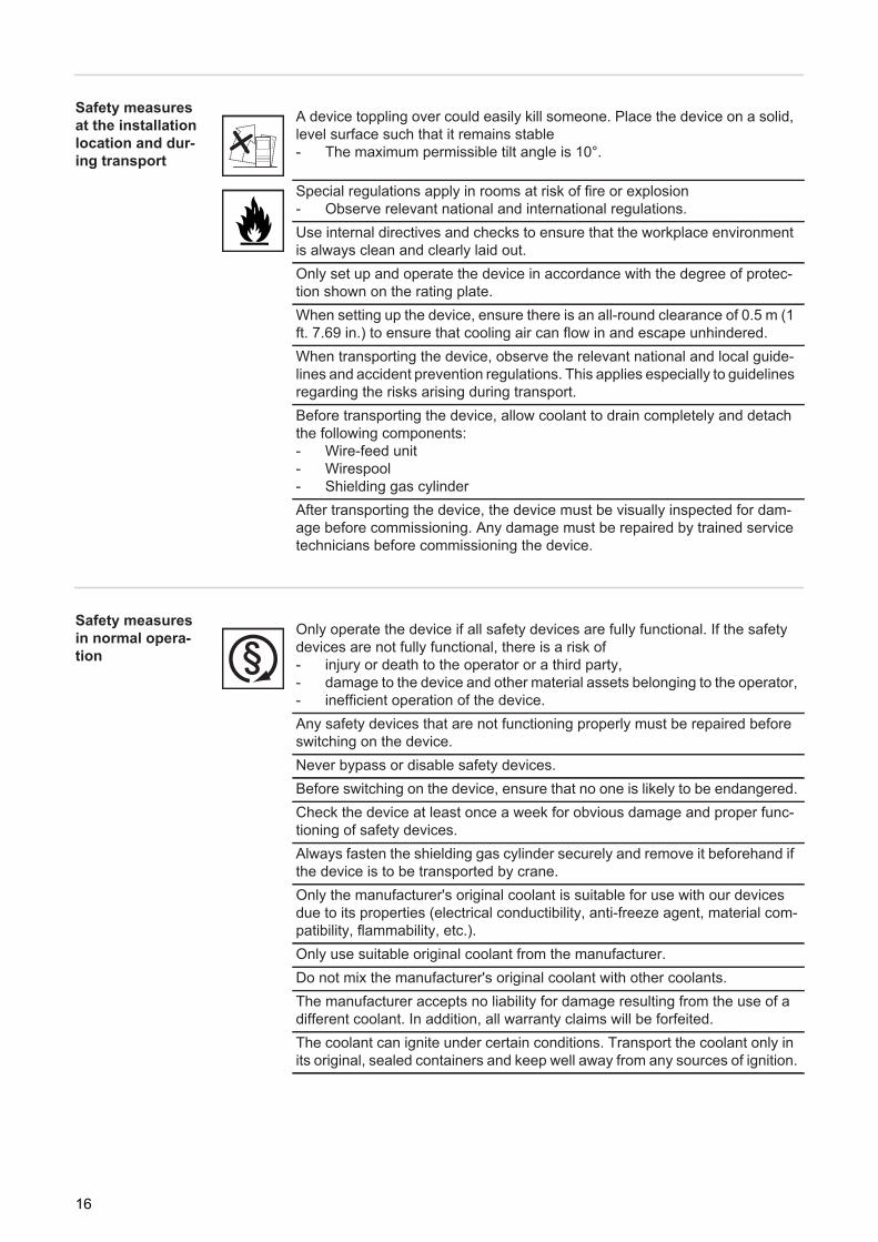
A device toppling over could easily kill someone. Place the device on a solid, level surface such that it remains stable- The maximum permissible tilt angle is 10°.
Special regulations apply in rooms at risk of fire or explosion- Observe relevant national and international regulations.Use internal directives and checks to ensure that the workplace environment is always clean and clearly laid out.Only set up and operate the device in accordance with the degree of protec-tion shown on the rating plate.When setting up the device, ensure there is an all-round clearance of 0.5 m (1 ft. 7.69 in.) to ensure that cooling air can flow in and escape unhindered.When transporting the device, observe the relevant national and local guide-lines and accident prevention regulations. This applies especially to guidelines regarding the risks arising during transport.Before transporting the device, allow coolant to drain completely and detach the following components:- Wire-feed unit- Wirespool- Shielding gas cylinderAfter transporting the device, the device must be visually inspected for dam-age before commissioning. Any damage must be repaired by trained service technicians before commissioning the device.
Only operate the device if all safety devices are fully functional. If the safety devices are not fully functional, there is a risk of- injury or death to the operator or a third party,- damage to the device and other material assets belonging to the operator,- inefficient operation of the device.Any safety devices that are not functioning properly must be repaired before switching on the device.Never bypass or disable safety devices.Before switching on the device, ensure that no one is likely to be endangered.Check the device at least once a week for obvious damage and proper func-tioning of safety devices.Always fasten the shielding gas cylinder securely and remove it beforehand if the device is to be transported by crane.Only the manufacturer's original coolant is suitable for use with our devices due to its properties (electrical conductibility, anti-freeze agent, material com-patibility, flammability, etc.).Only use suitable original coolant from the manufacturer.Do not mix the manufacturer's original coolant with other coolants.The manufacturer accepts no liability for damage resulting from the use of a different coolant. In addition, all warranty claims will be forfeited.The coolant can ignite under certain conditions. Transport the coolant only in its original, sealed containers and keep well away from any sources of ignition.
16

EN
Maintenance and repair
Safety inspection
Disposal
Safety symbols
Used coolant must be disposed of properly in accordance with the relevant na-tional and international regulations. The coolant safety data sheet may be ob-tained from your service centre or downloaded from the manufacturer's website.Check the coolant level before starting to weld, while the system is still cool.
It is impossible to guarantee that bought-in parts are designed and manufac-tured to meet the demands made of them, or that they satisfy safety require-ments. Use only original replacement and wearing parts (also applies to standard parts).Do not make any modifications, alterations, etc. to the device without the man-ufacturer's consent.Parts that are not in perfect condition must be replaced immediately.When ordering, please give the precise designation and part number as shown in the spare parts list, as well as the serial number of your device.
The manufacturer recommends that a safety inspection of the device is per-formed at least once every 12 months.The manufacturer recommends that the power source be calibrated during the same 12-month period.A safety inspection should be carried out by a qualified electrician- after any changes are made- after any additional parts are installed, or after any conversions- after repair, care and maintenance has been carried out- at least every twelve months.For safety inspections, follow the appropriate national and international stand-ards and directives.Further details on safety inspection and calibration can be obtained from your service centre. They will provide you on request with any documents you may require.
Do not dispose of this device with normal domestic waste! To comply with the European Directive 2002/96/EC on Waste Electrical and Electronic Equip-ment and its implementation as national law, electrical equipment that has reached the end of its life must be collected separately and returned to an ap-proved recycling facility. Any device that you no longer require must either be returned to your dealer or given to one of the approved collection and recycling facilities in your area. Ignoring this European Directive may have potentially adverse affects on the environment and your health!
Devices with the CE mark satisfy the essential requirements of the low-voltage and electromagnetic compatibility directive (e.g. relevant product norms from the EN 60 974 series).
Devices with the CSA test mark satisfy the requirements of the relevant stand-ards in Canada and the USA.
17

Data protection
Copyright
The user is responsible for the safekeeping of any changes made to the fac-tory settings. The manufacturer accepts no liability for any deleted personal settings.
Copyright of these operating instructions remains with the manufacturer.The text and illustrations are all technically correct at the time of printing. We reserve the right to make changes. The contents of the operating instructions shall not provide the basis for any claims whatsoever on the part of the pur-chaser. If you have any suggestions for improvement, or can point out any mistakes that you have found in the instructions, we will be most grateful for your comments.
18

General information


EN
General
Device concept The TPS 320i, TPS 400i and TPS 500i MIG/MAG power sources are completely digitised microprocessor-controlled inverter power sources.
The modular design and potential for sys-tem add-ons ensure a high degree of flexi-bility. The devices can be adapted to any specific situation.
Functional princi-ple
The central control and regulation unit of the power sources is coupled with a digital signal processor. The central control and regulation unit and the signal processor control the en-tire welding process.During the welding process, the actual data is measured continuously and the device re-sponds immediately to any changes. Control algorithms ensure that the desired target state is maintained.
This results in:- a precise welding process- exact reproducibility of all results- excellent weld properties.
Application areas The devices are used in workshops and industry for manual and automated applications with classical steel, galvanised sheets, chrome/nickel and aluminium.
The power sources are designed for:- Automobile and component supply industry- Machine manufacturing and rail vehicle construction- Chemical plant construction- Equipment construction- Shipyards, etc.
21
Warning notices on the device
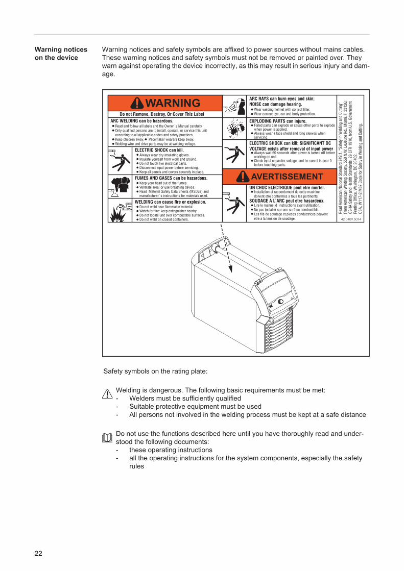
Warning notices and safety symbols are affixed to power sources without mains cables. These warning notices and safety symbols must not be removed or painted over. They warn against operating the device incorrectly, as this may result in serious injury and dam-age.
Safety symbols on the rating plate:
Welding is dangerous. The following basic requirements must be met:- Welders must be sufficiently qualified- Suitable protective equipment must be used- All persons not involved in the welding process must be kept at a safe distance
Do not use the functions described here until you have thoroughly read and under-stood the following documents:- these operating instructions- all the operating instructions for the system components, especially the safety
rules
22
EN
Welding processes, processes and welding charac-teristics
General TPSi power sources contain a selection of welding processes, procedures and welding characteristics that enable a wide range of materials to be processed in the most effective way.
Welding charac-teristics
Summary of MIG/MAG pulse weld-ing
MIG/MAG pulse synergic
MIG/MAG pulse welding is a pulsed-arc process with controlled material transfer. In the base current phase, the energy supply is reduced to such an extent that the arc is only just stable and the surface of the workpiece is preheated. In the pulsing current phase, a precise current pulse ensures the targeted detachment of a droplet of welding material.This principle guarantees a low-spatter weld and precise working in the lower power range, as unwelcome short circuits with simultaneous droplet explosion and uncontrolled welding spatter are virtually eliminated.
Summary of MIG/MAG standard synergic welding
MIG/MAG standard synergic
The MIG/MAG standard synergic welding process is a MIG/MAG welding process across the entire power range of the power source with the following arc types:
Short circuit arcDroplet transfer takes place during a short circuit in the lower power range.
Intermediate arcThe droplet increases in size on the end of the wire electrode and is transferred in the mid-power range during the short circuit.
Spray arcA short circuit-free transfer of material in the high power range.
Depending on the material and shielding gas mix, various process-optimised welding characteristics are available when selecting the filler metal.The additional marking next to the material provides information about the use of the welding characteristic:
Universal Characteristic for conventional welding tasks
Dynamic Characteristic for high welding speeds with concentrated arc
Root Characteristic for root passes with powerful arc
PCS Pulse Controlled Sprayarc
Direct transition from the concentrated pulse to a short spray arc. The advantages of pulse and standard arcs combined in a single charac-teristic.
23
Summary of the PMC process
PMC = Pulse Multi Control
PMC is a pulsed arc welding process with high-speed data processing, precise recording of the process status and improved droplet detachment. Faster welding possible with a sta-ble arc and even fusion penetration.
Summary of the LSC / LSC Ad-vanced process
LSC = Low Spatter Control
LSC is a new, low-spatter dip transfer arc process.The current is reduced before breaking the short-circuit bridge; re-ignition takes place at significantly lower welding current values.
LSC AdvancedThe TPS 400i LSC ADV is required for the LSC Advanced process. The TPS 400i LSC ADV accelerates the reduction in current and improves the LSC prop-erties. The LSC Advanced process is predominantly used when the welding circuit induc-tivity is higher.
Summary of the CMT process
CMT = Cold Metal Transfer
The CMT process is a special MIG/MAG dip transfer arc welding process. In the CMT process, the digital process control system detects a short circuit and facilitates droplet detachment by retracting the wire electrode. The wire electrode can be retracted more than 100 times per second. The special features of the CMT process include low heat input and a controlled, low-cur-rent material transfer.
The CMT process is suitable for:- virtually spatter-free MIG brazing- welding on light-gauge sheet with minimal distortion- joining steel and aluminium (weld brazing)
24
EN
System components
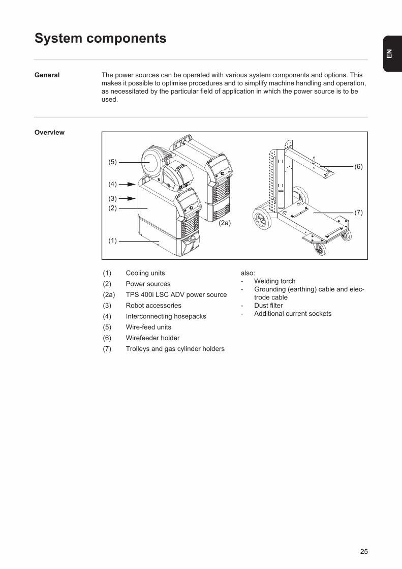
General The power sources can be operated with various system components and options. This makes it possible to optimise procedures and to simplify machine handling and operation, as necessitated by the particular field of application in which the power source is to be used.
Overview
(1) Cooling units also:- Welding torch- Grounding (earthing) cable and elec-
trode cable- Dust filter- Additional current sockets
(2) Power sources(2a) TPS 400i LSC ADV power source(3) Robot accessories(4) Interconnecting hosepacks(5) Wire-feed units(6) Wirefeeder holder(7) Trolleys and gas cylinder holders
(1)
(2)(3)
(4)
(5)(6)
(7)(2a)
25

26

Controls, connections and mechani-cal components

EN
Control panel
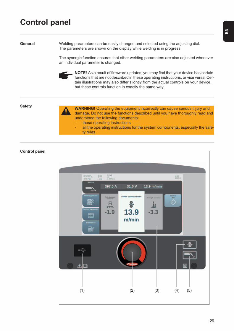
General Welding parameters can be easily changed and selected using the adjusting dial. The parameters are shown on the display while welding is in progress.
The synergic function ensures that other welding parameters are also adjusted whenever an individual parameter is changed.
Safety
Control panel
NOTE! As a result of firmware updates, you may find that your device has certain functions that are not described in these operating instructions, or vice versa. Cer-tain illustrations may also differ slightly from the actual controls on your device, but these controls function in exactly the same way.
WARNING! Operating the equipment incorrectly can cause serious injury and damage. Do not use the functions described until you have thoroughly read and understood the following documents:- these operating instructions- all the operating instructions for the system components, especially the safe-
ty rules
(1) (2) (3) (4) (5)
AlMg 5
29
No. Function(1) USB port
For connecting USB sticks, hard drives without their own power supply, etc.
IMPORTANT: The USB port is not electrically isolated from the welding circuit. Therefore, devices that establish an electrical connection with another device must not be connected to the USB port.
(2) Adjusting dial with turn/press function for selecting elements, setting values and scrolling through lists.
(3) Display (touchscreen)- to directly operate the power source by pressing the buttons on the display- to show values- to navigate in the menu
(4) Wire threading button for threading the wire electrode into the torch hosepack with no accompanying flow of gas or current
(5) Gas test button for setting the required gas flow rate on the gas pressure regulator.After pressing this button, gas flows for 30 seconds. Press the button again to stop the gas test flow before the end of this period.
30

EN
Connections, switches and mechanical components
TPS 320i / 400i / 500i power source, TPS 400i LSC ADV power source
Front Rear
(1)
(2) (3)
(4)
(6)
(5)
(7)
(8)(12)(13)
(9)
(10)
(11)
No. Function(1) Mains switch
for switching the power source on and off(2) Control panel cover
for protecting the control panel(3) Control panel with display
for operating the power source(4) (-) current socket with bayonet latch
for:- connecting the grounding (earthing) cable during MIG/MAG welding
(5) Blanking cover reserved for second (+) current socket with bayonet latch
(6) Blanking cover reserved for second SpeedNet connection socket option
(7) Blanking cover reserved for second SpeedNet connection socket option
(8) (+) current socket with bayonet latch for:- connecting the current cable from the interconnecting hosepack during MIG/
MAG welding(9) SpeedNet connection socket
for connecting the interconnecting hosepack(10) Ethernet port(11) Mains cable with strain relief device(12) Blanking cover
reserved for second (-) current socket option with bayonet latch
The second (-) current socket is for:- connecting the interconnecting hosepack during MIG/MAG welding for polar-
ity reversal (e.g. for flux-cored wire welding)(13) Blanking cover
reserved for second SpeedNet connection socket option or robot interface RI FB Inside/i
31

32

Operating concept

EN
Input options
General
The following input options are available on the power source control panel:- Turning/pressing the adjusting dial- Pressing buttons- Pressing on the display
Turning/pressing the adjusting dial
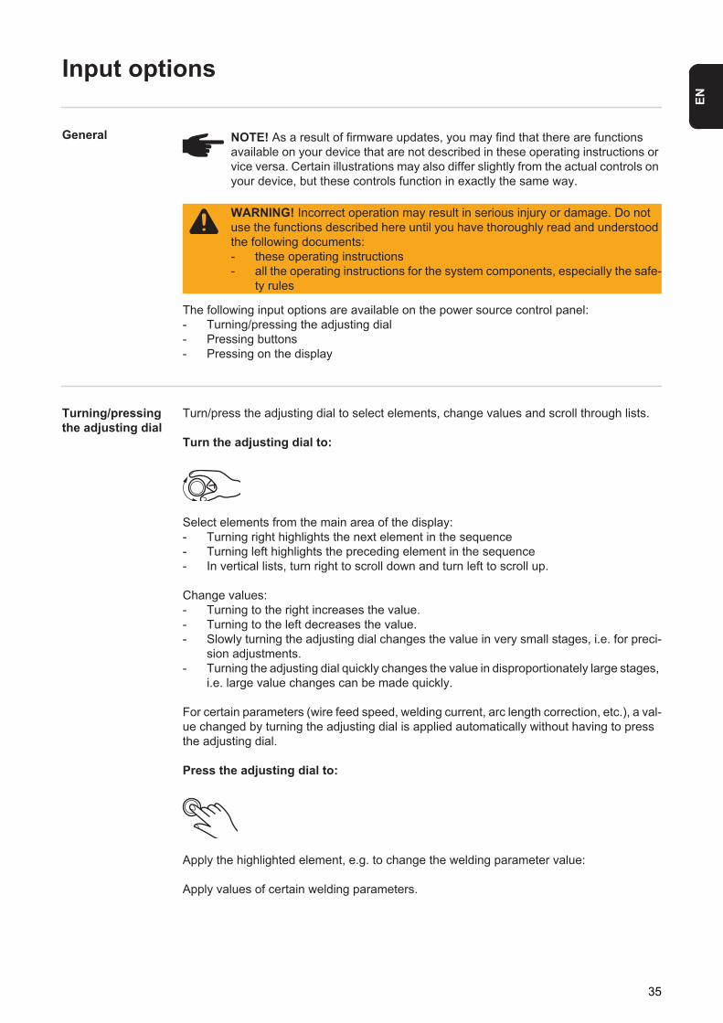
Turn/press the adjusting dial to select elements, change values and scroll through lists.
Turn the adjusting dial to:
Select elements from the main area of the display:- Turning right highlights the next element in the sequence- Turning left highlights the preceding element in the sequence- In vertical lists, turn right to scroll down and turn left to scroll up.
Change values:- Turning to the right increases the value.- Turning to the left decreases the value.- Slowly turning the adjusting dial changes the value in very small stages, i.e. for preci-
sion adjustments.- Turning the adjusting dial quickly changes the value in disproportionately large stages,
i.e. large value changes can be made quickly.
For certain parameters (wire feed speed, welding current, arc length correction, etc.), a val-ue changed by turning the adjusting dial is applied automatically without having to press the adjusting dial.
Press the adjusting dial to:
Apply the highlighted element, e.g. to change the welding parameter value:
Apply values of certain welding parameters.
NOTE! As a result of firmware updates, you may find that there are functions available on your device that are not described in these operating instructions or vice versa. Certain illustrations may also differ slightly from the actual controls on your device, but these controls function in exactly the same way.
WARNING! Incorrect operation may result in serious injury or damage. Do not use the functions described here until you have thoroughly read and understood the following documents:- these operating instructions- all the operating instructions for the system components, especially the safe-
ty rules
35

Pressing buttons
Pressing on the display
Pressing on (and therefore selecting) an element on the display highlights this element.
Pressing buttons triggers the following functions:
When the feeder inching button is pressed, the wire electrode is fed into the torch hosepack with no accompanying flow of gas or current.
When the gas test button is pressed, gas will flow out for 30 seconds. Press the button again to stop the gas test flow before the end of this period.
The display can be touched in order to- navigate,- trigger functions,- select options
36
EN
Display and status line
Display
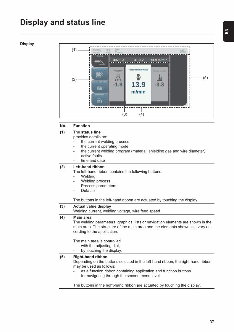
No. Function(1) The status line
provides details on:- the current welding process- the current operating mode- the current welding program (material, shielding gas and wire diameter)- active faults- time and date
(2) Left-hand ribbonThe left-hand ribbon contains the following buttons:- Welding- Welding process- Process parameters- Defaults
The buttons in the left-hand ribbon are actuated by touching the display.(3) Actual value display
Welding current, welding voltage, wire feed speed(4) Main area
The welding parameters, graphics, lists or navigation elements are shown in the main area. The structure of the main area and the elements shown in it vary ac-cording to the application.
The main area is controlled- with the adjusting dial,- by touching the display.
(5) Right-hand ribbonDepending on the buttons selected in the left-hand ribbon, the right-hand ribbon may be used as follows:- as a function ribbon containing application and function buttons- for navigating through the second menu level
The buttons in the right-hand ribbon are actuated by touching the display.
(1)
(2)
(4)
(5)
(3)
AlMg 5
37
Status line
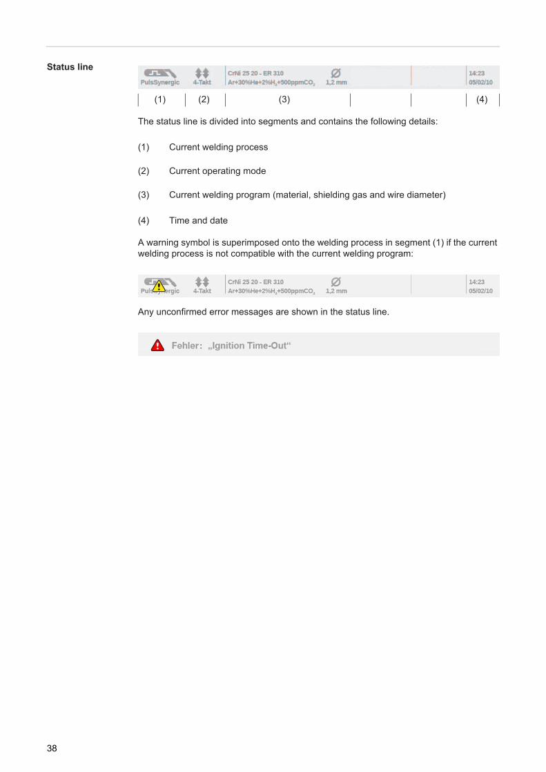
The status line is divided into segments and contains the following details:
(1) Current welding process
(2) Current operating mode
(3) Current welding program (material, shielding gas and wire diameter)
(4) Time and date
A warning symbol is superimposed onto the welding process in segment (1) if the current welding process is not compatible with the current welding program:
Any unconfirmed error messages are shown in the status line.
(1) (2) (3) (4) * (5) (4)
38

Installation and commissioning


EN
Minimum equipment needed for welding task
General Depending on which welding process you intend to use, a certain minimum equipment lev-el will be needed in order to work with the power source. The welding processes and the minimum equipment levels required for the welding task are then described.
MIG/MAG gas-cooled welding
- Power source- Grounding (earthing) cable- MIG/MAG welding torch, gas-cooled- Shielding gas supply- Wire-feed unit- Interconnecting hosepack- Wire electrode
MIG/MAG water-cooled welding
- Power source- Cooling unit- Grounding (earthing) cable- MIG/MAG welding torch, water-cooled- Shielding gas supply- Wire-feed unit- Interconnecting hosepack- Wire electrode
41
Before installation and commissioning
Safety
Proper use The power source is designed to be used for MIG/MAG welding. Any use above and be-yond this purpose is deemed improper. The manufacturer shall not be held liable for any damage arising from such usage.
Proper use includes:- complying with all the operating instructions- performing all stipulated inspection and maintenance work
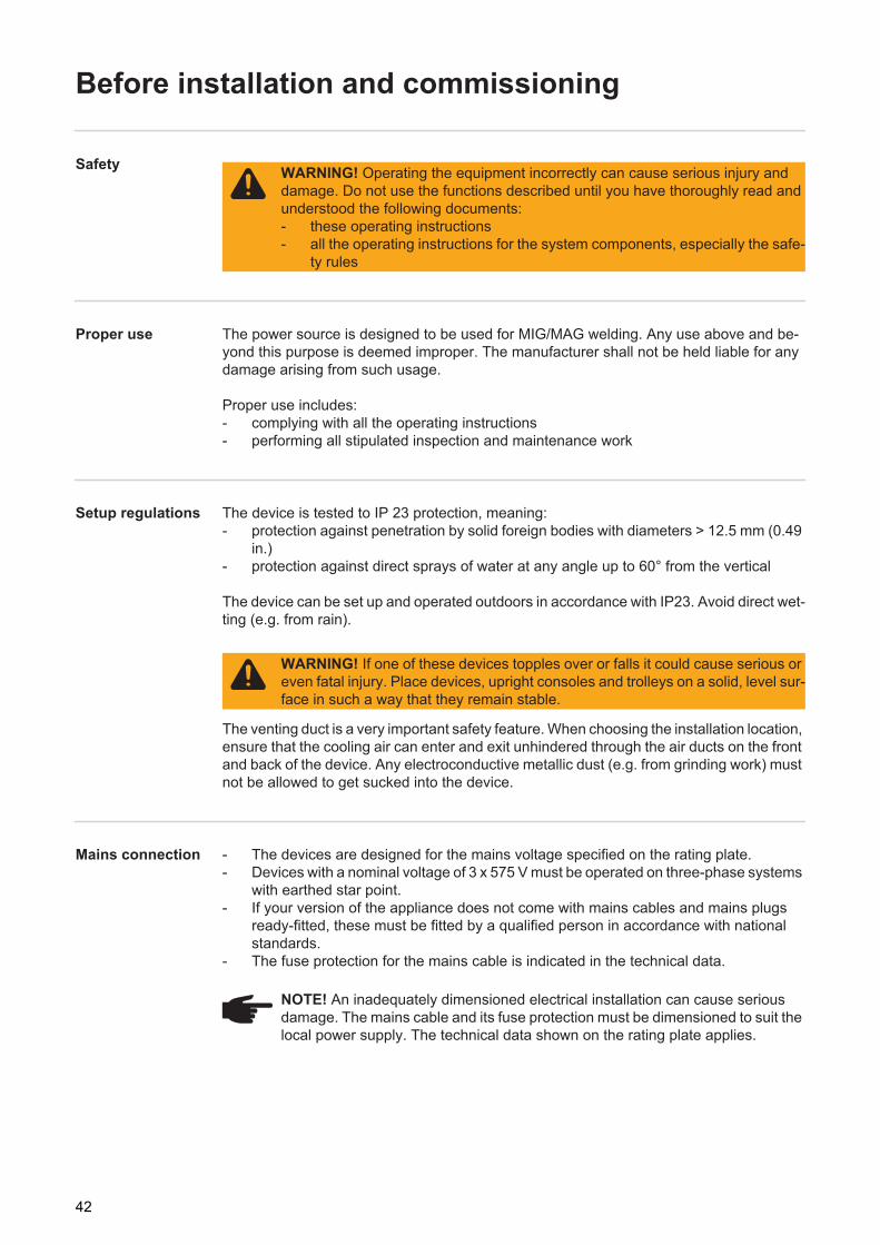
Setup regulations The device is tested to IP 23 protection, meaning:- protection against penetration by solid foreign bodies with diameters > 12.5 mm (0.49
in.)- protection against direct sprays of water at any angle up to 60° from the vertical
The device can be set up and operated outdoors in accordance with IP23. Avoid direct wet-ting (e.g. from rain).
The venting duct is a very important safety feature. When choosing the installation location, ensure that the cooling air can enter and exit unhindered through the air ducts on the front and back of the device. Any electroconductive metallic dust (e.g. from grinding work) must not be allowed to get sucked into the device.
Mains connection - The devices are designed for the mains voltage specified on the rating plate.- Devices with a nominal voltage of 3 x 575 V must be operated on three-phase systems
with earthed star point.- If your version of the appliance does not come with mains cables and mains plugs
ready-fitted, these must be fitted by a qualified person in accordance with national standards.
- The fuse protection for the mains cable is indicated in the technical data.
WARNING! Operating the equipment incorrectly can cause serious injury and damage. Do not use the functions described until you have thoroughly read and understood the following documents:- these operating instructions- all the operating instructions for the system components, especially the safe-
ty rules
WARNING! If one of these devices topples over or falls it could cause serious or even fatal injury. Place devices, upright consoles and trolleys on a solid, level sur-face in such a way that they remain stable.
NOTE! An inadequately dimensioned electrical installation can cause serious damage. The mains cable and its fuse protection must be dimensioned to suit the local power supply. The technical data shown on the rating plate applies.
42

EN
Generator-pow-ered operation
The power source is generator-compatible.
The maximum apparent power S1max of the power source must be known in order to select the correct generator output. The maximum apparent power S1max of the power source is calculated as follows:
The generator apparent power SGEN needed is calculated using the following rule of thumb:
A smaller generator may be used when not welding at full power.
IMPORTANT! The generator apparent power SGEN must always be higher than the maxi-mum apparent power S1max of the power source.
When using single-phase devices with a 3-phase generator, note that the specified gener-ator apparent power is often only available as a whole across all three phases of the gen-erator. If necessary, obtain further information on the single-phase power of the generator from the generator manufacturer.
Information on system compo-nents
The steps and activities described below include references to various system compo-nents, including:- Trolleys- Cooling units- Wire-feed unit holders- Wire-feed units- Interconnecting hosepacks- Welding torches- etc.
For more detailed information about installing and connecting the system components, please refer to the appropriate operating instructions.
3-phase devices:
S1max = I1max x U1 x √3
Single-phase devices:
S1max = I1max x U1
See device rating plate or technical data for I1max and U1 values
SGEN = S1max x 1.35
NOTE! The voltage delivered by the generator must never exceed the upper or lower limits of the mains voltage tolerance range. Details of the mains voltage tol-erance can be found in the "Technical data" section.
43
Connecting the mains cable
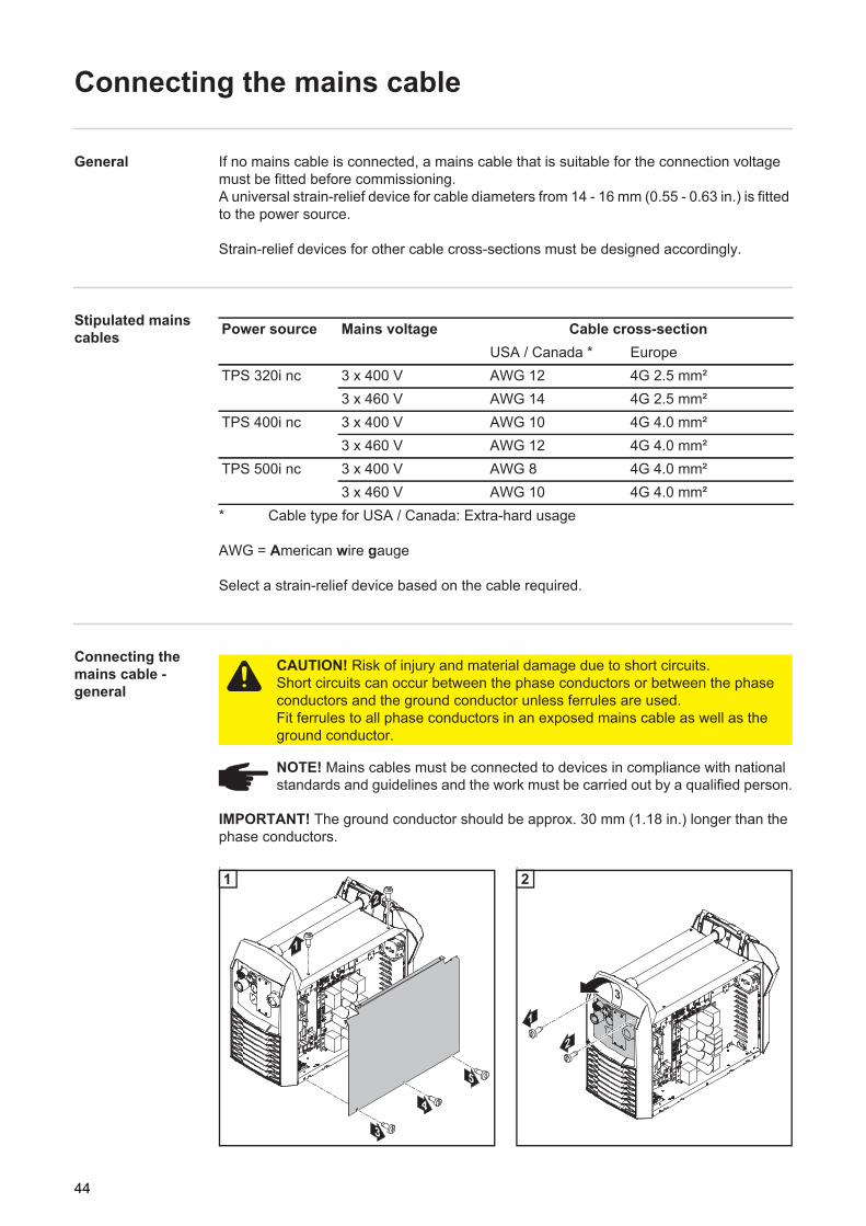
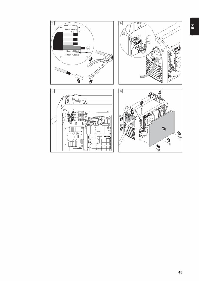
General If no mains cable is connected, a mains cable that is suitable for the connection voltage must be fitted before commissioning. A universal strain-relief device for cable diameters from 14 - 16 mm (0.55 - 0.63 in.) is fitted to the power source.
Strain-relief devices for other cable cross-sections must be designed accordingly.
Stipulated mains cables
* Cable type for USA / Canada: Extra-hard usage
AWG = American wire gauge
Select a strain-relief device based on the cable required.
Connecting the mains cable - general
IMPORTANT! The ground conductor should be approx. 30 mm (1.18 in.) longer than the phase conductors.
1 2
Power source Mains voltage Cable cross-sectionUSA / Canada * Europe
TPS 320i nc 3 x 400 V AWG 12 4G 2.5 mm²3 x 460 V AWG 14 4G 2.5 mm²
TPS 400i nc 3 x 400 V AWG 10 4G 4.0 mm²3 x 460 V AWG 12 4G 4.0 mm²
TPS 500i nc 3 x 400 V AWG 8 4G 4.0 mm²3 x 460 V AWG 10 4G 4.0 mm²
CAUTION! Risk of injury and material damage due to short circuits. Short circuits can occur between the phase conductors or between the phase conductors and the ground conductor unless ferrules are used. Fit ferrules to all phase conductors in an exposed mains cable as well as the ground conductor.
NOTE! Mains cables must be connected to devices in compliance with national standards and guidelines and the work must be carried out by a qualified person.
1 2
44
EN
3 4
5 6
3 4
5
3 4
5
9
8
7
6
2
6
45

Commissioning the TPS 320i / 400i / 500i, TPS 400i LSC ADV
Safety
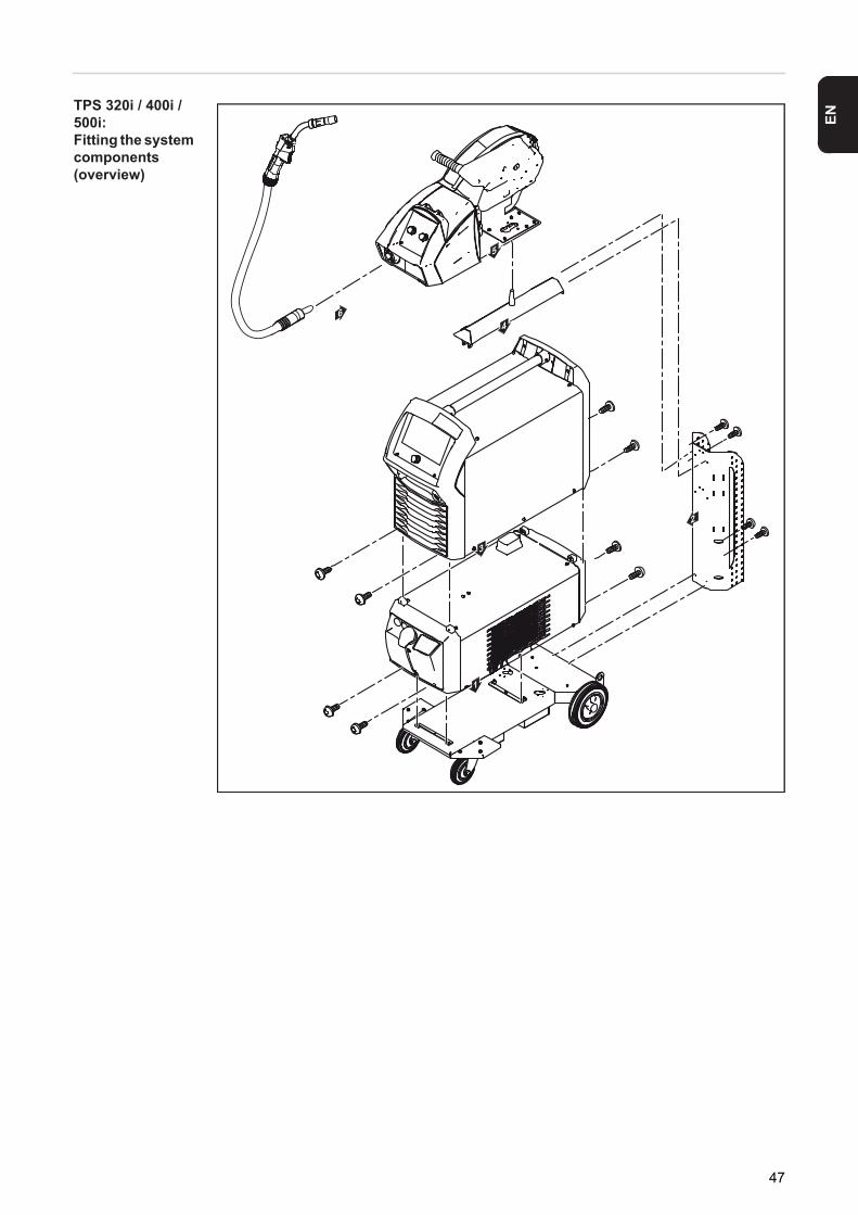
General A manual water-cooled MIG/MAG application is used to describe how to commission the TPS 320i / 400i / 500i and TPS 400i LSC ADV power sources.
The following illustrations provide an overview of the structure of the individual system components.Refer to the respective system component operating instructions for detailed information about the various work steps involved.
WARNING! An electric shock can be fatal. If the power source is connected to the mains electricity supply during installation, there is a high risk of very serious in-jury and damage. Before carrying out any work on the device make sure that:- the power source mains switch is in the "O" position- the power source is unplugged from the mains
46
EN
TPS 320i / 400i / 500i: Fitting the system components (overview)
1
6
2
3
4
5
47

TPS 400i LSC ADV: Fitting the system components (overview)
48

EN
Fixing the strain-relief device for the interconnect-ing hosepack
1
Fixing the strain-relief device to the trolley
2
Fixing the strain-relief device to the wire-feed unit
Connecting the interconnecting hosepack
1
Connecting the interconnecting hosepack to the power source and cooling unit
2
Connecting the interconnecting hosepack to the wire-feed unit
* (only if coolant connections are installed in the wire-feed unit and a water-cooled interconnecting hose-pack is being used)
1
2
34
1
2
1
34
2
NOTE! There is no cooling unit present in the case of gas-cooled systems. There is no need to attach the water connections in the case of gas-cooled systems.
1 2
49
Connecting the gas cylinder
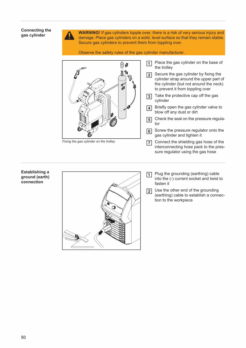
Fixing the gas cylinder on the trolley
Place the gas cylinder on the base of the trolleySecure the gas cylinder by fixing the cylinder strap around the upper part of the cylinder (but not around the neck) to prevent it from toppling overTake the protective cap off the gas cylinderBriefly open the gas cylinder valve to blow off any dust or dirtCheck the seal on the pressure regula-torScrew the pressure regulator onto the gas cylinder and tighten itConnect the shielding gas hose of the interconnecting hose pack to the pres-sure regulator using the gas hose
Establishing a ground (earth) connection
Plug the grounding (earthing) cable into the (-) current socket and twist to fasten itUse the other end of the grounding (earthing) cable to establish a connec-tion to the workpiece
WARNING! If gas cylinders topple over, there is a risk of very serious injury and damage. Place gas cylinders on a solid, level surface so that they remain stable. Secure gas cylinders to prevent them from toppling over.
Observe the safety rules of the gas cylinder manufacturer.
6
7
72
1
3 1
2
3
4
5
6
7
2
1
1
2
50

EN
Connecting MIG/MAG welding torches to the wire-feed unit
Check that all cables, leads and hose-packs are undamaged and correctly in-sulatedOpen the wire drive coverOpen the clamping lever on the wire drive
Check that the welding torch is correc-tly and completely tooled up. Insert it - marking at the top first - into the wel-ding torch connection on the wire-feed unitClose the clamping lever on the wire drive
Connect the coolant flow hose to the coolant flow connection (blue)Connect the coolant return hose to the coolant return connection (red)
Close the wire drive coverCheck that all connections are connec-ted properly
3
2
1
23
4
76
*5
* On water-cooled welding torches:
4
5
6
7
8
89
51

Other tasks Carry out the following steps in accordance with the wire-feed unit operating instructions:Insert the feed rollers in the wire-feed unitInsert the wirespool or basket-type spool with adapter in the wire-feed unitFeed in the wire electrodeSet the contact pressureAdjust the brake
12345
52

Welding

EN
MIG/MAG modes
General
See the Setup menu for information on settings, setting range and units of measurement for the available parameters.
Symbols and their explanations
A detailed explanation of the parameters can be found in the section headed "Process pa-rameters"
WARNING! Operating the equipment incorrectly can cause serious injury and damage. Do not use the functions described until you have thoroughly read and understood the following documents:- these operating instructions- all the operating instructions for the system components, especially the safe-
ty rules
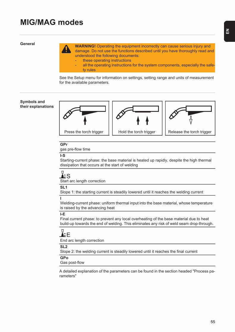
Press the torch trigger Hold the torch trigger Release the torch trigger
GPrgas pre-flow timeI-SStarting-current phase: the base material is heated up rapidly, despite the high thermal dissipation that occurs at the start of welding
Start arc length correctionSL1Slope 1: the starting current is steadily lowered until it reaches the welding currentIWelding-current phase: uniform thermal input into the base material, whose temperature is raised by the advancing heatI-EFinal current phase: to prevent any local overheating of the base material due to heat build-up towards the end of welding. This eliminates any risk of weld seam drop-through.
End arc length correctionSL2Slope 2: the welding current is steadily lowered until it reaches the final currentGPoGas post-flow
S
E
55
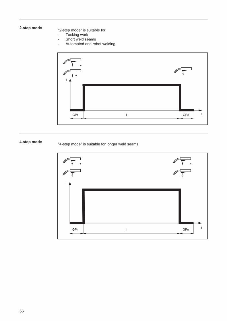
2-step mode
4-step mode
“2-step mode“ is suitable for- Tacking work- Short weld seams- Automated and robot welding
t
I
+
IGPr GPo
"4-step mode" is suitable for longer weld seams.
t
I
+
IGPr GPo
+
56

EN
Special 4-step mode "Special 4-step mode" is particularly suitable for welding aluminium materials. The spe-
cial slope of the welding current curve takes account of the high thermal conductivity of aluminium.
I
tIGPr GPoE-I L1SS-I SL2
+ +
S
E
57
MIG/MAG welding
Safety
MIG/MAG welding - overview
The "MIG/MAG welding" section comprises the following steps:- Switching on the power source- Selecting the welding process and operating mode- Selecting the filler metal- Setting the welding and process parameters- Setting the shielding gas flow rate- MIG/MAG welding
Switch on the power source
Insert the mains cableMove the mains switch to the I position
A cooling unit connected to the system will begin to operate.
For the best welding results, Fronius recommends that an R/L adjustment is carried out every time the device is switched on.More information about the R/L adjustment can be found under "R/L adjustment" in the "Process parameters" section of this chapter.
WARNING! Operating the equipment incorrectly can cause serious injury and damage. Do not use the functions described until you have thoroughly read and understood the following documents:- these operating instructions- all the operating instructions for the system components, especially the safe-
ty rules
WARNING! An electric shock can be fatal. If the power source is connected to the mains electricity supply during installation, there is a high risk of very serious in-jury and damage. Before carrying out any work on the device make sure that:- the power source mains switch is in the "O" position- the power source is unplugged from the mains
NOTE! If using a cooling unit, follow the safety rules and note the operating con-ditions in the cooling unit operating instructions.
12
58

EN
Setting the weld-ing process and operating mode
Setting the welding process
Select the "Welding process" button in the left-hand ribbonSelect the "Process" button in the right-hand ribbon
An overview of the welding processes is displayed:- MIG/MAG pulse synergic welding- MIG/MAG standard synergic welding
Select the desired welding process
Setting the operating mode
Select the "Operating mode" button in the right-hand ribbon
2
3
1
12
3
5
4
AlMg 5
4
59

An overview of the operating modes is displayed.- 2-step mode- 4-step mode- Special 4-step mode
Select the desired operating mode
Selecting the filler metal
Select the "Welding process" button in the left-hand ribbonSelect the "Filler metal" button in the right-hand ribbon.
An overview of the filler metals is displayed.
Press the "Change material settings" button
The first step of the filler metal wizard is displayed:
5
1
2
3
AlMg 5
AlMg 5
12
3
60

EN
Select the desired filler metal by turning the adjusting dialPress "Next" (or press the adjusting dial)
The next step of the filler metal wizard is displayed:
Select the desired wire diameter by turning the adjusting dialPress "Next" (or press the adjusting dial)
The next step of the filler metal wizard is displayed:
4
5
5
AlMg 5
AlMg 5
AlSi 5
45
6
7
7
AlMg 5
AlMg 5
67
61
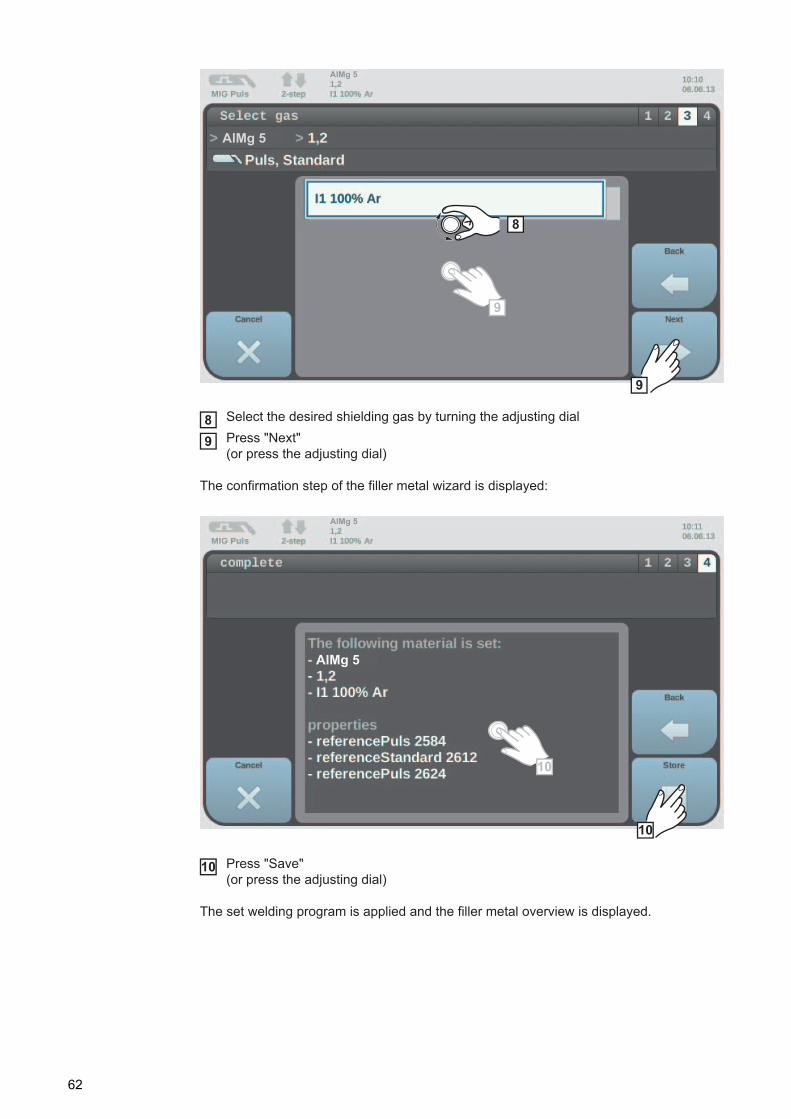
Select the desired shielding gas by turning the adjusting dialPress "Next" (or press the adjusting dial)
The confirmation step of the filler metal wizard is displayed:
Press "Save" (or press the adjusting dial)
The set welding program is applied and the filler metal overview is displayed.
8
9
9
AlMg 5
AlMg 5
89
10
10
AlMg 5
AlMg 5
10
62

EN
Setting the weld-ing parameters
Select the "Welding" button in the left-hand ribbonSelect the desired welding parameter by turning the adjusting dialPress the adjusting dial to change the parameter
The value of the parameter is displayed as a horizontal scale:
e.g. on the wire-feed unit
The value of the selected parameter can now be changed.
Turn the adjusting dial to change the parameter
The adjusted value of the parameter is applied immediately. If one of the parameters feeder command value, sheet thickness, welding current or weld-ing voltage is changed during synergic welding, the other parameters are immediately ad-justed accordingly.
Press the adjusting dial to call up the welding parameters overviewAdjust the process parameters accordingly to make user- or application-specific set-tings on the welding device
1
2
3
AlMg 5
123
4
4
56
63

Setting the shielding gas flow rate
Open the gas cylinder valvePress the gas test button
Shielding gas flows out
Turn the adjusting screw on the underside of the pressure regulator until the pressure gauge shows the required shielding gas flow ratePress the gas test button
The flow of gas stops.
MIG/MAG welding
Select the "Welding" button in the left-hand ribbon
Press the torch trigger and start welding
Whenever welding ends, the actual values for welding current, welding voltage and wire feed speed are stored, and HOLD appears on the display.
12
3
4
CAUTION! Risk of injury and damage from electric shock and from the wire elec-trode emerging from the torch. When pressing the torch trigger:- keep the torch away from your face and body- do not point the welding torch at people- make sure that the wire electrode does not touch any electrically conducting
or earthed (grounded) parts, such as the housing, etc.
NOTE! Parameters that have been set on a system component control panel (e.g. wire feed unit or remote control) might not be able to be changed on the pow-er source control panel.
1
AlMg 5
1
2
64

EN
EasyJob mode
General If EasyJob mode has been activated, 5 additional buttons appear on the display. These enable up to 5 operating points to be saved at the touch of a button.The current welding settings are saved.
Activating Easy-Job mode
Select the "Defaults" button in the left-hand ribbonSelect the "EasyJobs" button
The overview to activate / deactivate EasyJob mode is displayed.
Select the "EasyJobs on" button
2
1
12
3
4
3
65
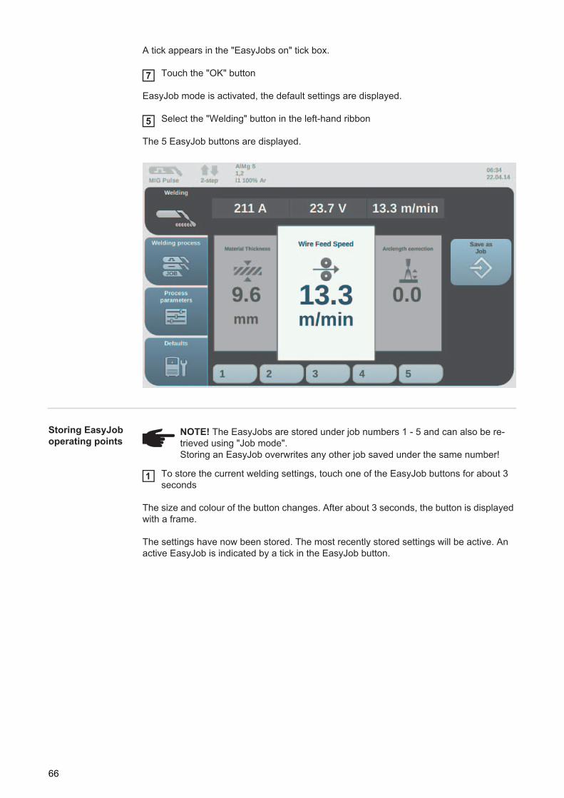
A tick appears in the "EasyJobs on" tick box.
Touch the "OK" button
EasyJob mode is activated, the default settings are displayed.
Select the "Welding" button in the left-hand ribbon
The 5 EasyJob buttons are displayed.
Storing EasyJob operating points
To store the current welding settings, touch one of the EasyJob buttons for about 3 seconds
The size and colour of the button changes. After about 3 seconds, the button is displayed with a frame.
The settings have now been stored. The most recently stored settings will be active. An active EasyJob is indicated by a tick in the EasyJob button.
7
5
NOTE! The EasyJobs are stored under job numbers 1 - 5 and can also be re-trieved using "Job mode".Storing an EasyJob overwrites any other job saved under the same number!
1
66
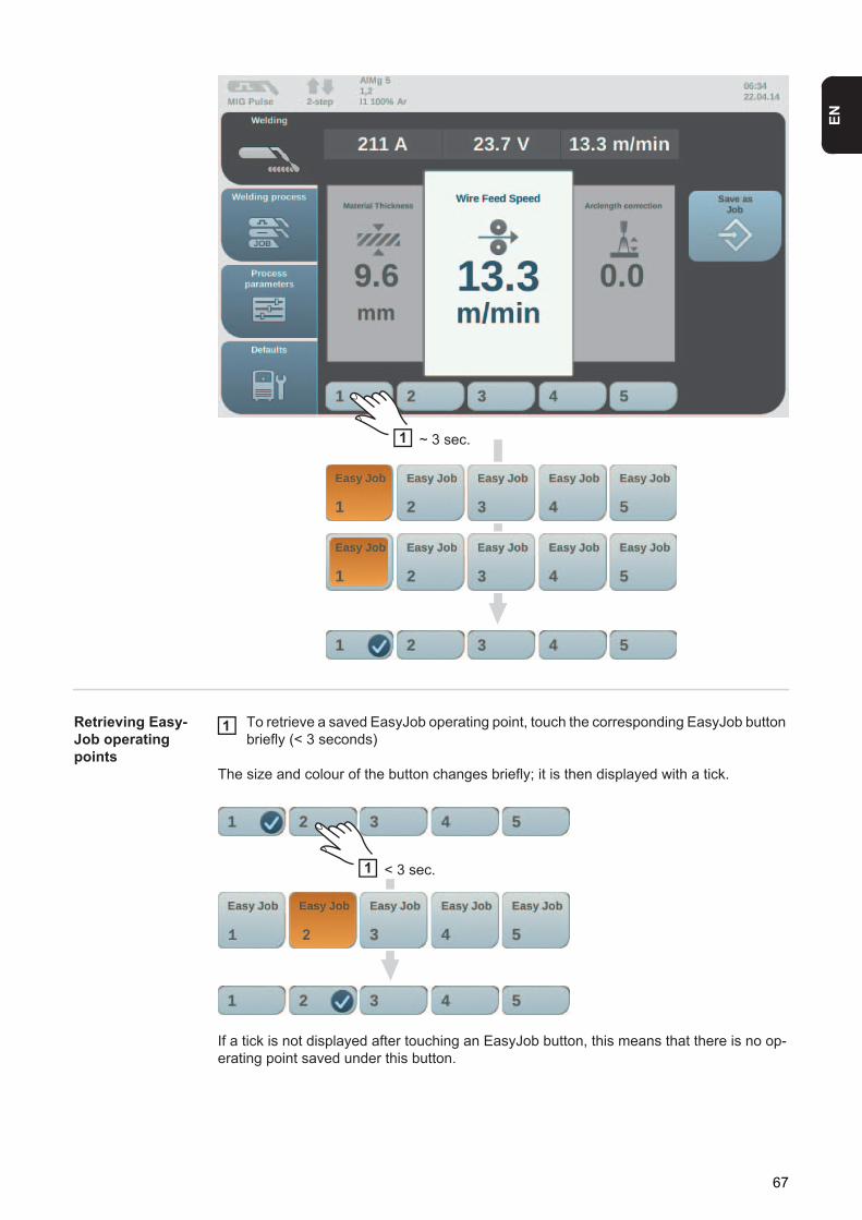
EN
Retrieving Easy-Job operating points
To retrieve a saved EasyJob operating point, touch the corresponding EasyJob button briefly (< 3 seconds)
The size and colour of the button changes briefly; it is then displayed with a tick.
If a tick is not displayed after touching an EasyJob button, this means that there is no op-erating point saved under this button.
1 ~ 3 sec.
1
1 < 3 sec.
1 2
67
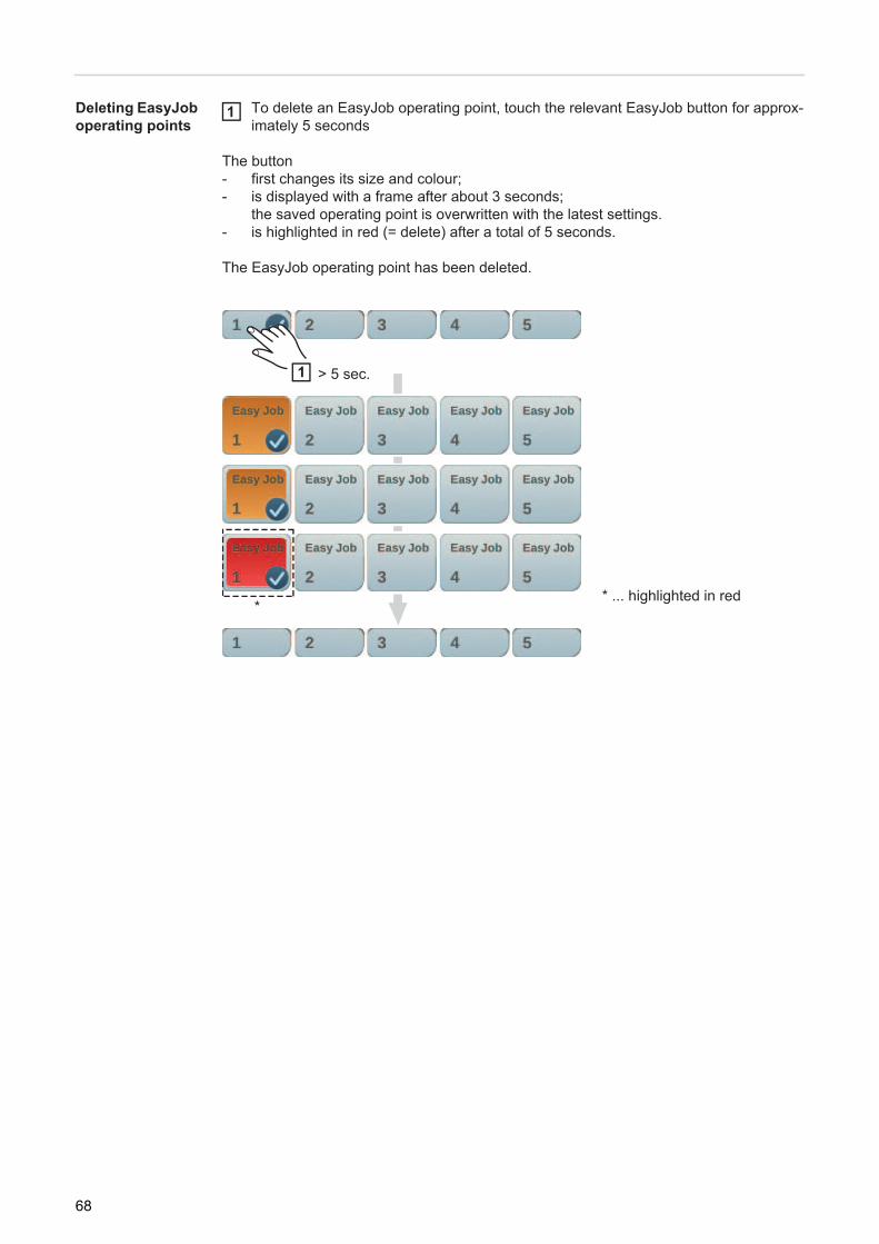
Deleting EasyJob operating points
To delete an EasyJob operating point, touch the relevant EasyJob button for approx-imately 5 seconds
The button - first changes its size and colour;- is displayed with a frame after about 3 seconds;
the saved operating point is overwritten with the latest settings.- is highlighted in red (= delete) after a total of 5 seconds.
The EasyJob operating point has been deleted.
* ... highlighted in red
1
1 > 5 sec.
*
68

EN
Job mode
General Up to 1000 jobs can be stored and retrieved in the power source.This eliminates the need for manual documenting of the welding parameters."Job mode" enhances the quality of automated and manual applications.
Jobs can only be stored when in welding mode. When storing jobs, the process parameters and certain machine defaults are taken into account in addition to the present welding set-tings.
Store settings as a job
Setting the parameters that are to be stored as a job:- Welding parameters- Welding process- Process parameters- Machine defaults (if necessary)
Touch "Store as job" in the right-hand ribbon
The list of empty jobs is displayed.
Empty list List with already stored jobs, e.g. EasyJobs
Touch the "Next" button
1
2
2
3 3
3
69

The next free job is displayed.
Turn the adjusting dial to select the desired locationPress the adjusting dial (or touch the "Next" button)
The keyboard is displayed.
(1) Cancel button(2) OK button (Confirm)(3) Delete button (Delete)(4) Cursor back button(5) Cursor forward button(6) Upper/lower case button(7) Numbers / Special characters button(8) Space bar
5
4
5
45
6
7
7
(1)(2)
(3)
(4)(5)
(6)(7)(6) (7) (8)
70

EN
Enter a job name from the keyboardTouch "OK" and confirm the job name (or press the adjusting dial)
The name is saved and a confirmation that the job has been stored is displayed.
To exit, touch the "Finish" button (or press the adjusting dial)
Weld job - retriev-ing a job
67
NOTE! If an already occupied location is selected when storing a job, a prompt is displayed asking you to confirm that you want to overwrite the existing job.
8
8
NOTE! Before retrieving a job, make sure that the welding system has been in-stalled and set up for the job.
3
1
2
71

Select the "Welding process" button in the left-hand ribbonSelect the "Process" button in the right-hand ribbonSelect the "Job mode" button
A tick (3) appears in the "Job mode" list box.Job mode is activated. In addition, "Weld job" (2) and the data from the most recently retrieved job (1) are dis-played.
Select "Weld job" in the left-hand ribbon
Turn the adjusting dial to select the "Job number" welding parameter (white back-ground)To select the desired job, press the adjusting dial (blue background)Turn the adjusting dial to select the desired job number (blue background)The name of the selected job (4) is displayed above the actual value display (5).Press the adjusting dial to accept the selected job number (white background)
123
(1)
(2)
(3)
4
4
5
6
7
8
(4)
(5)
5
67
8
72

EN
Start welding
Important! "Job number" is the only parameter that can be altered in "Job mode", all the others are read-only
Renaming a job
Touch "Store as job" in the right-hand ribbon(also works in "Job mode")
The job list is displayed.
Turn the adjusting dial to select the job that you want to renameTouch the "Rename job" button
The keyboard is displayed.
9
1
1
2
3
23
73
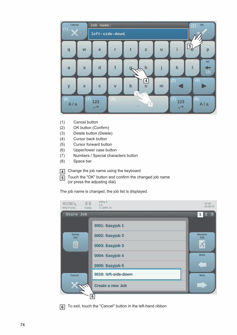
(1) Cancel button(2) OK button (Confirm)(3) Delete button (Delete)(4) Cursor back button(5) Cursor forward button(6) Upper/lower case button(7) Numbers / Special characters button(8) Space bar
Change the job name using the keyboardTouch the "OK" button and confirm the changed job name (or press the adjusting dial)
The job name is changed, the job list is displayed.
To exit, touch the "Cancel" button in the left-hand ribbon
4
5
5
(1)(2)
(3)
(4)(5)
(6)(7)(6) (7) (8)
45
6
6
74
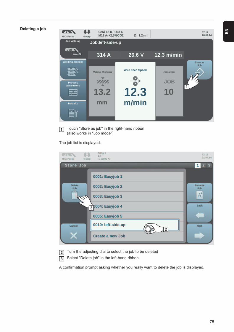
EN
Deleting a job
Touch "Store as job" in the right-hand ribbon(also works in "Job mode")
The job list is displayed.
Turn the adjusting dial to select the job to be deletedSelect "Delete job" in the left-hand ribbon
A confirmation prompt asking whether you really want to delete the job is displayed.
1
1
2
3
23
75

Touch the "Yes" button to delete the selected job
The job name is deleted, the job list is displayed.
To exit, touch the "Cancel" button in the left-hand ribbon
3
4
5
5
76

EN
Welding parameters
Welding parame-ters for MIG/MAG pulse synergic welding
The following welding parameter for MIG/MAG pulse synergic welding can be set and dis-played by pressing the "Welding" button:
Current 1)
Unit ASetting range Depends on the welding process and welding program selected
Before the start of welding, the device automatically displays a standard value based on the programmed parameters. The actual value is displayed during the welding process.Voltage 1)
Unit VSetting range Depends on the welding process and welding program selected
Before the start of welding, the device automatically displays a standard value based on the programmed parameters. The actual value is displayed during the welding process.Material thickness 1)
Unit mm in.Setting range 0.1 - 30.0 mm 2) 0.004 - 1.18 2)
Wire feed speed 1)
Unit m/min ipm.Setting range 0.5 - max. 2) 19.69 - max. 2)
Arc length correctionFor correcting the arc length
Setting range -10 - +10Factory setting 0
- Shorter arc length0 Neutral arc length+ Longer arc lengthPulse/dynamic correctionFor correcting the pulsing energy of a pulsed arc
Setting range -10 - +10Factory setting 0
- Lower droplet detachment force0 Neutral droplet detachment force+ Higher droplet detachment force
77

Welding parame-ters for MIG/MAG standard syner-gic welding
The following welding parameters for MIG/MAG standard synergic welding can be set and displayed by selecting the "Welding" menu button:
Current recomm value 1)
Unit ASetting range depends on the welding process and welding program selected
Before the start of welding, the device automatically displays a standard value based on the programmed parameters. During welding, the actual value is displayed.Voltage recomm value 1)
Unit VSetting range depends on the welding process and welding program selected
Before the start of welding, the device automatically displays a standard value based on the programmed parameters. During welding, the actual value is displayed.Material command value 1)
Unit mm in.Setting range 0.1 - 30.0 mm 2) 0.004 - 1.18 2)
Feeder command value 1)
for setting a harder, more stable arc
Unit m/min ipm.Setting range 0.5 - max. 2) 19.69 - max 2)
Arc length correctionfor correcting the arc length
Setting range -10 - +10Factory setting 0
- shorter arc length0 neutral arc length+ longer arc lengthPulse/dynamic correctionfor influencing the short-circuiting dynamic at the moment of droplet transfer
Setting range -10 - +10Factory setting 0
- harder, more stable arc0 neutral arc+ soft, low-spatter arc
78

EN
Explanation of footnotes
1) Synergic parameterWhen a synergic parameter is changed, the synergic function automatically chang-es all other synergic parameters to match.
The real setting range depends on power source and wire feeder used and on the welding programm.
2) The real setting range depends on the welding program.3) The maximum value depends on the wire feeder used.
79
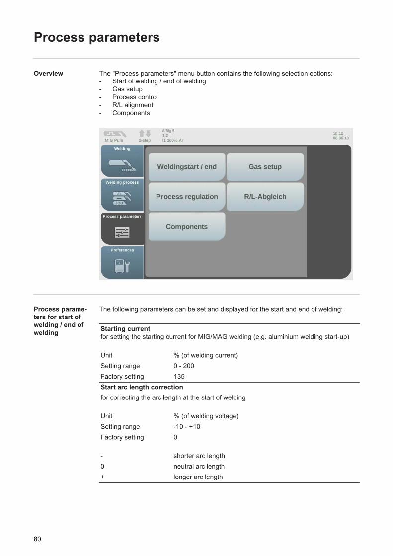
Process parameters
Overview The "Process parameters" menu button contains the following selection options:- Start of welding / end of welding- Gas setup- Process control- R/L alignment- Components
Process parame-ters for start of welding / end of welding
The following parameters can be set and displayed for the start and end of welding:
Starting currentfor setting the starting current for MIG/MAG welding (e.g. aluminium welding start-up)
Unit % (of welding current)Setting range 0 - 200Factory setting 135Start arc length correctionfor correcting the arc length at the start of welding
Unit % (of welding voltage)Setting range -10 - +10Factory setting 0
- shorter arc length0 neutral arc length+ longer arc length
80

EN
Slope 1 for setting the time during which the starting current is decreased or increased to the welding current
Unit sSetting range 0 - 9.9Factory setting 1Slope 2 for setting the time during which the welding current is decreased or increased to the final current.
Unit sSetting range 0 - 9.9Factory setting 1Final current for setting the final current so thata) heat build-up towards the end of welding is prevented andb) the crater is filled (in the case of aluminium)
Unit % (of welding current)Setting range 0 - 200Factory setting 50End arc length correctionfor correcting the arc length at the end of welding
Unit % (of welding voltage)Setting range -10 - +10Factory setting 0
- shorter arc length0 neutral arc length+ longer arc lengthWire withdrawal for setting the wire withdrawal value (= composite value based on backward movement of wire and a time) The wire withdrawal depends on the features of the welding torch.
Unit -Setting range 0 - 10Factory setting 0
81

Process parame-ters for gas setup
The following parameters can be set and displayed for the gas setup:
Process parame-ters for process regulation
The following parameters can be set and displayed for the process control:
Gas pre-flowfor setting the gas flow time before the arc is ignited
Unit sSetting range 0 - 9.9Factory setting 0.1Gas post-flowfor setting the gas post-flow time after the arc has gone out
Unit sSetting range 0 - 9.9Factory setting 0.5
Fusion penetration stabiliserFor setting the max. permitted change in the wire feed speed to ensure that the welding current and hence the fusion penetration is kept stable or constant
The fusion penetration stabiliser parameter is only available when the WP PMC (Welding Process Pulse Multi Control) or WP LSC (Welding Process Low Spatter Control) option has been enabled on the power source.
Unit m/minSetting range 0 - 10.0Factory setting 0
0 The penetration stabiliser is not activated.The wire feed speed remains constant.
0.1 - 10.0 The penetration stabiliser is activated.The welding current remains constant.
82
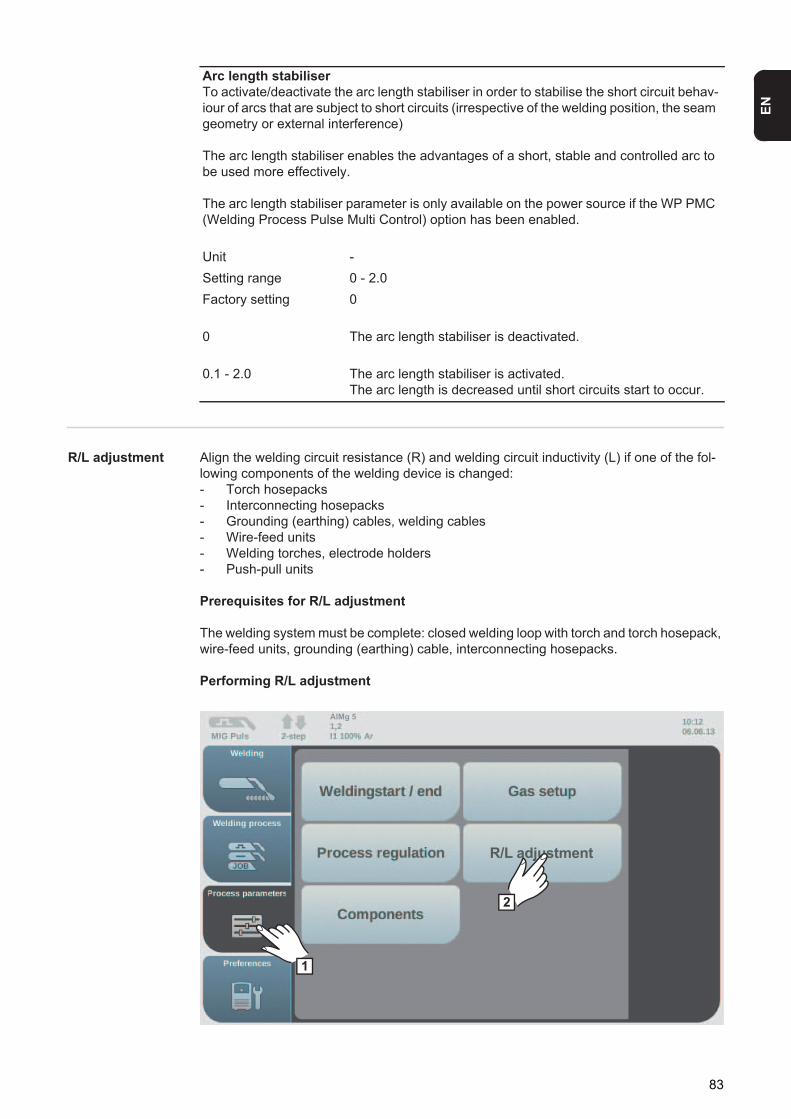
EN
R/L adjustment Align the welding circuit resistance (R) and welding circuit inductivity (L) if one of the fol-lowing components of the welding device is changed:- Torch hosepacks- Interconnecting hosepacks- Grounding (earthing) cables, welding cables- Wire-feed units- Welding torches, electrode holders- Push-pull units
Prerequisites for R/L adjustment
The welding system must be complete: closed welding loop with torch and torch hosepack, wire-feed units, grounding (earthing) cable, interconnecting hosepacks.
Performing R/L adjustment
Arc length stabiliserTo activate/deactivate the arc length stabiliser in order to stabilise the short circuit behav-iour of arcs that are subject to short circuits (irrespective of the welding position, the seam geometry or external interference)
The arc length stabiliser enables the advantages of a short, stable and controlled arc to be used more effectively.
The arc length stabiliser parameter is only available on the power source if the WP PMC (Welding Process Pulse Multi Control) option has been enabled.
Unit -Setting range 0 - 2.0Factory setting 0
0 The arc length stabiliser is deactivated.
0.1 - 2.0 The arc length stabiliser is activated.The arc length is decreased until short circuits start to occur.
1
R/L adjustment
2
AlMg 5
83

Select the "Process parameters" button in the left-hand ribbonSelect the "R/L adjustment" button
The current welding circuit inductivity and welding circuit resistance values are displayed:
Touch "Next" (or press the adjusting dial or the torch trigger)
The second step of the R/L adjustment wizard appears:
Follow the displayed instructions
IMPORTANT! Contact between the earthing clamp and workpiece must be estab-lished on a cleaned area of the workpiece.
12
4,0
3
1,7
AlMg 5
3
5
Make a ground (earth) connection to the workpieceClean the workpiece surface before making a ground (earth) connection!
AlMg 5
4
84

EN
Touch "Next" (or press the adjusting dial or the torch trigger)
The third step of the R/L alignment wizard appears:
Follow the displayed instructionsTouch "Next" (or press the adjusting dial or the torch trigger)
The fourth step of the R/L alignment wizard appears:
Follow the displayed instructionsPress the torch trigger (or touch "Next" or press the adjusting dial)
After a successful measurement, the current values are displayed:
5
7
Remove the gas nozzle at the welding torch
AlMg 5
67
9
Place the contact tube down firmly on the surface of the workpiecePress the torch key or “Next“ to start the R/L adjustment
AlMg 5
89
85

Press "Finish" (or press the adjusting dial)
Process parame-ters for compo-nents
The following process parameters can be set and displayed for the system components of a welding device:
10
Values:
R = 1,3 mOhm (before: 1,7 mOhm)L = 5,0 µH (before: 4,0 µH )
> The R/L adjustment has been performed successfully. To finish the wizard press “Finish“ .
AlMg 5
10
Cooling unit mode to determine whether a cooling unit is to be switched on or off, or operated automatically
Setting range eco / auto / on / off (depending on the cooling unit)Factory setting autoFlow watchdog filter time for setting the time from when the flow watchdog responds until a warning message is output
Unit sSetting range 5 - 25Factory setting 5Feeder inching speed for setting the wire feed speed at which the wire electrode is threaded into the torch hose-pack
Unit m/minSetting range min. - max.Factory setting -
86

Defaults

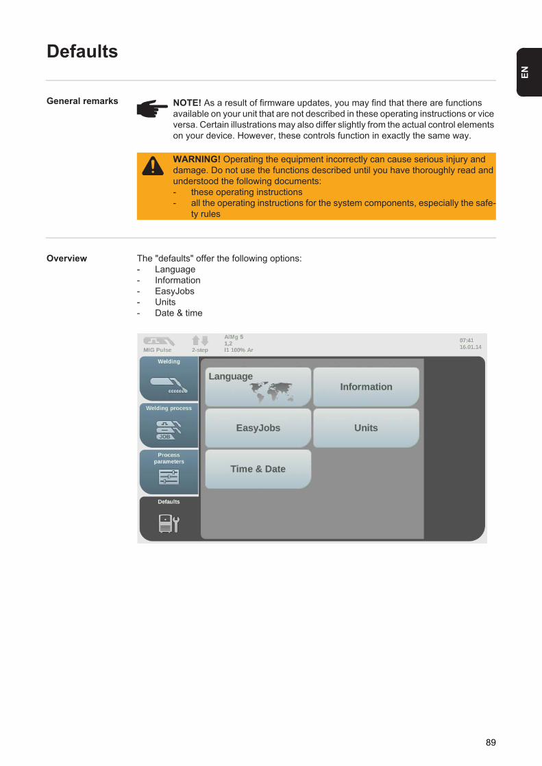
EN
Defaults
General remarks
Overview The "defaults" offer the following options:- Language- Information- EasyJobs- Units- Date & time
NOTE! As a result of firmware updates, you may find that there are functions available on your unit that are not described in these operating instructions or vice versa. Certain illustrations may also differ slightly from the actual control elements on your device. However, these controls function in exactly the same way.
WARNING! Operating the equipment incorrectly can cause serious injury and damage. Do not use the functions described until you have thoroughly read and understood the following documents:- these operating instructions- all the operating instructions for the system components, especially the safe-
ty rules
89

Setting the lan-guage
Select the "Defaults" button in the left-hand ribbonSelect the "Language" button
An overview of the available languages is displayed.
Turn the adjusting dial to select the desired language
Touch the "OK" touch button to exit the language selection(or press the adjusting dial)
The welding parameters are displayed in the selected language.
1
2
12
Language
4
3
4
3
4
90
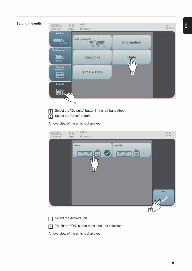
EN
Setting the units
Select the "Defaults" button in the left-hand ribbonSelect the "Units" button
An overview of the units is displayed.
Select the desired unit
Touch the "OK" button to exit the unit selection
An overview of the units is displayed.
1
2
12
3
4
3
4
91

Setting date and time
Select the "Defaults" button in the left-hand ribbonSelect the "Date & time" button
An overview of the date and time is displayed.
Turn the adjusting dial to select the desired parameter Year / Month / Day / Hour / Minute(white background) Press the adjusting dial to set the parameter (blue background) Turn the adjusting dial to set the required value (blue background)Press the adjusting dial to apply the set value (white background)
1
2
12
5
6
3
4
7
3
456
92

EN
Touch the "OK" button to exit the Set date and time routine(or press the adjusting dial)
The settings are displayed.
7
93

94

Troubleshooting and maintenance

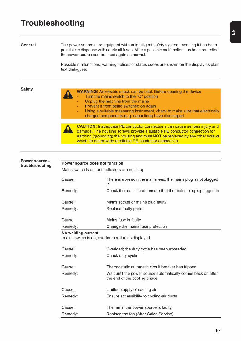
EN
Troubleshooting
General The power sources are equipped with an intelligent safety system, meaning it has been possible to dispense with nearly all fuses. After a possible malfunction has been remedied, the power source can be used again as normal.
Possible malfunctions, warning notices or status codes are shown on the display as plain text dialogues.
Safety
Power source - troubleshooting
WARNING! An electric shock can be fatal. Before opening the device- Turn the mains switch to the "O" position- Unplug the machine from the mains- Prevent it from being switched on again- Using a suitable measuring instrument, check to make sure that electrically
charged components (e.g. capacitors) have discharged
CAUTION! Inadequate PE conductor connections can cause serious injury and damage. The housing screws provide a suitable PE conductor connection for earthing (grounding) the housing and must NOT be replaced by any other screws which do not provide a reliable PE conductor connection.
Power source does not functionMains switch is on, but indicators are not lit up
Cause: There is a break in the mains lead; the mains plug is not plugged in
Remedy: Check the mains lead, ensure that the mains plug is plugged in
Cause: Mains socket or mains plug faultyRemedy: Replace faulty parts
Cause: Mains fuse is faultyRemedy: Change the mains fuse protectionNo welding current mains switch is on, overtemperature is displayed
Cause: Overload; the duty cycle has been exceededRemedy: Check duty cycle
Cause: Thermostatic automatic circuit breaker has trippedRemedy: Wait until the power source automatically comes back on after
the end of the cooling phase
Cause: Limited supply of cooling airRemedy: Ensure accessibility to cooling-air ducts
Cause: The fan in the power source is faultyRemedy: Replace the fan (After-Sales Service)
97

No welding current mains switch is on and indicators are lit up
Cause: Grounding (earthing) connection is incorrectRemedy: Check the grounding (earthing) connection and terminal for cor-
rect polarity
Cause: There is a break in the current cable in the welding torchRemedy: Replace welding torchNothing happens when torch trigger is pressedmains switch is on and indicators are lit up
Cause: The control plug is not plugged inRemedy: Plug in the control plug
Cause: Welding torch or welding torch control line is faultyRemedy: Replace welding torch
Cause: The interconnecting hosepack is faulty or not connected prop-erly
Remedy: Check interconnecting hosepackNo protective gas shieldall other functions are OK
Cause: Gas cylinder is emptyRemedy: Change the gas cylinder
Cause: Gas pressure regulator is faultyRemedy: Change the gas pressure regulator
Cause: The gas hose is not connected, or is damaged or kinkedRemedy: Connect/replace the gas hose, or straighten out kinks
Cause: Welding torch is faultyRemedy: Change the welding torch
Cause: Gas solenoid valve is faultyRemedy: Replace gas solenoid valvePoor weld properties
Cause: Incorrect welding parametersRemedy: Check the settings
Cause: Poor grounding (earthing) connectionRemedy: Ensure good contact to workpiece
Cause: Inadequate or no protective gas shieldRemedy: Check the pressure regulator, gas hose, gas solenoid valve,
torch gas connection, etc.
98

EN
Cause: Welding torch is leakingRemedy: Change the welding torch
Cause: Wrong contact tip, or contact tip is worn outRemedy: Replace the contact tip
Cause: Wrong wire alloy or wrong wire diameterRemedy: Check the wire electrode that has been inserted;
check the weldability of the base metal
Cause: The shielding gas is not suitable for this wire alloyRemedy: Use the correct shielding gas
Irregular wire feed speed
Cause: Braking force has been set too highRemedy: Loosen the brake
Cause: Hole in the contact tip is too narrowRemedy: Use a suitable contact tip
Cause: Faulty inner liner in welding torchRemedy: Check the inner liner for kinks, dirt, etc.
Cause: The feed rollers are not suitable for the wire electrode being used
Remedy: Use suitable feed rollers
Cause: Feed rollers have the wrong contact pressureRemedy: Optimise the contact pressure
Wirefeed problemswhen using long hosepacks
Cause: Incorrect arrangement of hosepackRemedy: Arrange the hosepack in as straight a line as possible, avoid
tight bendsThe welding torch becomes very hot
Cause: The specification of the welding torch is inadequateRemedy: Observe the duty cycle and loading limits
Cause: Only on water-cooled machines: Inadequate coolant flowRemedy: Check coolant fill level, coolant flow, for coolant contamination,
etc.
99

Care, maintenance and disposal
General Under normal operating conditions, the power source requires only a minimum of care and maintenance. However, it is vital to observe some important points to ensure the welding system remains in a usable condition for many years.
Safety
At every start-up - Check mains plug, mains cable, welding torch, interconnecting hosepack and ground-ing (earthing) connection for damage
- Check whether the all-round clearance of 0.5 m (1 ft. 8 in.) is kept to ensure that the cooling air can easily flow and escape.
Every 2 months - If present: clean air filter
Every 6 months
- open the device- clean out the device interior using dry compressed air at reduced pressure- if a lot of dust has accumulated, clean the cooling air ducts.
Updating firm-ware
Important! To update the firmware you need a PC or laptop that is connected to the power source via an Ethernet network.
Get latest firmware (e.g. from the DownloadCenter)File format: official_tpsi_x.x.x-xxxx.ffwEstablish Ethernet connection between PC/laptop and power sourceTransfer the firmware to the power source
Disposal Dispose of in accordance with the applicable national and local regulations.
WARNING! An electric shock can be fatal. Before opening the device- Turn the mains switch to the "O" position- Unplug the machine from the mains- Prevent it from being switched on again- Using a suitable measuring instrument, check to make sure that electrically
charged components (e.g. capacitors) have discharged
NOTE! Air inlets and outlets must never be covered, not even partially.
NOTE! Risk of damage to electronic components. Do not bring air nozzle too close to electronic components.
1
23
100

Appendix


EN
Technical data
Special voltages For devices designed for special voltages, the technical data on the rating plate applies.
For all machines with a permitted mains voltage of up to 460 V: The standard mains plug allows the user to operate with a mains voltage of up to 400 V. For mains voltages up to 460 V fit a mains plug permitted for such use or install the mains supply directly.
103

TPS 320i
1) Interface to a 230/400 V, 50 Hz public grid
Mains voltage (U1 ) 3x 400 VMax. effective primary current (I1eff) 12.3 AMaximum primary current (I1max ) 19.4 AMains fuse 35 A slow-blow
Mains voltage tolerance +/- 15 %Mains frequency 50 / 60 HzCos phi (1) 0.99Max. permitted mains impedance Zmax on PCC1) 95 mOhmRecommended earth-leakage circuit breaker Type B
Welding current range (I2 )MIG/MAG 3 - 320 ARod electrode 10 - 320 AWelding current at 10 min / 40 °C (104 °F) 40 % 60 % 100 %
320 A 260 A 240 AOutput voltage range according to standard characteristic (U2)MIG/MAG 14.2 - 30.0 VRod electrode 20.4 - 32.8 VOpen circuit voltage (U0 peak / U0 r.m.s) 73 V
Degree of protection IP 23Type of cooling AFOvervoltage category IIIPollution level according to IEC60664 3EMC device class ASafety symbols S, CEDimensions l x w x h 706 x 300 x 510 mm
27.8 x 11.8 x 20.1 in.Weight 35.0 kg
77.16 lb.
Max. shielding gas pressure 7.0 bar101.49 psi
Coolant Original Fronius
104

EN
TPS 320i /nc
1) Interface to a 230/400 V, 50 Hz public grid
Mains voltage (U1 ) 3x 380 V 400 V 460 VMax. effective primary current (I1eff) 12.7 A 12.3 A 11.4 AMaximum primary current (I1max ) 20.1 A 19.4 A 18.0 AMains fuse 35 A slow-blow
Mains voltage tolerance +/- 15 %Mains frequency 50 / 60 HzCos phi (1) 0.99Max. permitted mains impedance Zmax on PCC1) 95 mOhmRecommended earth-leakage circuit breaker Type B
Welding current range (I2 )MIG/MAG 3 - 320 ARod electrode 10 - 320 AWelding current at 10 min / 40 °C (104 °F) 40 % 60 % 100 %U1 = 380 - 460 V 320 A 260 A 240 AOutput voltage range according to standard characteristic (U2)MIG/MAG 14.2 - 30.0 VRod electrode 20.4 - 32.8 VOpen circuit voltage (U0 peak / U0 r.m.s) 84 V
Degree of protection IP 23Type of cooling AFOvervoltage category IIIPollution level according to IEC60664 3EMC device class ASafety symbols S, CE, CSADimensions l x w x h 706 x 300 x 510 mm
27.8 x 11.8 x 20.1 in.Weight 33.7 kg
74.30 lb.
Max. shielding gas pressure 7.0 bar101.49 psi
Coolant Original Fronius
105

TPS 320i /600V/nc Mains voltage (U1 ) 3x 575 VMax. effective primary current (I1eff) 10.6 AMaximum primary current (I1max ) 16.7 AMains fuse 35 A slow-blow
Mains voltage tolerance +/- 10 %Mains frequency 50 / 60 HzCos phi (1) 0.99Recommended earth-leakage circuit breaker Type B
Welding current range (I2 )MIG/MAG 3 - 320 ARod electrode 10 - 320 AWelding current at 10 min / 40 °C (104 °F) 40 % 60 % 100 %U1 = 380 - 460 V 320 A 260 A 240 AOutput voltage range according to standard characteristic (U2)MIG/MAG 14.2 - 30.0 VRod electrode 20.4 - 32.8 VOpen circuit voltage (U0 peak / U0 r.m.s) 67 V
Degree of protection IP 23Type of cooling AFOvervoltage category IIIPollution level according to IEC60664 3Safety symbols S, CSADimensions l x w x h 706 x 300 x 510 mm
27.8 x 11.8 x 20.1 in.Weight 32.7 kg
72.09 lb.
Max. shielding gas pressure 7.0 bar101.49 psi
Coolant Original Fronius
106
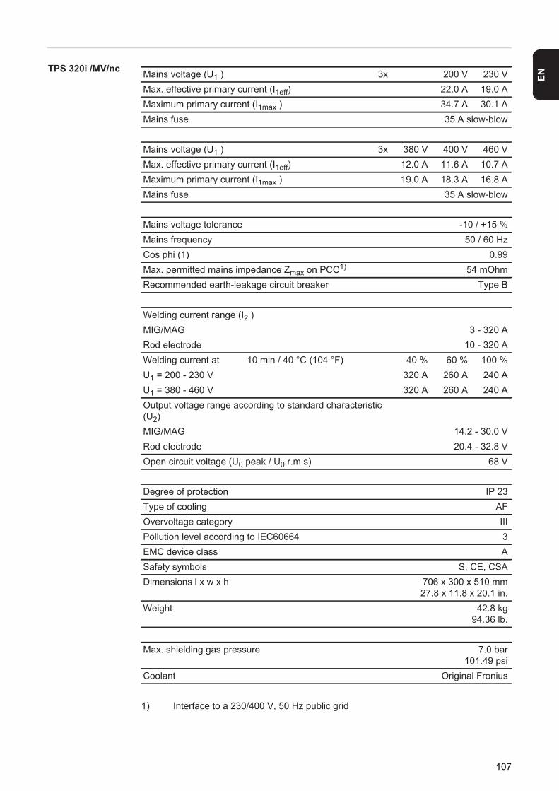
EN
TPS 320i /MV/nc
1) Interface to a 230/400 V, 50 Hz public grid
Mains voltage (U1 ) 3x 200 V 230 VMax. effective primary current (I1eff) 22.0 A 19.0 AMaximum primary current (I1max ) 34.7 A 30.1 AMains fuse 35 A slow-blow
Mains voltage (U1 ) 3x 380 V 400 V 460 VMax. effective primary current (I1eff) 12.0 A 11.6 A 10.7 AMaximum primary current (I1max ) 19.0 A 18.3 A 16.8 AMains fuse 35 A slow-blow
Mains voltage tolerance -10 / +15 %Mains frequency 50 / 60 HzCos phi (1) 0.99Max. permitted mains impedance Zmax on PCC1) 54 mOhmRecommended earth-leakage circuit breaker Type B
Welding current range (I2 )MIG/MAG 3 - 320 ARod electrode 10 - 320 AWelding current at 10 min / 40 °C (104 °F) 40 % 60 % 100 %U1 = 200 - 230 V 320 A 260 A 240 AU1 = 380 - 460 V 320 A 260 A 240 AOutput voltage range according to standard characteristic (U2)MIG/MAG 14.2 - 30.0 VRod electrode 20.4 - 32.8 VOpen circuit voltage (U0 peak / U0 r.m.s) 68 V
Degree of protection IP 23Type of cooling AFOvervoltage category IIIPollution level according to IEC60664 3EMC device class ASafety symbols S, CE, CSADimensions l x w x h 706 x 300 x 510 mm
27.8 x 11.8 x 20.1 in.Weight 42.8 kg
94.36 lb.
Max. shielding gas pressure 7.0 bar101.49 psi
Coolant Original Fronius
107

TPS 400i
1) Interface to a 230/400 V, 50 Hz public grid
Mains voltage (U1 ) 3x 400 VMax. effective primary current (I1eff) 15.9 AMaximum primary current (I1max ) 25.1 AMains fuse 35 A slow-blow
Mains voltage tolerance +/- 15 %Mains frequency 50 / 60 HzCos phi (1) 0.99Max. permitted mains impedance Zmax on PCC1) 92 mOhmRecommended earth-leakage circuit breaker Type B
Welding current range (I2 )MIG/MAG 3 - 400 ARod electrode 10 - 400 AWelding current at 10 min / 40 °C (104 °F) 40 % 60 % 100 %
400 A 360 A 320 AOutput voltage range according to standard characteristic (U2)MIG/MAG 14.2 - 34.0 VRod electrode 20.4 - 36.0 VOpen circuit voltage (U0 peak / U0 r.m.s) 73 V
Degree of protection IP 23Type of cooling AFOvervoltage category IIIPollution level according to IEC60664 3EMC device class ASafety symbols S, CEDimensions l x w x h 706 x 300 x 510 mm
27.8 x 11.8 x 20.1 in.Weight 36.5 kg
80.47 lb.
Max. shielding gas pressure 7.0 bar101.49 psi
Coolant Original Fronius
108

EN
TPS 400i /nc
1) Interface to a 230/400 V, 50 Hz public grid
Mains voltage (U1 ) 3x 380 V 400 V 460 VMax. effective primary current (I1eff) 16.5 A 15.9 A 14.6 AMaximum primary current (I1max ) 26.1 A 25.1 A 23.5 AMains fuse 35 A slow-blow
Mains voltage tolerance +/- 15 %Mains frequency 50 / 60 HzCos phi (1) 0.99Max. permitted mains impedance Zmax on PCC1) 92 mOhmRecommended earth-leakage circuit breaker Type B
Welding current range (I2 )MIG/MAG 3 - 400 ARod electrode 10 - 400 AWelding current at 10 min / 40 °C (104 °F) 40 % 60 % 100 %U1 = 380 - 460 V 400 A 360 A 320 AOutput voltage range according to standard characteristic (U2)MIG/MAG 14.2 - 34.0 VRod electrode 20.4 - 36.0 VOpen circuit voltage (U0 peak / U0 r.m.s) 83 V
Degree of protection IP 23Type of cooling AFOvervoltage category IIIPollution level according to IEC60664 3EMC device class ASafety symbols S, CE, CSADimensions l x w x h 706 x 300 x 510 mm
27.8 x 11.8 x 20.1 in.Weight 35.2 kg
77.60 lb.
Max. shielding gas pressure 7.0 bar101.49 psi
Coolant Original Fronius
109

TPS 400i /600V/nc Mains voltage (U1 ) 3x 575 VMax. effective primary current (I1eff) 14.3 AMaximum primary current (I1max ) 22.6 AMains fuse 35 A slow-blow
Mains voltage tolerance +/- 10 %Mains frequency 50 / 60 HzCos phi (1) 0.99Recommended earth-leakage circuit breaker Type B
Welding current range (I2 )MIG/MAG 3 - 400 ARod electrode 10 - 400 AWelding current at 10 min / 40 °C (104 °F) 40 % 60 % 100 %U1 = 575 V 400 A 360 A 320 AOutput voltage range according to standard characteristic (U2)MIG/MAG 14.2 - 34.0 VRod electrode 20.4 - 36.0 VOpen circuit voltage (U0 peak / U0 r.m.s) 68 V
Degree of protection IP 23Type of cooling AFOvervoltage category IIIPollution level according to IEC60664 3Safety symbols S, CSADimensions l x w x h 706 x 300 x 510 mm
27.8 x 11.8 x 20.1 in.Weight 34.6 kg
76.28 lb.
Max. shielding gas pressure 7.0 bar101.49 psi
Coolant Original Fronius
110

EN
TPS 400i /MV/nc
1) Interface to a 230/400 V, 50 Hz public grid
Mains voltage (U1 ) 3x 200 V 230 VMax. effective primary current (I1eff) 30.5 A 26.4 AMaximum primary current (I1max ) 48.2 A 41.6 AMains fuse 35 A slow-blow
Mains voltage (U1 ) 3x 380 V 400 V 460 VMax. effective primary current (I1eff) 16.2 A 15.5 A 14.0 AMaximum primary current (I1max ) 25.5 A 24.4 A 22.1 AMains fuse 35 A slow-blow
Mains voltage tolerance -10 / +15 %Mains frequency 50 / 60 HzCos phi (1) 0.99Max. permitted mains impedance Zmax on PCC1) 74 mOhmRecommended earth-leakage circuit breaker Type B
Welding current range (I2 )MIG/MAG 3 - 400 ARod electrode 10 - 400 AWelding current at 10 min / 40 °C (104 °F) 40 % 60 % 100 %U1 = 200 - 230 V 400 A 360 A 320 AU1 = 380 - 460 V 400 A 360 A 320 AOutput voltage range according to standard characteristic (U2)MIG/MAG 14.2 - 34.0 VRod electrode 20.4 - 36.0 VOpen circuit voltage (U0 peak / U0 r.m.s) 67 V
Degree of protection IP 23Type of cooling AFOvervoltage category IIIPollution level according to IEC60664 3EMC device class ASafety symbols S, CE, CSADimensions l x w x h 706 x 300 x 510 mm
27.8 x 11.8 x 20.1 in.Weight 47.1 kg
103.84 lb.
Max. shielding gas pressure 7.0 bar101.49 psi
Coolant Original Fronius
111
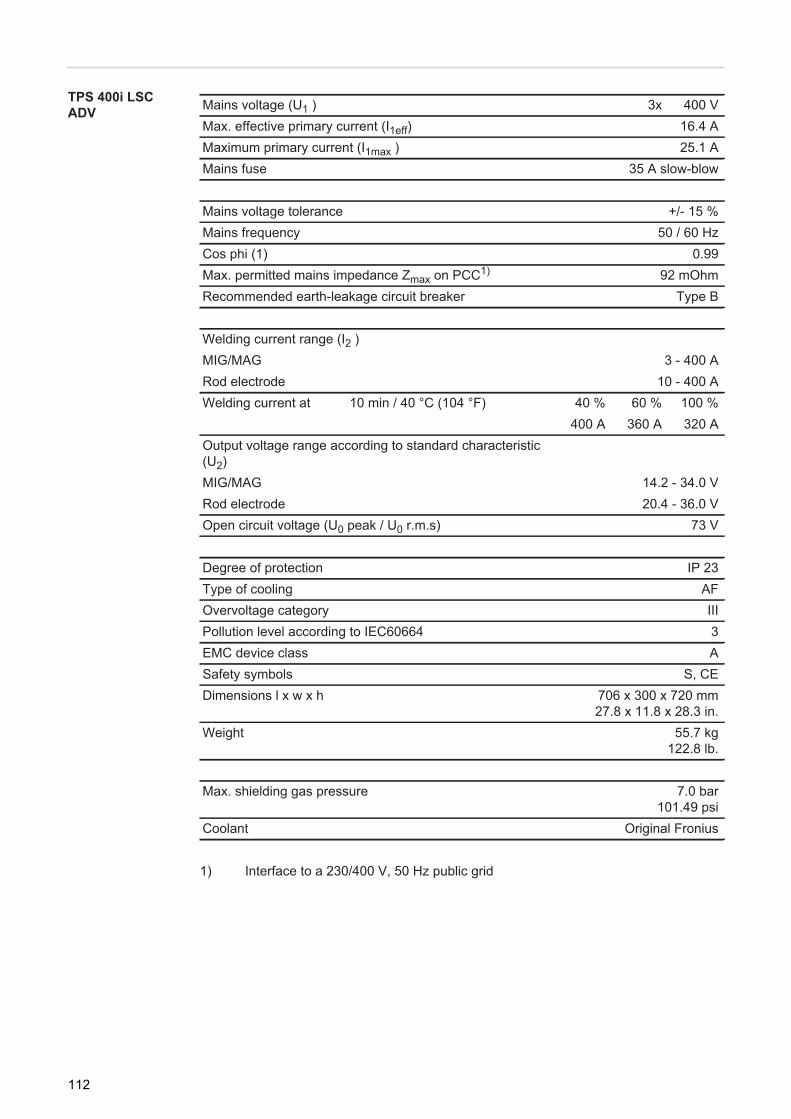
TPS 400i LSC ADV
1) Interface to a 230/400 V, 50 Hz public grid
Mains voltage (U1 ) 3x 400 VMax. effective primary current (I1eff) 16.4 AMaximum primary current (I1max ) 25.1 AMains fuse 35 A slow-blow
Mains voltage tolerance +/- 15 %Mains frequency 50 / 60 HzCos phi (1) 0.99Max. permitted mains impedance Zmax on PCC1) 92 mOhmRecommended earth-leakage circuit breaker Type B
Welding current range (I2 )MIG/MAG 3 - 400 ARod electrode 10 - 400 AWelding current at 10 min / 40 °C (104 °F) 40 % 60 % 100 %
400 A 360 A 320 AOutput voltage range according to standard characteristic (U2)MIG/MAG 14.2 - 34.0 VRod electrode 20.4 - 36.0 VOpen circuit voltage (U0 peak / U0 r.m.s) 73 V
Degree of protection IP 23Type of cooling AFOvervoltage category IIIPollution level according to IEC60664 3EMC device class ASafety symbols S, CEDimensions l x w x h 706 x 300 x 720 mm
27.8 x 11.8 x 28.3 in.Weight 55.7 kg
122.8 lb.
Max. shielding gas pressure 7.0 bar101.49 psi
Coolant Original Fronius
112

EN
TPS 400i LSC ADV /nc
1) Interface to a 230/400 V, 50 Hz public grid
Mains voltage (U1 ) 3x 380 V 400 V 460 VMax. effective primary current (I1eff) 17.1 A 16.4 A 14.8 AMaximum primary current (I1max ) 27.0 A 25.9 A 23.4 AMains fuse 35 A slow-blow
Mains voltage tolerance +/- 15 %Mains frequency 50 / 60 HzCos phi (1) 0.99Max. permitted mains impedance Zmax on PCC1) 92 mOhmRecommended earth-leakage circuit breaker Type B
Welding current range (I2 )MIG/MAG 3 - 400 ARod electrode 10 - 400 AWelding current at 10 min / 40 °C (104 °F) 40 % 60 % 100 %U1 = 380 - 460 V 400 A 360 A 320 AOutput voltage range according to standard characteristic (U2)MIG/MAG 14.2 - 34.0 VRod electrode 20.4 - 36.0 VOpen circuit voltage (U0 peak / U0 r.m.s) 84 V
Degree of protection IP 23Type of cooling AFOvervoltage category IIIPollution level according to IEC60664 3EMC device class ASafety symbols S, CEDimensions l x w x h 706 x 300 x 720 mm
27.8 x 11.8 x 28.4 in.Weight 54.4 kg
119.93 lb.
Max. shielding gas pressure 7.0 bar101.49 psi
Coolant Original Fronius
113
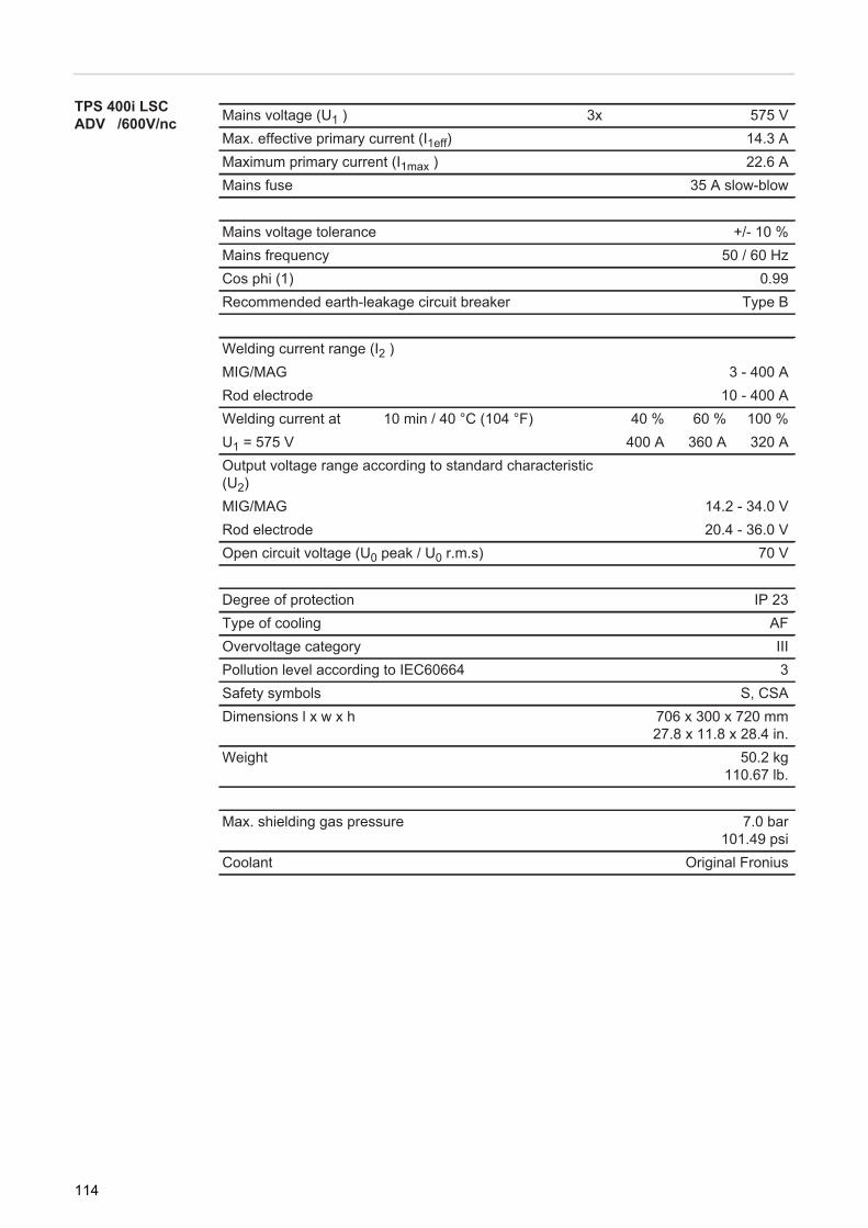
TPS 400i LSC ADV /600V/nc Mains voltage (U1 ) 3x 575 V
Max. effective primary current (I1eff) 14.3 AMaximum primary current (I1max ) 22.6 AMains fuse 35 A slow-blow
Mains voltage tolerance +/- 10 %Mains frequency 50 / 60 HzCos phi (1) 0.99Recommended earth-leakage circuit breaker Type B
Welding current range (I2 )MIG/MAG 3 - 400 ARod electrode 10 - 400 AWelding current at 10 min / 40 °C (104 °F) 40 % 60 % 100 %U1 = 575 V 400 A 360 A 320 AOutput voltage range according to standard characteristic (U2)MIG/MAG 14.2 - 34.0 VRod electrode 20.4 - 36.0 VOpen circuit voltage (U0 peak / U0 r.m.s) 70 V
Degree of protection IP 23Type of cooling AFOvervoltage category IIIPollution level according to IEC60664 3Safety symbols S, CSADimensions l x w x h 706 x 300 x 720 mm
27.8 x 11.8 x 28.4 in.Weight 50.2 kg
110.67 lb.
Max. shielding gas pressure 7.0 bar101.49 psi
Coolant Original Fronius
114

EN
TPS 400i LSC ADV /MV/nc
1) Interface to a 230/400 V, 50 Hz public grid
Mains voltage (U1 ) 3x 200 V 230 VMax. effective primary current (I1eff) 30.5 A 26.4 AMaximum primary current (I1max ) 48.2 A 41.6 AMains fuse 35 A slow-blow
Mains voltage (U1 ) 3x 380 V 400 V 460 VMax. effective primary current (I1eff) 16.2 A 15.5 A 14.0 AMaximum primary current (I1max ) 25.5 A 24.4 A 22.1 AMains fuse 35 A slow-blow
Mains voltage tolerance -10 / +15 %Mains frequency 50 / 60 HzCos phi (1) 0.99Max. permitted mains impedance Zmax on PCC1) 45 mOhmRecommended earth-leakage circuit breaker Type B
Welding current range (I2 )MIG/MAG 3 - 400 ARod electrode 10 - 400 AWelding current at 10 min / 40 °C (104 °F) 40 % 60 % 100 %U1 = 200 - 230 V 400 A 360 A 320 AU1 = 380 - 460 V 400 A 360 A 320 AOutput voltage range according to standard characteristic (U2)MIG/MAG 14.2 - 34.0 VRod electrode 20.4 - 36.0 VOpen circuit voltage (U0 peak / U0 r.m.s) 67 V
Degree of protection IP 23Type of cooling AFOvervoltage category IIIPollution level according to IEC60664 3EMC device class ASafety symbols S, CE, CSADimensions l x w x h 706 x 300 x 720 mm
27.8 x 11.8 x 28.4 in.Weight 63.6 kg
140.24 lb.
Max. shielding gas pressure 7.0 bar101.49 psi
Coolant Original Fronius
115

TPS 500i
1) Interface to a 230/400 V, 50 Hz public grid
Mains voltage (U1 ) 3x 400 VMax. effective primary current (I1eff) 23.7 AMaximum primary current (I1max ) 37.5 AMains fuse 35 A slow-blow
Mains voltage tolerance +/- 15 %Mains frequency 50 / 60 HzCos phi (1) 0.99Max. permitted mains impedance Zmax on PCC1) 49 mOhmRecommended earth-leakage circuit breaker Type B
Welding current range (I2 )MIG/MAG 3 - 500 ARod electrode 10 - 500 AWelding current at 10 min / 40 °C (104 °F) 40 % 60 % 100 %
500 A 430 A 360 AOutput voltage range according to standard characteristic (U2)MIG/MAG 14.2 - 39.0 VRod electrode 20.4 - 40.0 VOpen circuit voltage (U0 peak / U0 r.m.s) 71 V
Degree of protection IP 23Type of cooling AFOvervoltage category IIIPollution level according to IEC60664 3EMC device class ASafety symbols S, CEDimensions l x w x h 706 x 300 x 510 mm
27.8 x 11.8 x 20.1 in.Weight 38 kg
83.8 lb.
Max. shielding gas pressure 7.0 bar101.49 psi
Coolant Original Fronius
116

EN
TPS 500i /nc
1) Interface to a 230/400 V, 50 Hz public grid
Mains voltage (U1 ) 3x 380 V 400 V 460 VMax. effective primary current (I1eff) 24.5 A 23.7 A 21.9 AMaximum primary current (I1max ) 38.8 A 37.5 A 34.7 AMains fuse 35 A slow-blow
Mains voltage tolerance - 10 / + 15 %Mains frequency 50 / 60 HzCos phi (1) 0.99Max. permitted mains impedance Zmax on PCC1) 49 mOhmRecommended earth-leakage circuit breaker Type B
Welding current range (I2 )MIG/MAG 3 - 500 ARod electrode 10 - 500 AWelding current at 10 min / 40 °C (104 °F) 40 % 60 % 100 %U1 = 380 - 460 V 500 A 430 A 360 AOutput voltage range according to standard characteristic (U2)MIG/MAG 14.2 - 39.0 VRod electrode 20.4 - 40.0 VOpen circuit voltage (U0 peak / U0 r.m.s) 82 V
Degree of protection IP 23Type of cooling AFOvervoltage category IIIPollution level according to IEC60664 3EMC device class ASafety symbols S, CE, CSADimensions l x w x h 706 x 300 x 510 mm
27.8 x 11.8 x 20.1 in.Weight 36.7 kg
80.9 lb.
Max. shielding gas pressure 7.0 bar101.49 psi
Coolant Original Fronius
117

TPS 500i /600V/nc Mains voltage (U1 ) 3x 575 VMax. effective primary current (I1eff) 19.7 AMaximum primary current (I1max ) 31.2 AMains fuse 35 A slow-blow
Mains voltage tolerance +/- 10 %Mains frequency 50 / 60 HzCos phi (1) 0.99Recommended earth-leakage circuit breaker Type B
Welding current range (I2 )MIG/MAG 3 - 500 ARod electrode 10 - 500 AWelding current at 10 min / 40 °C (104 °F) 40 % 60 % 100 %U1 = 575 V 500 A 430 A 360 AOutput voltage range according to standard characteristic (U2)MIG/MAG 14.2 - 39.0 VRod electrode 20.4 - 40.0 VOpen circuit voltage (U0 peak / U0 r.m.s) 71 V
Degree of protection IP 23Type of cooling AFOvervoltage category IIIPollution level according to IEC60664 3Safety symbols S, CSADimensions l x w x h 706 x 300 x 510 mm
27.8 x 11.8 x 20.1 in.Weight 34.9 kg
76.94 lb.
Max. shielding gas pressure 7 bar101.49 psi
Coolant Original Fronius
118
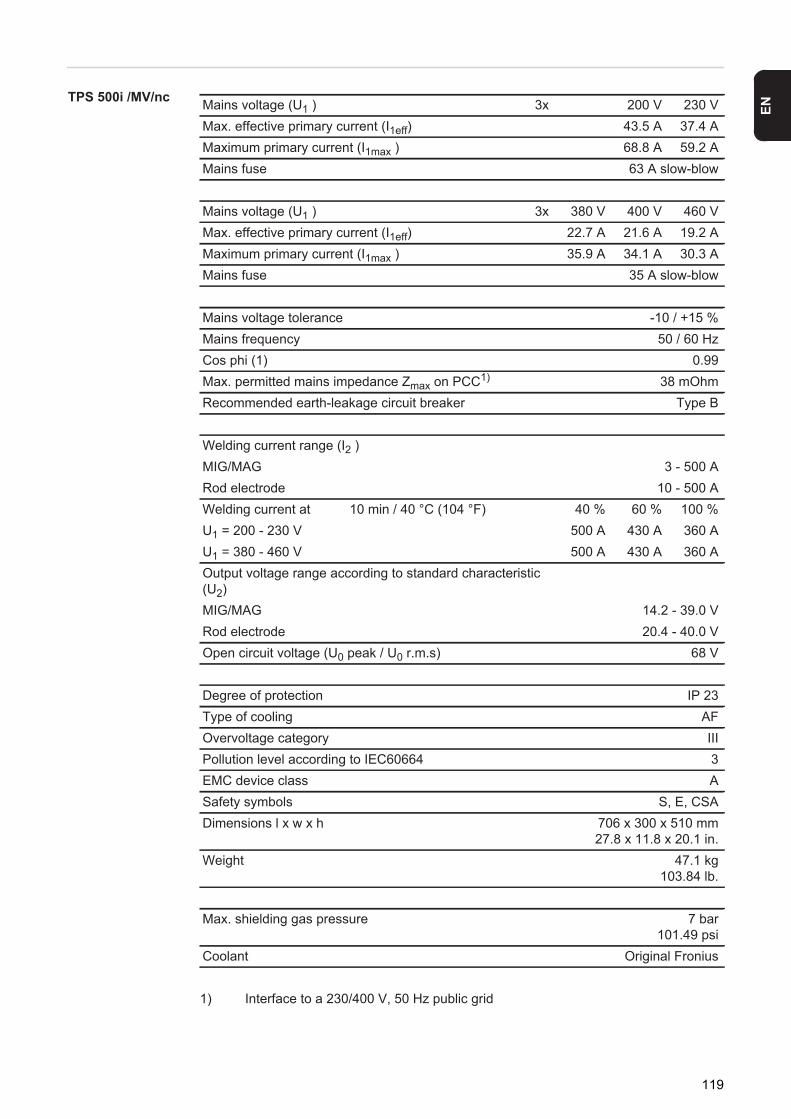
EN
TPS 500i /MV/nc
1) Interface to a 230/400 V, 50 Hz public grid
Mains voltage (U1 ) 3x 200 V 230 VMax. effective primary current (I1eff) 43.5 A 37.4 AMaximum primary current (I1max ) 68.8 A 59.2 AMains fuse 63 A slow-blow
Mains voltage (U1 ) 3x 380 V 400 V 460 VMax. effective primary current (I1eff) 22.7 A 21.6 A 19.2 AMaximum primary current (I1max ) 35.9 A 34.1 A 30.3 AMains fuse 35 A slow-blow
Mains voltage tolerance -10 / +15 %Mains frequency 50 / 60 HzCos phi (1) 0.99Max. permitted mains impedance Zmax on PCC1) 38 mOhmRecommended earth-leakage circuit breaker Type B
Welding current range (I2 )MIG/MAG 3 - 500 ARod electrode 10 - 500 AWelding current at 10 min / 40 °C (104 °F) 40 % 60 % 100 %U1 = 200 - 230 V 500 A 430 A 360 AU1 = 380 - 460 V 500 A 430 A 360 AOutput voltage range according to standard characteristic (U2)MIG/MAG 14.2 - 39.0 VRod electrode 20.4 - 40.0 VOpen circuit voltage (U0 peak / U0 r.m.s) 68 V
Degree of protection IP 23Type of cooling AFOvervoltage category IIIPollution level according to IEC60664 3EMC device class ASafety symbols S, E, CSADimensions l x w x h 706 x 300 x 510 mm
27.8 x 11.8 x 20.1 in.Weight 47.1 kg
103.84 lb.
Max. shielding gas pressure 7 bar101.49 psi
Coolant Original Fronius
119
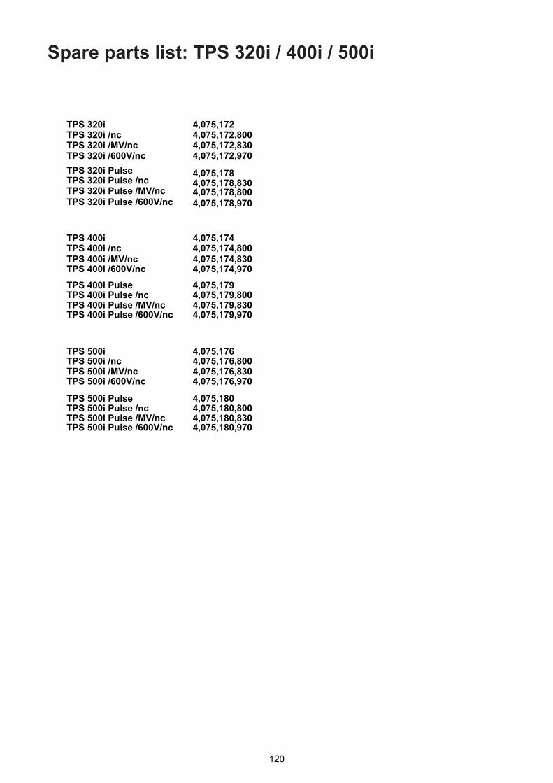
Spare parts list: TPS 320i / 400i / 500i
120

121
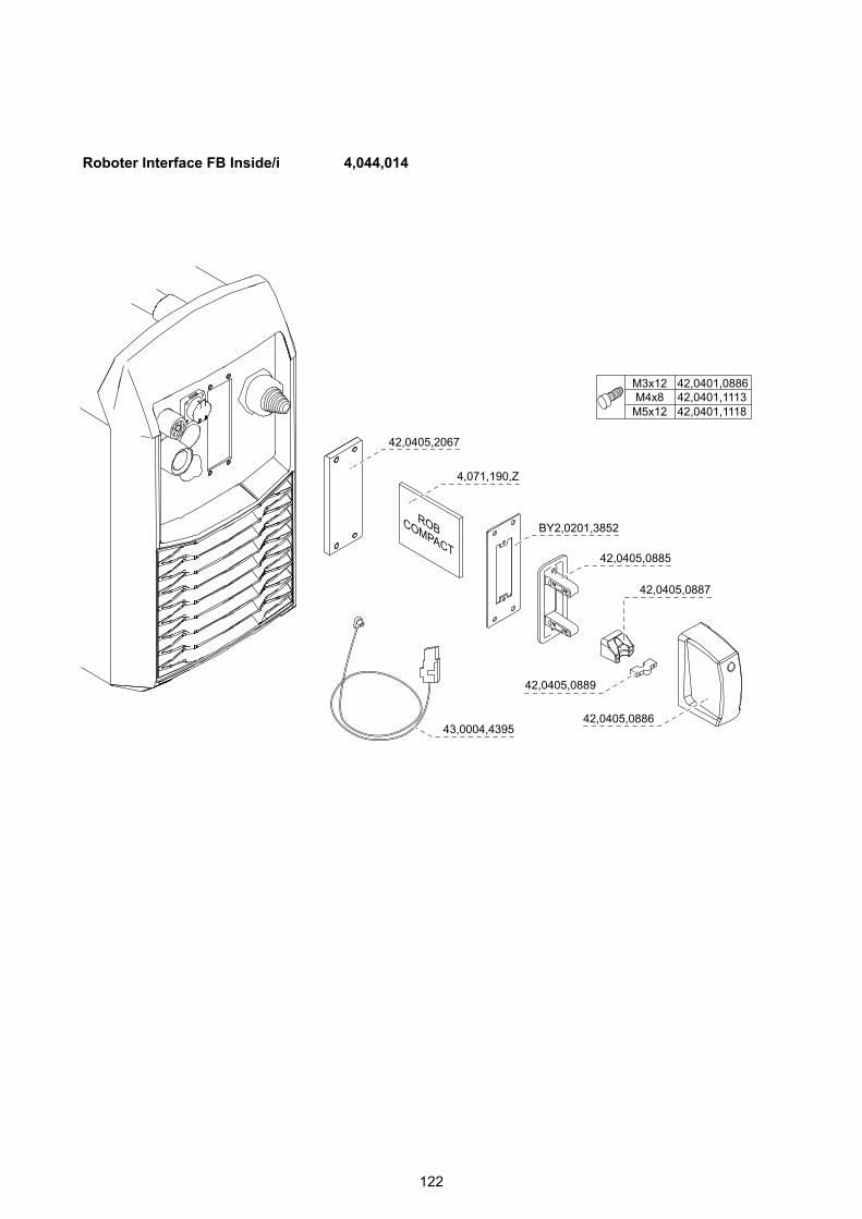
122

123

124

125
EN

FRONIUS INTERNATIONAL GMBHFroniusplatz 1, A-4600 Wels, Austria
Tel: +43 (0)7242 241-0, Fax: +43 (0)7242 241-3940E-Mail: [email protected]
www.fronius.com
www.fronius.com/addressesUnder http://www.fronius.com/addresses you will find all addresses
of our Sales & service partners and Locations