· krautkramer usn 58 series issue 04, 05/04 0-1 contents krautkramer usn 58 series issue 04,...
TRANSCRIPT


Krautkramer USN 58 Series Issue 04, 05/04 0-1
Contents
Krautkramer USN 58 Series Issue 04, 05/04 0-1
Contents
1 Understanding the Keypad,Menu System, and Displays ............. 1-1
1.1 Battery installation ................................. 1-2
1.2 Powering On and Off the Instrument .... 1-5
1.3 Keypad and Knob Features ................... 1-5
1.4 USN 58 Menus and Functions ............... 1-81.4.1 Home Menu System ..................... 1-9
1.4.2 Test Menus and Functions ...........1-16
1.5 Display Screen Features .......................1-16
Definition of Display Icons ......................1-19
1.6 Features of the USN 58 .........................1-19
1.7 What’s in this Manual ...........................1-21
1.8 Overview of Optional Features .............1-23
1.8.1 Determing Which Optional Featuresare Installed in Your USN 58 ........1-23
1.8.2 How Options are Dealt with inThis Manual .................................1-24
2 Setup and Calibration of the USN 58 . 2-1
2.1 Initial Instrument Setup ......................... 2-2
Specifying the Installed Battery Type ....... 2-2
2.1.1 Regional Settings-Language, Unitsof Measurement, Date, and Time .. 2-4
Setting the Operating Language ............... 2-4
Setting the Date ....................................... 2-4
Setting the Time....................................... 2-5
Setting the Units of Measurement ............ 2-5
2.1.2 Display Appearance ...................... 2-6
Setting the Display Brightness ................. 2-6
Selecting a Display Grid .......................... 2-6
Selecting Reverse Video Mode–58R ........ 2-7
Setting the Display Color–58L .................. 2-7
Setting the A-Scan Color–58L .................. 2-8
Setting the A-Scan Style ......................... 2-8
2.2 Installing a Probe .................................. 2-8
2.2.1 Connecting a Probe ...................... 2-8
2.2.2 Configuring the Instrument toMatch the Probe Type ................... 2-9
1 Understanding the Keypad,Menu System, and Displays ............. 1-1
1.1 Battery installation ................................. 1-2
1.2 Powering On and Off the Instrument .... 1-5
1.3 Keypad and Knob Features ................... 1-5
1.4 USN 58 Menus and Functions ............... 1-8
1.4.1 Home Menu System ..................... 1-9
1.4.2 Test Menus and Functions ...........1-16
1.5 Display Screen Features .......................1-16
Definition of Display Icons ......................1-19
1.6 Features of the USN 58 .........................1-19
1.7 What’s in this Manual ...........................1-21
1.8 Overview of Optional Features .............1-231.8.1 Determing Which Optional Features
are Installed in Your USN 58 ........1-23
1.8.2 How Options are Dealt with inThis Manual .................................1-24
2 Setup and Calibration of the USN 58 . 2-1
2.1 Initial Instrument Setup ......................... 2-2
Specifying the Installed Battery Type ....... 2-2
2.1.1 Regional Settings-Language, Unitsof Measurement, Date, and Time .. 2-4
Setting the Operating Language ............... 2-4
Setting the Date ....................................... 2-4
Setting the Time....................................... 2-5
Setting the Units of Measurement ............ 2-5
2.1.2 Display Appearance ...................... 2-6
Setting the Display Brightness ................. 2-6
Selecting a Display Grid .......................... 2-6
Selecting Reverse Video Mode–58R ........ 2-7
Setting the Display Color–58L .................. 2-7
Setting the A-Scan Color–58L .................. 2-8
Setting the A-Scan Style ......................... 2-8
2.2 Installing a Probe .................................. 2-8
2.2.1 Connecting a Probe ...................... 2-8
2.2.2 Configuring the Instrument toMatch the Probe Type ................... 2-9

0-2 Issue 04, 05/04 Krautkramer USN 58 Series
Contents
0-2 Issue 04, 05/04 Krautkramer USN 58 Series
Contents
Selecting Probe Type ............................... 2-9
Specifying the Probe Frequency .............. 2-9
Modifying the Signal Ratio to Noise byChanging the Damping Level ..................2-11
2.3 Adjusting the A-Scan ............................2-112.3.1 Setting the A-Scan Range ...........2-11
Setting The A-Scan Range ......................2-14
2.3.2 Setting the Display Delay ............2-14
2.3.3 Defining the Display StartingPoint ............................................2-14
2.3.4 Adjusting the Pulser RepetitionFrequency (PRF) ..........................2-15
2.3.5 Selecting a Rectification Mode ....2-16
2.3.6 Selecting the Pulser Type ............2-17
2.3.7 Setting the Pulser VOLTAGE orENERGY Level ............................2-18
2.3.8 Selecting the Pulser Width(SQUARE Pulser Types only) .......2-18
2.3.9 Setting the A-Scan REJECTLevel ............................................2-19
2.4 Calibrating the Instrument ....................2-19
2.4.1 Pre-calibration Check List ............2-19
2.4.2 Using AUTOCAL to CalibrateUSN 58 Series Instruments .........2-20
Checking Calibration Results ..................2-22
3 Configuring Your Instrumentfor Measurement ............................... 3-1
3.1 Configuring the A and B-Gates ............. 3-2
3.1.1 Positioning Gates ......................... 3-4
Setting a Gate’s Starting Point ................. 3-4
Adjusting a Gate’s Width .......................... 3-6
Setting a Gate’s Threshold(Vertical Position) ..................................... 3-6
3.1.2 Selecting the Gate DetectionMethod ......................................... 3-6
Setting the A-Scan Signal-DetectionMethod .................................................... 3-6
3.1.3 Selecting the Gate to beMagnified ...................................... 3-8
3.1.4 Setting Gate Alarms andTTL Outputs ................................. 3-8

Krautkramer USN 58 Series Issue 04, 05/04 0-3
Contents
Krautkramer USN 58 Series Issue 04, 05/04 0-3
Contents
Defining Gate-Alarm Logic ....................... 3-9
Turning the Audible Alarm On or Off ......... 3-9
Assigning TTL Outputs / Alarm IndicationLights to Gates and/or Limits ................... 3-9
3.1.5 Clearing TTL Outputs and/orWarning Lights .............................3-10
3.1.6 Setting the Units of AmplitudeMeasurement ...............................3-11
3.2 Setting the Minimum and MaximumMaterial-Thickness Limits ....................3-11
Setting the Minimum and MaximumThickness Limits ....................................3-12
3.3 Setting the Freeze-Mode Action ...........3-12
Selecting the Freeze-Mode Action ..........3-12
3.4 Using Angle Beam Probes and the TRIGMenu ......................................................3-143.4.1 Setting Angle Beam Probe
Characteristics.............................3-15
3.4.2 Indicating Leg with Color (58L) .....3-16
3.5 Displaying Measured Readings............3-16
Assigning Measured Readings to theDisplayed Reading Boxes .......................3-18
3.6 Saving the Instrument Configuration in aData Set .................................................3-20
3.7 Using the Master Lock (all models)Function or the Lock Key (58L) toPrevent Adjustment ..............................3-21
Locking the Gain and Function RotaryKnobs ....................................................3-21
4 Using the Test Menu .......................... 4-1
4.1 Accessing the TEST Menu..................... 4-2
4.2 Setting the Gain ..................................... 4-4
4.2.1 Changing the Gain-AdjustmentIncrement (dB STEP) ................... 4-4
4.2.2 Setting the User-Defined GainStep.............................................. 4-6
4.3 Using the dB Reference Feature ............ 4-6
4.4 Changing the Displayed VIEW .............. 4-8
Defining Gate-Alarm Logic ....................... 3-9
Turning the Audible Alarm On or Off ......... 3-9
Assigning TTL Outputs / Alarm IndicationLights to Gates and/or Limits ................... 3-9
3.1.5 Clearing TTL Outputs and/orWarning Lights .............................3-10
3.1.6 Setting the Units of AmplitudeMeasurement ...............................3-11
3.2 Setting the Minimum and MaximumMaterial-Thickness Limits ....................3-11
Setting the Minimum and MaximumThickness Limits ....................................3-12
3.3 Setting the Freeze-Mode Action ...........3-12Selecting the Freeze-Mode Action ..........3-12
3.4 Using Angle Beam Probes and the TRIGMenu ......................................................3-143.4.1 Setting Angle Beam Probe
Characteristics.............................3-15
3.4.2 Indicating Leg with Color (58L) .....3-16
3.5 Displaying Measured Readings............3-16
Assigning Measured Readings to theDisplayed Reading Boxes .......................3-18
3.6 Saving the Instrument Configuration in aData Set .................................................3-20
3.7 Using the Master Lock (all models)Function or the Lock Key (58L) toPrevent Adjustment ..............................3-21
Locking the Gain and Function RotaryKnobs ....................................................3-21
4 Using the Test Menu .......................... 4-1
4.1 Accessing the TEST Menu..................... 4-2
4.2 Setting the Gain ..................................... 4-4
4.2.1 Changing the Gain-AdjustmentIncrement (dB STEP) ................... 4-4
4.2.2 Setting the User-Defined GainStep.............................................. 4-6
4.3 Using the dB Reference Feature ............ 4-6
4.4 Changing the Displayed VIEW .............. 4-8

0-4 Issue 04, 05/04 Krautkramer USN 58 Series
Contents
0-4 Issue 04, 05/04 Krautkramer USN 58 Series
Contents
4.5 Navigating Through a DataLogger File and Attaching Notes .........4-10
4.6 Magnifying the Contents of a Gate .......4-10
Selecting the Gate to Be Magnified .........4-13
4.7 Resetting Latched Alarms ....................4-13
4.8 Large Display Box-Specifying theContents (LRG DISP) ............................4-13
4.9 Freezing the A-Scan Display ................4-15
4.9.1 Working in the Behind the FreezeMode ...........................................4-15
4.10 Accessing the HELP SCREENS ...........4-17
5 Storing and Outputting Data ............ 5-1
5.1 Data Set and Data Logger Files ............... 5-45.1.1 Creating Data Set Files ................. 5-6
5.1.2 Creating Data Logger Files ............ 5-6
5.1.3 Editing Active Files ....................... 5-8
5.2 Storing Thickness Measurements inData Logger Files ..................................5-10
5.3 Recalling Existing Data Files ...............5-10
5.3.1 Previewing Existing Data Files ....5-11
5.4 Deleting (CLEARING) Existing DataFiles .......................................................5-11
5.5 Creating a Memo ...................................5-12
5.5.1 Including a File’s Memo as Part ofa Report ......................................5-12
5.6 Creating a Report Header .....................5-12
5.6.1 Including a Report Header In aPrinted Report .............................5-14
5.7 Entering and Editing Notes forAttachment to ThicknessMeasurements .......................................5-14
5.7.1 Including a Notes In a PrintedReport .........................................5-16
5.8 Printing a Report ...................................5-16
5.9 Outputting to a Printer ..........................5-18
5.9.1 Specifying the Printer Type andBaud Rate ...................................5-18
5.9.2 Setting the COPY Key Function ...5-19
4.5 Navigating Through a DataLogger File and Attaching Notes .........4-10
4.6 Magnifying the Contents of a Gate .......4-10
Selecting the Gate to Be Magnified .........4-13
4.7 Resetting Latched Alarms ....................4-13
4.8 Large Display Box-Specifying theContents (LRG DISP) ............................4-13
4.9 Freezing the A-Scan Display ................4-154.9.1 Working in the Behind the Freeze
Mode ...........................................4-15
4.10 Accessing the HELP SCREENS ...........4-17
5 Storing and Outputting Data ............ 5-1
5.1 Data Set and Data Logger Files ............... 5-4
5.1.1 Creating Data Set Files ................. 5-6
5.1.2 Creating Data Logger Files ............ 5-6
5.1.3 Editing Active Files ....................... 5-8
5.2 Storing Thickness Measurements inData Logger Files ..................................5-10
5.3 Recalling Existing Data Files ...............5-105.3.1 Previewing Existing Data Files ....5-11
5.4 Deleting (CLEARING) Existing DataFiles .......................................................5-11
5.5 Creating a Memo ...................................5-12
5.5.1 Including a File’s Memo as Part ofa Report ......................................5-12
5.6 Creating a Report Header .....................5-125.6.1 Including a Report Header In a
Printed Report .............................5-14
5.7 Entering and Editing Notes forAttachment to ThicknessMeasurements .......................................5-14
5.7.1 Including a Notes In a PrintedReport .........................................5-16
5.8 Printing a Report ...................................5-16
5.9 Outputting to a Printer ..........................5-185.9.1 Specifying the Printer Type and
Baud Rate ...................................5-18
5.9.2 Setting the COPY Key Function ...5-19

Krautkramer USN 58 Series Issue 04, 05/04 0-5
Contents
Krautkramer USN 58 Series Issue 04, 05/04 0-5
Contents
5.10 Outputting to a Computer via theRS-232 Serial Port .................................5-20
5.10.1 Specifying the Baud Rate ............5-20
5.10.2 Loss of Signal ..............................5-20
6 Advanced Base-ModelFeatures ............................................. 6-1
6.1 Noise Immunization .............................. 6-2
6.2 Using SMART VIEW ............................... 6-3
6.3 Using A-Scan Enhancement AnalogDisplay Emulation ................................. 6-4
6.3.1 SPARKLE Intensity Variation(58L only) ...................................... 6-4
6.3.2 Baseline Break ............................. 6-4
6.4 AWS D1.1 Weld Rating Feature .............. 6-7
6.5 Resetting the Instrument ....................... 6-9
7 I/O Ports Technical Data .................... 7-1
7.1 Sending Readings to Other Devices ..... 7-2
7.2 Analog Output ........................................ 7-3
7.3 Remote Control of the USN 58 .............. 7-6
7.4 Remote Codes for the USN 58 ............... 7-7
8 DAC/TCG Option ................................ 8-1
8.1 Using TCG .............................................. 8-28.1.1 Recording the TCG Reference
Points ........................................... 8-3
8.1.2 Working with TCG ......................... 8-4
Using TCG ATTENUATION ....................... 8-4
8.2 Using DAC............................................... 8-68.2.1 Recording the DAC Curve ............. 8-6
8.2.2 Working with DAC ......................... 8-7
Creating DAC Offset Curves .................... 8-9
Adjusting the Applied Gain UsingTRANSFER CORRECTION ..................... 8-9
8.3 Editing DAC Curve and TCGReference Points ...................................8-10
5.10 Outputting to a Computer via theRS-232 Serial Port .................................5-205.10.1 Specifying the Baud Rate ............5-20
5.10.2 Loss of Signal ..............................5-20
6 Advanced Base-ModelFeatures ............................................. 6-1
6.1 Noise Immunization .............................. 6-2
6.2 Using SMART VIEW ............................... 6-3
6.3 Using A-Scan Enhancement AnalogDisplay Emulation ................................. 6-4
6.3.1 SPARKLE Intensity Variation(58L only) ...................................... 6-4
6.3.2 Baseline Break ............................. 6-4
6.4 AWS D1.1 Weld Rating Feature .............. 6-7
6.5 Resetting the Instrument ....................... 6-9
7 I/O Ports Technical Data .................... 7-1
7.1 Sending Readings to Other Devices ..... 7-2
7.2 Analog Output ........................................ 7-3
7.3 Remote Control of the USN 58 .............. 7-6
7.4 Remote Codes for the USN 58 ............... 7-7
8 DAC/TCG Option ................................ 8-1
8.1 Using TCG .............................................. 8-2
8.1.1 Recording the TCG ReferencePoints ........................................... 8-3
8.1.2 Working with TCG ......................... 8-4
Using TCG ATTENUATION ....................... 8-4
8.2 Using DAC............................................... 8-6
8.2.1 Recording the DAC Curve ............. 8-6
8.2.2 Working with DAC ......................... 8-7
Creating DAC Offset Curves .................... 8-9
Adjusting the Applied Gain UsingTRANSFER CORRECTION ..................... 8-9
8.3 Editing DAC Curve and TCGReference Points ...................................8-10

0-6 Issue 04, 05/04 Krautkramer USN 58 Series
Contents
0-6 Issue 04, 05/04 Krautkramer USN 58 Series
Contents
8.4 Deleting a DAC Curve or TCGReference Points ...................................8-10
9 Interface (IF) Gate Option .................. 9-1
9.1 IF Gate Setup ......................................... 9-2
9.1.1 Immersion Testing Method ............ 9-3
9.1.2 IF Gate Crossing as the DisplayStarting Point ................................ 9-4
9.1.3 Configuring the IF Gate ................. 9-4
9.1.4 Setting Gates A and B Relative toIF Gate Using START MODE........ 9-5
9.2 Measurements Based on IF GateCrossings ............................................... 9-59.2.1 IF-Gate Measurements ................. 9-7
9.2.2 Using IF OFFSET ......................... 9-7
10 DGS Option ...................................... 10-1
10.1 Using DGS .............................................10-210.1.1 Specifying a Probe and Preparing to
Record the Reference Echo .........10-2
10.1.2 Record the Reference Echo thatDefines the DGS Curve ...............10-4
10.1.3 Display and Adjust the DGSCurve ...........................................10-6
10.2 Evaluating Test Samples in DGS Mode10-8
11 BEA (Backwall Echo Attenuator)Option ............................................... 11-1
11-1 Using Backwall Echo Attenuator Mode 11-2
11-2 Notes on Operating in BEA Mode ........11-3
12 VGA Connector Option ................... 12-1
13 Appendix.......................................... 13-1
13.1 Charging the Standard LithiumBattery Pack ..........................................13-2
13.2 Charging the Optional D-CellBatteries ................................................13-3
14 Index ................................................. 14-1
8.4 Deleting a DAC Curve or TCGReference Points ...................................8-10
9 Interface (IF) Gate Option .................. 9-1
9.1 IF Gate Setup ......................................... 9-2
9.1.1 Immersion Testing Method ............ 9-3
9.1.2 IF Gate Crossing as the DisplayStarting Point ................................ 9-4
9.1.3 Configuring the IF Gate ................. 9-4
9.1.4 Setting Gates A and B Relative toIF Gate Using START MODE........ 9-5
9.2 Measurements Based on IF GateCrossings ............................................... 9-5
9.2.1 IF-Gate Measurements ................. 9-7
9.2.2 Using IF OFFSET ......................... 9-7
10 DGS Option ...................................... 10-1
10.1 Using DGS .............................................10-2
10.1.1 Specifying a Probe and Preparing toRecord the Reference Echo .........10-2
10.1.2 Record the Reference Echo thatDefines the DGS Curve ...............10-4
10.1.3 Display and Adjust the DGSCurve ...........................................10-6
10.2 Evaluating Test Samples in DGS Mode10-8
11 BEA (Backwall Echo Attenuator)Option ............................................... 11-1
11-1 Using Backwall Echo Attenuator Mode 11-2
11-2 Notes on Operating in BEA Mode ........11-3
12 VGA Connector Option ................... 12-1
13 Appendix.......................................... 13-1
13.1 Charging the Standard LithiumBattery Pack ..........................................13-2
13.2 Charging the Optional D-CellBatteries ................................................13-3
14 Index ................................................. 14-1

Krautkramer USN 58 Series Issue 04, 05/04 0-7
Important Notice
Krautkramer USN 58 Series Issue 04, 05/04 0-7
Important Notice
Important Notice
Please read the following information prior to use of anyKrautkramer instrument.
General Warning
The correct and effective use of ultrasonic testequipment requires the interaction of three essentialfactors:
• The test equipment itself
• The specific test applications
• The operator
The principal purpose of this operating manual will be togive instructions in the basic set-up and functionaloperation of the test equipment. Such information iscovered in detail within the manual.
Other variable factors, some of which are noted below,and the actions necessary to control them, are theresponsibility of the customer/user. Details regarding
these factors are beyond the scope of the operatingmanual.
Training
The customer must provide for adequate training of theoperators to assure competence in the operation of theequipment and in the associated factors. The operatormust be trained both in general ultrasonic testingprocedure and in the set-up and performance of aparticular test or application. The requirements forformalized training, qualification, and certification ofoperators are included, for example, in SNT-TC-1A, andare referenced in many other industry specifications.
Ultrasonic Theory
Knowledge of soundwave propagation theory, includingthe effects of velocity of sound, attenuation, reflection,and the limitation of the sound beam must beunderstood by the operator.

0-8 Issue 04, 05/04 Krautkramer USN 58 Series
Important Notice
0-8 Issue 04, 05/04 Krautkramer USN 58 Series
Important Notice
Test Application Requirements
These include a definition of the test problem, selectionof suitable techniques, adequate probes, propercouplant, evaluation of discovered conditions in the testmaterial, and the selection of acceptance or rejectionlimits. Knowledge of the probability of occurrence ofdefective conditions is often based on experience aswell as engineering knowledge of the system and itsstresses.
Customer engineers should supply specific testapplication requirements to the operator.
Coverage and Location of Test
In ultrasonic testing, the information obtainedinstantaneously represents only the data from withinthe limits of the sound beam. Selection of testlocations as well as the degree of scanning or coverageof the part, is based on customer knowledge ofexpected defective areas, material being tested,environment and similar factors. Geometry of the part,or presence of flaws or other interfaces, may shadowcertain areas located deeper in the test material, even
though within the limits of the sound beam, thuspreventing detection of possible conditions in theshadowed area.
In testing extended areas beyond the expected soundbeam path, extrapolations or other assumptions aresometimes based on statistical and other modificationsof actual data obtained. Such results and their use andinterpretation are the sole responsibility of the user.
Flaw Size Evaluation
In present test practice there are basically two methodsof assessing flaws. If the diameter of the sound beamis smaller than the extent of the flaw, then the beamcan be used to explore the boundaries of the flaw todetermine its area.
If, however, the diameter of the sound beam is greaterthan the size of the flaw, the maximum echo responsefrom the flaw must be compared with the maximumecho response from an artificial flaw provided forcomparison purposes.
Flaw Boundary Method: The smaller the diameter ofthe sound beam, the more accurately the boundaries

Krautkramer USN 58 Series Issue 04, 05/04 0-9
Important Notice
Krautkramer USN 58 Series Issue 04, 05/04 0-9
Important Notice
can be determined. If, however, the sound beam isrelatively broad, the flaw area determination can differfrom the actual. Care should be taken to select a probewith sufficiently narrow beam at the position of the flaw.
Echo Comparison Method: The echo from a smallnatural flaw is usually smaller than the echo from anartificial comparison flaw of the same size. This isoften due to irregularity or oblique orientation of the flawsurface. This fact should be considered whenevaluating flaw size to avoid underestimating size.
In cases of very jagged or fissured flaws, e.g. shrinkholes in castings, an echo may not be detected. Insuch cases a different method may be required, suchas measuring loss of transmission through the piece.
When testing large parts, distance of the flaw from theprobe is significant. It is important to choose anartificial comparison flaw that is as near as possible thesame distance as the flaw being assessed.
Ultrasound is subject to attenuation as it passesthrough any material. Some materials attenuate lessthan others. However, if the sound travels a long
distance through the medium, then even at lowattenuation, a large effect can result.
The danger here is that natural flaws may be under-assessed. Therefore, an estimate should be made ofthe effect of attenuation on test results and appropriatecorrections applied.
If the test part has a rough surface, part of theincident sound energy will be scattered at the surfaceand lost to the test instrument. The larger thisscattering, the smaller the echoes, and greater theunderestimation of detected flaws. It is important tomake allowance for surface roughness and apply acorrection to observed echo heights.
Specifications and Procedures
The customer must understand and provide forinterpretation and compliance with the specificationscovering its work, generated by such groups as in-house Quality Assurance, Technical Societies, IndustryGroups, or Government Agencies.

0-10 Issue 04, 05/04 Krautkramer USN 58 Series
Important Notice
0-10 Issue 04, 05/04 Krautkramer USN 58 Series
Important Notice
Ultrasonic Thickness Measurements
Ultrasonic thickness measurements are the result ofthe mathematical product of the velocity of sound in amaterial and the transit time of the soundwaves throughthe material. The transit time is the data obtained bythe ultrasonic equipment.
Velocity of Sound
The accuracy of ultrasonic thickness measurementsand of flaw location depends to a major degree on thevelocity of sound through the material. This velocityvalue is dependent on characteristics of the materialbeing tested, and is generally independent of theoperation of the test instrument.
This manual describes means for calibrating theinstrument and its internal calculations for the velocityof sound value of the test material when it is known, orfor finding the velocity of sound empirically using testblocks of the test material which are accessible forconcurrent mechanical thickness measurement. Noclaim, explicit or implied, is included as to theuniformity of the velocity of sound throughout any given
part or batch of parts. Any non-uniformity of velocity ofsound in the test material may result in erroneousthickness measurements.
Temperature Dependence
Velocity of sound is affected to varying degrees by thetemperature of the material through which the soundtravels. When temperature variables are expected,frequent checks must be made to maintain instrumentcalibration for the changing test conditions. Velocitychanges due to temperature variation may affect thematerial being inspected, transducer delay lines andother equipment components.
Doubling of Thickness Readings
When measuring relatively thin walls, with thicknessesbelow the minimum thickness specified for a particularinstrument/probe combination, down to about half
the specified minimum thickness, the first echo mayoccur while the instrument is electronically blocked toprevent false triggering. When this occurs, undercertain combinations of thin wall dimensions, surface

Krautkramer USN 58 Series Issue 04, 05/04 0-11
Important Notice
Krautkramer USN 58 Series Issue 04, 05/04 0-11
Important Notice
conditions, instrument, probe parameters, etc., thesecond echo or other echo signal combinations mayproduce a readable signal. The instrument reading andapparent thickness are up to about twice the actualvalue, resulting in a condition that is sometimes called“doubling”.
Krautkramer instruments have conservativespecifications in this regard, which in most cases willprevent misreadings. When using a A-scan readout,the condition is usually apparent to the trained operator.Readings using instruments with only analog or digitalmeter indicators, in this thinner range, should be furtherevaluated when the reading value is between thespecification minimum and about twice that value.Confirmation of the real thickness can usually beobtained using an ultrasonic flaw detector with CRTpresentation, suitably calibrated, whereby individualecho signals can more readily be identified andevaluated.

0-12 Issue 04, 05/04 Krautkramer USN 58 Series
Important Notice
0-12 Issue 04, 05/04 Krautkramer USN 58 Series
Important Notice
MINIMUM SPECIFIED THICKNESS FOR INSTRUMENT/PROBE COMBINATION
ELECTRONIC BLOCKING RANGE
PROBABLE MINIMUM THICKNESS TO PRODUCE ANY USEABLE ECHO
RANGE IN WHICH FIRST ECHO SIGNAL WILL NOT PRODUCE TRUE READING
RANGE OF READING FOR WHICH ALTERNATECONFIRMATION MAY BE DESIRABLE
0
The following example shows graphically therelationship of several thicknesses.
RELATIVE THICKNESS (TYPICAL)
MINIMUMTHICKNESS
MINIMUMTHICKNESSTIMES 2
MINIMUM SPECIFIED THICKNESS FOR INSTRUMENT/PROBE COMBINATION
ELECTRONIC BLOCKING RANGE
PROBABLE MINIMUM THICKNESS TO PRODUCE ANY USEABLE ECHO
RANGE IN WHICH FIRST ECHO SIGNAL WILL NOT PRODUCE TRUE READING
RANGE OF READING FOR WHICH ALTERNATECONFIRMATION MAY BE DESIRABLE
The following example shows graphically therelationship of several thicknesses.
RELATIVE THICKNESS (TYPICAL)
MINIMUMTHICKNESS
MINIMUMTHICKNESSTIMES 2

Krautkramer USN 58 Series Issue 04, 05/04 0-13
Important Notice
Krautkramer USN 58 Series Issue 04, 05/04 0-13
Important Notice
Warranty
When used in accordance with the manufacturer’s writ-ten instructions and under normal operating conditions,Krautkramer USN 58 Series test instruments are condi-tionally guaranteed to be free from defects in materialand workmanship for a period of two (2) years from dateof shipment. Free second year warranty requires theinstrument to be recertified by a designatedKrautkramer Service Center or by an authorized repre-sentative or distributor, within 13 months of the date ofpurchase. A normal recalibration and recertification feewill apply.
All repair work will be made FOB Lewistown, Pennsyl-vania, or at a Factory Trained Service Center asadvised by GE Inspection Technologies, LP providedthe defective unit is returned properly packed with alltransportation charges prepaid. Any and all equipmentreplacement will be at the sole discretion of GEInspection Technologies, LP.
This warranty shall not apply to equipment subjected tomisuse or abuse, improper installation, alteration, ne-glect, or accident. Excluded from this warranty areexpendable items such as transducers, interconnecting
cables, and batteries. Accessory items such asrecorders, etc. will be covered under the original manu-facturer’s warranty as given to GE InspectionTechnologies, LP.
This warranty is limited to the original purchaser and isnot transferable. No other warranty, expressed or im-plied, is made.
Service
Every effort has been made to provide you with areliable Krautkramer product. However, should servicebecome necessary, GE Inspection Technologies, LP,has established a number of Factory Trained ServiceCenters. For the location of the nearest facility contact:
Manager of Customer ServiceGE Inspection Technologies, LP50 Industrial Park RoadLewistown, PA 17044
Telephone: (717) 242-0327(717) 242-0331
Telefax: (717) 248-7211Website: www.GEInspectionTechnologies.com
Warranty
When used in accordance with the manufacturer’s writ-ten instructions and under normal operating conditions,Krautkramer USN 58 Series test instruments are condi-tionally guaranteed to be free from defects in materialand workmanship for a period of two (2) years from dateof shipment. Free second year warranty requires theinstrument to be recertified by a designatedKrautkramer Service Center or by an authorized repre-sentative or distributor, within 13 months of the date ofpurchase. A normal recalibration and recertification feewill apply.
All repair work will be made FOB Lewistown, Pennsyl-vania, or at a Factory Trained Service Center asadvised by GE Inspection Technologies, LP, providedthe defective unit is returned properly packed with alltransportation charges prepaid. Any and all equipmentreplacement will be at the sole discretion of GEInspection Technologies, LP.
This warranty shall not apply to equipment subjected tomisuse or abuse, improper installation, alteration, ne-glect, or accident. Excluded from this warranty areexpendable items such as transducers, interconnecting
cables, and batteries. Accessory items such asrecorders, etc. will be covered under the original manu-facturer’s warranty as given to GE InspectionTechnologies, LP.
This warranty is limited to the original purchaser and isnot transferable. No other warranty, expressed or im-plied, is made.
Service
Every effort has been made to provide you with areliable Krautkramer product. However, should servicebecome necessary, GE Inspection Technologies, LP,has established a number of Factory Trained ServiceCenters. For the location of the nearest facility contact:
Manager of Customer ServiceGE Inspection Technologies, LP50 Industrial Park RoadLewistown, PA 17044
Telephone: (717) 242-0327(717) 242-0331
Telefax: (717) 248-7211Website: www.GEInspectionTechnologies.com

0-14 Issue 04, 05/04 Krautkramer USN 58 Series
Important Notice
0-14 Issue 04, 05/04 Krautkramer USN 58 Series
Important Notice
THIS PAGE WAS INTENTIONALLY LEFT BLANK.
THIS PAGE WAS INTENTIONALLY LEFT BLANK.

Krautkramer USN 58 Series Issue 04, 05/04 1-1
Krautkramer USN 58 Series Issue 04, 05/04 1-1
Understanding the Keypad,Menu System, and Displays 1
Understanding the Keypad,Menu System, and Displays 1
1-2 Issue 04, 05/04 Krautkramer USN 58 Series
1-2 Issue 04, 05/04 Krautkramer USN 58 Series
Understanding the Keypad, Menu System, and Displays Battery Installation
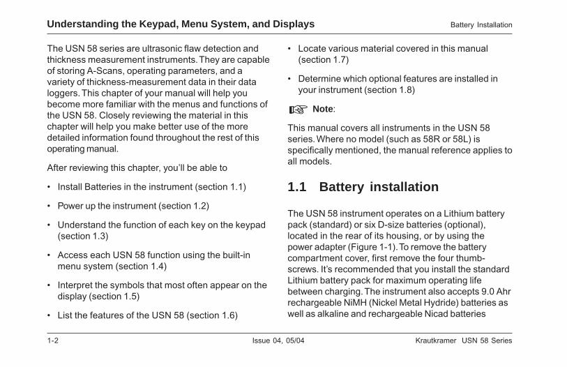
The USN 58 series are ultrasonic flaw detection andthickness measurement instruments. They are capableof storing A-Scans, operating parameters, and avariety of thickness-measurement data in their dataloggers. This chapter of your manual will help youbecome more familiar with the menus and functions ofthe USN 58. Closely reviewing the material in thischapter will help you make better use of the moredetailed information found throughout the rest of thisoperating manual.
After reviewing this chapter, you’ll be able to
• Install Batteries in the instrument (section 1.1)
• Power up the instrument (section 1.2)
• Understand the function of each key on the keypad(section 1.3)
• Access each USN 58 function using the built-inmenu system (section 1.4)
• Interpret the symbols that most often appear on thedisplay (section 1.5)
• List the features of the USN 58 (section 1.6)
• Locate various material covered in this manual(section 1.7)
• Determine which optional features are installed inyour instrument (section 1.8)
H Note:
This manual covers all instruments in the USN 58series. Where no model (such as 58R or 58L) isspecifically mentioned, the manual reference applies toall models.
1.1 Battery installation
The USN 58 instrument operates on a Lithium batterypack (standard) or six D-size batteries (optional),located in the rear of its housing, or by using thepower adapter (Figure 1-1). To remove the batterycompartment cover, first remove the four thumb-screws. It’s recommended that you install the standardLithium battery pack for maximum operating lifebetween charging. The instrument also accepts 9.0 Ahrrechargeable NiMH (Nickel Metal Hydride) batteries aswell as alkaline and rechargeable Nicad batteries
Understanding the Keypad, Menu System, and Displays Battery Installation

Krautkramer USN 58 Series Issue 04, 05/04 1-3
Krautkramer USN 58 Series Issue 04, 05/04 1-3
Battery Installation Understanding the Keypad, Menu System, and Displays
FIGURE 1-1—Installation of standard Lithium battery pack. Note the location ofthe Power Adapter Port and Lithium battery pack on-board charging port.
FIGURE 1-1—Installation of standard Lithium battery pack. Note the location ofthe Power Adapter Port and Lithium battery pack on-board charging port.
Battery Installation Understanding the Keypad, Menu System, and Displays

1-4 Issue 04, 05/04 Krautkramer USN 58 Series
1-4 Issue 04, 05/04 Krautkramer USN 58 Series
Understanding the Keypad, Menu System, and Displays Battery Installation
(optional battery tray is required). If D-cell batteries areused, be sure to follow the procedure explained insection 2.1 (Chapter 2, section 1) of this manual toensure your instrument is properly configured. Wheninstalling optional D-cell batteries, be sure to properlyalign the batteries’ poles as marked in the optionalbattery tray (required to install D-cells).
H Note:
Only the dedicated Krautkramer Lithium battery packcan be charged while installed in the instrument.Rechargeable D-cell batteries must be removed fromthe instrument for recharging.
The approximate level of remaining battery life is
visually displayed by the icon. The location of this
icon is shown in Figure 1-2. When a fully chargedbattery pack is installed, the icon will appear as “full.”As the battery life is consumed, the icon will begin to“empty.” Note that this indicator will only functioncorrectly if the correct battery type is selected asexplained in section 2.1 of this manual.
H Note:
When the battery indicator is in the last quarter as
indicated by the symbol , charge the battery pack as
soon as possible. The USN 58 automatically shuts offwhen batteries are too weak for reliable operation.Settings are saved and restored when the USN 58 isturned on again. When testing in remote locations,always carry spare batteries and/or battery pack.
H Note:
Your instrument was supplied with the standard Lithiumbattery pack. The Lithium Battery pack can be charged“on-board” and also power the instrument duringcharging. If you selected the optional D-cells andreceived a charger it should only be used for 9.0 AhrNiMH batteries.
H Note:
By connecting the optional Power Adapter, the USN 58can be operated using an AC power source. Thisadapter is connected to the instrument though thePower Adapter Port shown in Figure 1-1.

Krautkramer USN 58 Series Issue 04, 05/04 1-5
Krautkramer USN 58 Series Issue 04, 05/04 1-5
Powering On and Off the Instrument Understanding the Keypad, Menu System, and Displays
To charge the optional D-cell NiMH batteries you needonly remove the optional tray from the instrument,mate the tray to the charger, and plug the charger intoa 100-240 VAC power source. D-cell batteries cannotbe charged while the battery tray is connected to theinstrument. Refer to Appendix A for a completeexplanation of how to charge the batteries.
1.2 Powering On and Off theInstrument
Press and hold K for three seconds to power theinstrument on. Press K again to turn off.
1.3 Keypad and Knob Features
The USN 58 is designed to give the user quick accessto all of the instrument’s functions. It’s easy-to-usemenu system allows any function to be accessed withno more than three key presses (Figure 1-2). To accessany function:
• Press one of the six menu keys (u) to select amenu. The menus across the bottom of the displaywill immediately be replaced with the submenuscontained in the selected menu.
• Press a menu key (u) again to select the submenucontaining the desired function.
• Up to four functions will be displayed in the functionbar on the right side of the display. Select thedesired function, by pressing one of the four functionkeys (v).
• Change the value listed in the function box with thefunction knob. Some values can also be adjustedwith repeated presses of the function key.
You’ll also find these keys and knobs on theinstrument (The 58R is shown in Figure 1-2A, the 58Lis shown in Figure 1-2B):
X—Test Menu Key switches from the Home Menu tothe Test Menu. A second press displays the gridmarkers in the menu bar, a third press activates a baridentifying display delay and range, and a fourth pressreturns to the original menu position.
h—Home Keys immediately return the instrumentto the Home Menu.
Powering On and Off the Instrument Understanding the Keypad, Menu System, and Displays

1-6 Issue 04, 05/04 Krautkramer USN 58 Series
1-6 Issue 04, 05/04 Krautkramer USN 58 Series
Understanding the Keypad, Menu System, and Displays Keypad and Knob Features
FIGURE 1-2A—Some of the USN 58R keypad and knob functions are shown here.
FIGURE 1-2A—Some of the USN 58R keypad and knob functions are shown here.
Understanding the Keypad, Menu System, and Displays Keypad and Knob Features
Krautkramer USN 58 Series Issue 04, 05/04 1-7
Krautkramer USN 58 Series Issue 04, 05/04 1-7
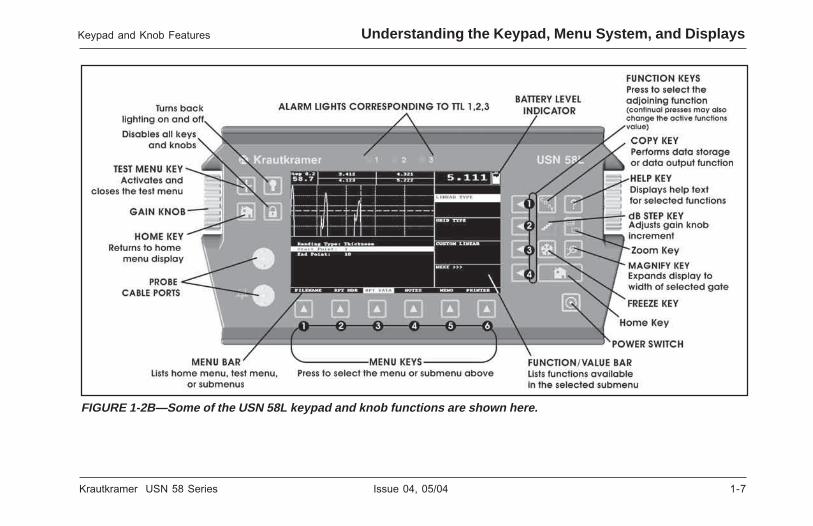
FIGURE 1-2B—Some of the USN 58L keypad and knob functions are shown here.
FIGURE 1-2B—Some of the USN 58L keypad and knob functions are shown here.
Keypad and Knob Features Understanding the Keypad, Menu System, and Displays
Keypad and Knob Features Understanding the Keypad, Menu System, and Displays

1-8 Issue 04, 05/04 Krautkramer USN 58 Series
1-8 Issue 04, 05/04 Krautkramer USN 58 Series
USN 58 Menus and Functions Understanding the Keypad, Menu System, and Displays
?—Help Key displays help screen text describingthose functions displayed in the Function Bar.
W—Freeze Key freezes the A-Scan display in one offour user-defined modes.
C—Copy Key performs a data-storage or data-outputfunction depending on the user-defined mode. Forinstance, sends a thickness measurement to the nextavailable position in an active data logger file.
K—Power Key turns the instrument on and off.
L—Zoom Key displays A-Scan on the entire screen.
H—Magnify Key enlarges A-Scan display to set thewidth of the magnified gate to full-screen width.
D—dB Step Key changes the adjustment increment ofthe gain knob.
—Backlite Key turns display back lighting on and off(58L only).
—Lock Key disables the Function and Gain rotaryknobs (58L only).
Function Rotary Knob - Rotate to change thevalue of the selected function.
Gain Rotary Knob - Rotate to change theinstrument’s gain.
1.4 USN 58 Menus and Functions
The USN 58 menu system allows the operator toselect and adjust various features and instrumentsettings. It includes:
Home Menu—Several menus used to configure andcalibrate the instrument prior to test. Also used toselect pulser and receiver characteristics, positiongates, set alarms, specify operating mode and screenappearance, adjust the A-Scan display, and controlother significant measurement features
Test Menu—Allows the operator to make thoseadjustments that are most often required during thetesting process
H Note:
Figures 1-3 and 1-4 show the instrument’s Home andTest Menu structures. The information provided in thefollowing two manual sections explains what eachfunction does and shows how to access the function
?—Help Key displays help screen text describingthose functions displayed in the Function Bar.
W—Freeze Key freezes the A-Scan display in one offour user-defined modes.
C—Copy Key performs a data-storage or data-outputfunction depending on the user-defined mode. Forinstance, sends a thickness measurement to the nextavailable position in an active data logger file.
K—Power Key turns the instrument on and off.
L—Zoom Key displays A-Scan on the entire screen.
H—Magnify Key enlarges A-Scan display to set thewidth of the magnified gate to full-screen width.
D—dB Step Key changes the adjustment increment ofthe gain knob.
—Backlite Key turns display back lighting on andoff.
—Lock Key disables the Function and Gain rotaryknobs.
Function Rotary Knob - Rotate to change thevalue of the selected function.
Gain Rotary Knob - Rotate to change theinstrument’s gain.
1.4 USN 58 Menus and Functions
The USN 58 menu system allows the operator toselect and adjust various features and instrumentsettings. It includes:
Home Menu—Several menus used to configure andcalibrate the instrument prior to test. Also used toselect pulser and receiver characteristics, positiongates, set alarms, specify operating mode and screenappearance, adjust the A-Scan display, and controlother significant measurement features
Test Menu—Allows the operator to make thoseadjustments that are most often required during thetesting process
H Note:
Figures 1-3 and 1-4 show the instrument’s Home andTest Menu structures. The information provided in thefollowing two manual sections explains what eachfunction does and shows how to access the function
USN 58 Menus and Functions Understanding the Keypad, Menu System, and Displays

Krautkramer USN 58 Series Issue 04, 05/04 1-9
Krautkramer USN 58 Series Issue 04, 05/04 1-9
Understanding the Keypad, Menu System, and Displays USN 58 Menus and Functions
through the menu system. You’ll also find operation-manual section references that tell you where to turn inthis manual for more specific information on eachfunction.
1.4.1 Home Menu System
The USN 58‘s Home Menu System consists of severalmenus, submenus, and functions.
• Available menus are accessed via the Home Menu(The 58R home menu is shown in Figure 1-3A. The58L home menu is shown in Figure 1-3B). Note thatthe menus visible on your particular instrumentdepend on which options are installed. Functions notshown in Figure 1-3 are accessed by pressing ubelow the option NEXT.
• Each menu contains several submenus.
• Menus and submenus are selected by pressingbelow the desired item.
• When a submenu is selected, the functionscontained in that submenu are listed in the FunctionBar down the right-hand side of the display screen.
• Functions are then selected by pressing theadjacent Function Key (v).
• Turning the Function Knob, and in some casescontinuing to press v, will change the value shownin the selected function’s box.
Note that some functions, like RANGE, have bothcoarse and fine adjustment modes. Coarse and finemodes are selected by pressing v more than once.When the function name, such as RANGE, appears inall capital letters, turning the function knob will producelarge changes in the selected function’s value. Whenthe function name appears in all lower-case letters,turning the function knob will change the value bysmaller amounts. Functions with coarse-and-fineadjustment capabilities are noted with an * inFigure 1-3.
Understanding the Keypad, Menu System, and Displays USN 58 Menus and Functions

1-10 Issue 04, 05/04 Krautkramer USN 58 Series
1-10 Issue 04, 05/04 Krautkramer USN 58 Series
USN 58 Menus and Functions Understanding the Keypad, Menu System, and Displays
USN 58 Menus and Functions Understanding the Keypad, Menu System, and Displays
FIGURE 1-3A—These USN 58R menus, submenus, and functions are accessed through the Home Menu.
FIGURE 1-3A—These USN 58R menus, submenus, and functions are accessed through the Home Menu.

Krautkramer USN 58 Series Issue 04, 05/04 1-11
Krautkramer USN 58 Series Issue 04, 05/04 1-11
FIGURE 1-3B—These USN 58L menus, submenus, and functions are accessed through the Home Menu.
FIGURE 1-3B—These USN 58L menus, submenus, and functions are accessed through the Home Menu.
USN 58 Menus and Functions Understanding the Keypad, Menu System, and Displays
USN 58 Menus and Functions Understanding the Keypad, Menu System, and Displays

1-12 Issue 04, 05/04 Krautkramer USN 58 Series
1-12 Issue 04, 05/04 Krautkramer USN 58 Series
BASIC Menu
RANGE Submenu• RANGE—Adjusts the range of the display screen from .040"
to 480" in steel. (Refer to section 2.3.1)
• PROBE DELAY—Represents the time delay caused by
sound-wave travel through a probe’s wearplate, membrane,
delay line, or wedge. (Refer to section 2.3.3)
• VELOCITY—Displays the velocity for the selected material
and allows the user to input a velocity. (Refer to section 2.3.3)
• DISPLAY DELAY—Shifts the A-Scan viewing window to the
left or right. (Refer to section 2.3.2)
CONFIG Submenu• MATERIAL—Selects the material being tested. Choose
designations with “S” (shear) for angle beam probes. Sets
velocity to value for material specified. (Refer to section 2.3)
• DISPLAY START—Sets the reference point from which all
display features are set. (Refer to section 2.3.3)
• A-SCAN MODE—Changes the appearance of the A-Scan
(Refer to 2.1.2) and launches SMART VIEW (Refer to 6.2)
• A-SCAN ENHANCE—Enables the BASELINE BREAK and
SPARKLE (58L) display features (Refer to section 6.3)
DISPLAY Submenu (Refer to section 2.1.2)
• COLOR—Changes the colors of the display (58L)
• BRIGHTNESS—Adjusts the display’s brightness
• GRID—Selects the display screen’s grid markings.
• A-Scan Color—Adjusts the color of the A-Scan (58L)
• ReverseVideo—Select normal or reversed video display (58R)
REGIONAL Submenu (Refer to section 2.1.1)
• LANGUAGE—Sets the language displayed on the instrument’s
screen
• UNITS—Sets displayed units to inch, millimeter, or microsecond
• DATE—Sets the displayed date
• TIME—Sets the displayed time
OPTIONS Submenu• INSTALLED OPTION—Use to identify installed options (Refer
to 1.9.2)
• FREEZE MODE—Determines what is frozen when the Freeze
Key is pressed. (Refer to section 3.3)
• BATTERY TYPE—Specify the type installed (Refer to 2.1)
• MASTER LOCK—Turning Lock on disables all functions
except Gain (Refer to section 3.7)
RESULTS Submenu• READING 1 THROUGH READING 4-Selects the
measurement displayed in each of the four Reading Boxes.
(Refer to section 3.5)
PLSRCVR Menu
PULSER Submenu
• PULSER TYPE—Select square (58L) or spike pulse (2.3.6)
• ENERGY—Sets energy level of spike pulse (Refer to 2.3.7)
• VOLTAGE—Sets pulser (square only–available only in 58L)
voltage level (Refer to 2.3.7)
Understanding the Keypad, Menu System, and Displays USN 58 Menus and Functions
Understanding the Keypad, Menu System, and Displays USN 58 Menus and Functions
BASIC Menu
RANGE Submenu• RANGE—Adjusts the range of the display screen from .040"
to 480" in steel. (Refer to section 2.3.1)
• PROBE DELAY—Represents the time delay caused by
sound-wave travel through a probe’s wearplate, membrane,
delay line, or wedge. (Refer to section 2.3.3)
• VELOCITY—Displays the velocity for the selected material
and allows the user to input a velocity. (Refer to section 2.3.3)
• DISPLAY DELAY—Shifts the A-Scan viewing window to the
left or right. (Refer to section 2.3.2)
CONFIG Submenu• MATERIAL—Selects the material being tested. Choose
designations with “S” (shear) for angle beam probes. Sets
velocity to value for material specified. (Refer to section 2.3)
• DISPLAY START—Sets the reference point from which all
display features are set. (Refer to section 2.3.3)
• A-SCAN MODE—Changes the appearance of the A-Scan
(Refer to 2.1.2) and launches SMART VIEW (Refer to 6.2)
• A-SCAN ENHANCE—Enables the BASELINE BREAK and
SPARKLE (58L) display features (Refer to section 6.3)
DISPLAY Submenu (Refer to section 2.1.2)
• COLOR—Changes the colors of the display (58L)
• BRIGHTNESS—Adjusts the display’s brightness
• GRID—Selects the display screen’s grid markings.
• A-Scan Color—Adjusts the color of the A-Scan (58L)
• ReverseVideo—Select normal or reversed video display (58R)
REGIONAL Submenu (Refer to section 2.1.1)
• LANGUAGE—Sets the language displayed on the instrument’s
screen
• UNITS—Sets displayed units to inch, millimeter, or microsecond
• DATE—Sets the displayed date
• TIME—Sets the displayed time
OPTIONS Submenu• INSTALLED OPTION—Use to identify installed options (Refer
to 1.9.2)
• FREEZE MODE—Determines what is frozen when the Freeze
Key is pressed. (Refer to section 3.3)
• BATTERY TYPE—Specify the type installed (Refer to 2.1)
• MASTER LOCK—Turning Lock on disables all functions
except Gain (Refer to section 3.7)
RESULTS Submenu• READING 1 THROUGH READING 4-Selects the
measurement displayed in each of the four Reading Boxes.
(Refer to section 3.5)
PLSRCVR Menu
PULSER Submenu
• PULSER TYPE—Select square (58L) or spike pulse (2.3.6)
• ENERGY—Sets energy level of spike pulse (Refer to 2.3.7)
• VOLTAGE—Sets pulser (square only–available only in 58L)
voltage level (Refer to 2.3.7)

Krautkramer USN 58 Series Issue 04, 05/04 1-13
Krautkramer USN 58 Series Issue 04, 05/04 1-13
• WIDTH—Sets width of square pulse (58L) (section 2.3.8)
• DAMPING—Adjusts the damping level to match the installed
probe. (Refer to section 2.2.2)
RECEIVER Submenu• FREQUENCY—Selects the bandwidth of the instrument.
(Refer to section 2.2.2)
• RECTIFY—Selects the rectification-mode which effects how
the A-Scan appears on the display. (Refer to section 2.3.5)
• DUAL—Identifies whether one or two single-element probes,
or a dual element probe, is installed (Refer to section 2.2.2)
• REJECT—Determines what percentage of the A-Scan height
is displayed at 0% full screen height. (Refer to section 2.3.7)
GAIN Submenu• USER GAIN STEP—Specify a gain value to appear in the Test
Menu’s dB Step selections. (Refer to section 4.2.2)
• dB REF—Stores reference gain value and echo height. (Refer
to 4.3)
• AMPLITUDE—Sets the units of amplitude measurement to
percentage of screen height or dB difference in height from
the gate to the echo’s peak. (Refer to section 3.1.6)
• dB Step—Defines increment of gain-value change when knob
is turned. (Refer to section 4.2)
PRF Submenu• MODE—Selects the mode by which the Pulse Repetition
Frequency is determined. (Refer to section 2.3.4)
• VALUE—Displays and/or allows adjustment of the Pulse
Repetition Frequency. (Refer to section 2.3.4)
GATES Menu
POSITION Submenu (Refer to section 3.1.1)
• GATE SELECT—Select from two or more gates (depending
on the installed options).
• GATE START—Sets the beginning position of the selected
gate on the A-Scan.
• GATE WIDTH—Sets the width of the selected gate on the
A-Scan.
• GATE THRESHOLD—Sets the height of the selected gate.
GATEMODE Submenu• GATE SELECT—Select from two or more gates (depends on
the installed options). (Refer to section 3.1.2)
• DETECTION—Indicates whether an A-Scan echo’s flank, or
peak is evaluated by the gate. (Refer to section 3.1.2)
• START MODE—Set to IP (initial pulse) in base-model USN 58.
• MAGNIFY GATE—Allows the user to select which gate is
magnified to ful screen width when H is pressed (depends on
the installed options). (Refer to section 3.1.3)
ALARMS Submenu (Refer to 3.1.4)
• GATE SELECT—Select from two or more gates (depends on
the installed options).
• LOGIC—Determines whether the gate alarm is triggered
when a signal crosses the gate or does not cross the gate.
USN 58 Menus and Functions Understanding the Keypad, Menu System, and Displays

1-14 Issue 04, 05/04 Krautkramer USN 58 Series
1-14 Issue 04, 05/04 Krautkramer USN 58 Series
• OUTPUT DELAY—Delays TTL and Analog Outputs.
(Refer to section 7.2)
• HORN—Enables the audible warning alarm (horn).
TTL OUT Submenu• TTL #1—Identifies which event triggers TTL 1 / illuminates
Warning Light 1. (Refer to section 3.1.4)
• TTL #2—Identifies which event triggers TTL 2 / illuminates
Warning Light 2. (Refer to section 3.1.4)
• TTL #3—Identifies which event triggers TTL 3 / illuminates
Warning Light 2. (Refer to section 3.1.4)
• MODE—Specifies how the TTL Alarms are reset. (Refer to
section 3.1.5)
LIMITS Submenu (Refer to section 3.2)
• LOW LIMIT—Use to set the minimum thickness for alarm
purposes.
• HIGH LIMIT—Use to set the maximum thickness for alarm
purposes.
NOISE IMMN Submenu (Refer to section 6.1)
• GATE SELECT—Select from two or more gates (depending
on installed options).
• COUNT—Specify the number of alarm-violating counts which
must occur during the WINDOW duration before an alarm is
set.
• WINDOW—Specify the number of counts in the examination
period.
AUTOCAL Menu
SETUP Submenu (Refer to section 2.4)
• GATE A START—Shifts the starting point of the A-Gate to the
left and right.
• S-REF 1-User—input thickness value of the thinner calibration
standard.
• S-REF 2-User—input thickness value of the thicker calibration
standard.
• RECORD—Identifies and progresses through each stage of
the calibration procedure.
READING Submenu (Refer to section 2.4.3)• VELOCITY—Display’s the instrument’s default velocity for the
specified material type as well as the calculated velocity after
calibration.
• PROBE DELAY—Adjustment made as a result of the zeroing
procedure. This represents the time delay caused by sound-
wave travel through a probe’s wearplate, membrane, delay
line, or wedge (plastic).
FILES Menu
FILENAME Submenu• FILENAME—Selects stored files. (Refer to section 5.3)
• PREVIEW—Use to view the header and memo of stored files
without recalling the file. (Refer to section 5.3)
• ACTION—Recalls or deletes the selected file and saves edits
to alphanumeric and parameter settings. (Refer to 5.3 and 5.4)
Understanding the Keypad, Menu System, and Displays USN 58 Menus and Functions

Krautkramer USN 58 Series Issue 04, 05/04 1-15
Krautkramer USN 58 Series Issue 04, 05/04 1-15
• CREATE NEW—Pressing twice launches the file creation
process. (Refer to section 5.1)
REP HEAD Submenu• HEADER NUMBER—Selects the Header Line to edit. (Refer
to section 5.6)
• EDIT—Allows editing of the selected Header Line contents.
(Refer to section 5.6)
• PRINT ?—Determines if the header will be included in the
printed report. (Refer to section 5.6.1)
NOTES Submenu• NOTE NUMBER—Selects the Note Line to edit. (Refer to
section 5.7)
• EDIT—Allows editing of the selected Note Line contents.
(Refer to section 5.7)
• NOTE PRINT ?—Determines if the notes will be included in
the printed report. (Refer to section 5.7.1)
• DL PRINT—Determines if the data logger thickness
measurements will be included in the printed report. (Refer to
section 5.8)
MEMO Submenu• EDIT—Allows editing / creation of the Memo. (Refer to 5.5)
• PRINT ?—Determines if the memo will be included in the
printed report. (Refer to section 5.5.1)
PRINTER Submenu• PRINTER—Use to select the type of printer connected. (Refer
to section 5.9.1)
• COPY MODE—Specifies the action taken by pressing the
Copy key. (Refer to section 5.9.2)
• PARAM PRINT ?—Determines if instrument settings will be
listed in the printed report. (Refer to section 5.8)
• A-SCAN PRINT ?—Determines if the A-Scan will be included
in the printed report. (Refer to section 5.8)
General Submenu• DL DATA Function—Displays stored datalogger values and
attached notes.
TRIG Menu
SETUP Submenu (Refer to section 3.4)
• PROBE ANGLE—Input the angle of a connected angle beam
probe.
• THICKNESS—Sets the test-piece material thickness for
angle-beam measurements.
• X VALUE—Input the specified value from the angle beam
probe’s BIP to front edge.
• O-DIAMETER—Sets the outside diameter of curved test
pieces.
AWS D1.1 Submenu (Refer to section 6.4)
• A INDICATION—Gain representation of test-piece reflector.
• B REFERENCE—Gain representation of reference reflector.
• C ATTENUATION—Calculated Gain representation of depth
variation between reference and test-piece reflector.
USN 58 Menus and Functions Understanding the Keypad, Menu System, and Displays

1-16 Issue 04, 05/04 Krautkramer USN 58 Series
1-16 Issue 04, 05/04 Krautkramer USN 58 Series
• D D1.1 RATING—Calculated weld rating for measured test
piece.
A POS Submenu (Refer to section 6.4)
• GATE A START—Sets A-Gate starting point.
• GATE WIDTH—Sets width of the A-Gate.
• A THRESHOLD—Sets A-Gate’s height.
• AWS MODE—Turned on manually or automatically with a
stored reference.
COLORING Submenu (58L) (Refer to section 3.5)
• COLOR LEG—Indicates in which leg a reflector is located.
(Used with angle beam probes.)
SERIAL COMM Menu
• BAUD RATE—Set to match the connected printer. (Refer to
section 5.10.1)
• LOSS OF SIGNAL—Controls the thickness value and analog
signal outputted when an uncoupled probe condition exists.
(Refer to section 5.10.2)
1.4.2 Test Menus and Functions
The USN 58 also has a Test Menu that’s displayedwhenever X is pressed. This menu contains the
control capabilities most commonly used while testingmaterial. The Test Menu features, and their functionsare shown in Figure 1-4. While a USN 58R is shown,test menu features and keypad functions are the samefor all USN 58 series instruments. Note that thefunction bar displayed when X is pressed continues tobe displayed when the Test Menu is active. PressingX three more times returns to the previous menuconfiguration.
1.5 Display Screen Features
The USN 58‘s displays are designed to be easy tointerpret. In Figure 1-5 you’ll find an example of the adisplay configuration. This specific display includes adata logger file navigation window (which allows you tonavigate through and store thickness measurements inan existing data logger file), an active A-Scan, theGATES menu bar, and POSITION submenu. Refer tothis Figure for an explanation of those screen featuresyou’ll most often encounter. You’ll also find a referenceto the manual section which explains the identifiedfeature in more depth.
Understanding the Keypad, Menu System, and Displays Display Screen Features
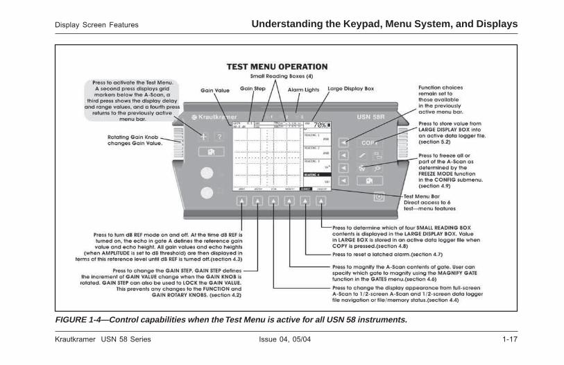
Krautkramer USN 58 Series Issue 04, 05/04 1-17
Krautkramer USN 58 Series Issue 04, 05/04 1-17
Display Screen Features Understanding the Keypad, Menu System, and Displays
FIGURE 1-4—Control capabilities when the Test Menu is active for all USN 58 instruments.
FIGURE 1-4—Control capabilities when the Test Menu is active for all USN 58 instruments.
Display Screen Features Understanding the Keypad, Menu System, and Displays
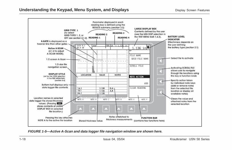
1-18 Issue 04, 05/04 Krautkramer USN 58 Series
1-18 Issue 04, 05/04 Krautkramer USN 58 Series
Understanding the Keypad, Menu System, and Displays Display Screen Features
FIGURE 1-5—Active A-Scan and data logger file navigation window are shown here.
FIGURE 1-5—Active A-Scan and data logger file navigation window are shown here.
Understanding the Keypad, Menu System, and Displays Display Screen Features

Krautkramer USN 58 Series Issue 04, 05/04 1-19
Krautkramer USN 58 Series Issue 04, 05/04 1-19
Definition of Display Icons
There are several graphical features (icons) whichappear in the display screen’s icon bar for variousreasons. Figure 1-6 includes several of these iconsalong with an explanation of their significance.
1.6 Features of the USN 58
The USN 58 series extends the performance and rangeof applications that are capable of being satisfied by aportable instrument. The quality, portability, durability,& dependability that you have come to expect from thepopular Krautkramer USN Series of instrumentsremains.
• The USN 58R has a hi-resolution (320 x 240 pixels)EL Display with 60 Hz update
• The 58L is equipped with a 400 x 240 pixel colordisplay that also updates at 60 Hz
• Simple operation with fast rotary knob adjustments
• Weighs only 6.4 lbs. including Lithium battery packor optional D-size batteries for convenient useanywhere
• Two independent flaw gates with real-time TTL &Analog Outputs to handle a wide range ofapplications (plus a third optional Interface gate)
• 250 kHz to 25 MHz capability with eight selectablefrequency ranges to match probe for optimumperformance
Features of USN 58R Understanding the Keypad, Menu System, and Displays
FIGURE 1-6—These icons appear in the Status Bar atvarious times.
Definition of Display Icons
There are several graphical features (icons) whichappear in the display screen’s icon bar for variousreasons. Figure 1-6 includes several of these iconsalong with an explanation of their significance.
1.6 Features of the USN 58
The USN 58 series extends the performance and rangeof applications that are capable of being satisfied by aportable instrument. The quality, portability, durability,& dependability that you have come to expect from thepopular Krautkramer USN Series of instrumentsremains.
• The USN 58R has a hi-resolution (320 x 240 pixels)EL Display with 60 Hz update
• The 58L is equipped with a 400 x 240 pixel colordisplay that also updates at 60 Hz
• Simple operation with fast rotary knob adjustments
• Weighs only 6.4 lbs. including Lithium battery packor optional D-size batteries for convenient useanywhere
• Two independent flaw gates with real-time TTL &Analog Outputs to handle a wide range ofapplications (plus a third optional Interface gate)
• 250 kHz to 25 MHz capability with eight selectablefrequency ranges to match probe for optimumperformance
FIGURE 1-6—These icons appear in the Status Bar atvarious times.
Features of USN 58R Understanding the Keypad, Menu System, and Displays

1-20 Issue 04, 05/04 Krautkramer USN 58 Series
1-20 Issue 04, 05/04 Krautkramer USN 58 Series
• 15 Hz PRF (pulse repetition frequency) with 480"range in steel eliminates “ghost echoes” making itideal for lengthy acoustically clean material testing
• Smart View function displays the most importantinformation (relevant shot) for the test as selectedby the user
• Compare frozen reference waveforms to live A-Scans
• Alphanumeric Datalogger (incl. Grid file format) forflexible, convenient storage of data sets andthickness readings
• Multiple curve DAC/TCG corrects for distance/amplitude variations from material loss and beamspread
• Eight hours of use between charges with thestandard Lithium battery pack
• Four hours of use (typical) with optional D-size 9.0Ahr NiMH. (power adapter for bench-top use)
• Four selectable damping settings (50, 75, 150, &500 ohms) for optimum probe performance
• Trig functions to automatically determine depth,surface distance, sound path to flaws, and leg of theinspection using shear-wave (angle beam) probes
• RF rectification for phase inversion and thinmeasurement applications
• Auto CAL makes calibration simple & easy
• .040" minimum range (in steel) for thin measurementapplications
• Help mode with dedicated key on front panel forquick access
• dB Step function with six gain knob increments
• Thickness data logger with alphanumeric naming oflocation I.D.’s, grid file format, notes and memocapabilities
• Store, preview, and edit data sets with A-Scans forquick recall and instrument setup
• Noise Immunization feature limits the effect of falseTTL outputs due to high noise levels
Understanding the Keypad, Menu System, and Displays Features of USN 58R

Krautkramer USN 58 Series Issue 04, 05/04 1-21
Krautkramer USN 58 Series Issue 04, 05/04 1-21
• Special “behind the freeze” mode allows dynamictime-base adjustment on frozen A-Scan displays
• Versatile, flexible carry bag with neck strap for easytransport and use in limited access areas
• Upgrade CD is provided with each instrument toeasily upgrade the Operating Software via ourwebsite without returning the instrument to addfeatures and capabilities without downtime
1.7 What’s in this Manual
The USN 58 Series Operating Manual is divided intoseveral chapters. The material in Chapters 1 through 7applies to all instrument models. Chapter 8 and higherapply only to optional features which are available onlywhen purchased. Following is a summary of Chapters 1through 7:
Chapter 1—Understanding the Keypad, MenuSystem, and Displays
Operations performed Explanation of displayby each key features
Navigating the menus Summary of features
Overview of functions Definition of iconswithin menus
How the instrument detectsflaws and measures thickness
Chapter 2—Setting Up the USN 58
Set up the instrument Calibrate the instrument/display appearance probe combination
Install a probe andconfigure the instrumentto match the probe type
Chapter 3—Configuring Your Instrument forMeasurement
Adjust the A and Specify gate-detectionB-Gates mode (peak or flank)
Set and clear alarms Control the A-Scan magnifyand TTL outputs and freeze modes
Select the maximum Specify the quantitiesand minimum material displayed in the data read-thickness limits ing boxes
What’s in this Manual Understanding the Keypad, Menu System, and Displays

1-22 Issue 04, 05/04 Krautkramer USN 58 Series
1-22 Issue 04, 05/04 Krautkramer USN 58 Series
Chapter 4—Using the Test Menu
Use the dB Access the file navigationREFERENCE window using the viewfeature to compare the featurecurrent echo’s amplitudewith a reference
Magnify the contents Attach Notes to storedof a selected gate readings
Freeze and unfreeze Access the help screenthe A-Scan display
Select the value to viewin the large display box andcopied to active data loggerfile position
Chapter 5—Storing and Outputting Data
Differentiate between List of those parametersdata logger and data settings stored in dataset files set or data logger files
Create, store, recall, Printing Reportsand delete data files
Modify and attach Modify and attach notes tomemos and report a stored data pointheaders to a data file
Configuring the instrumentto communicate withexternal printers.
Chapter 6—Advanced Settings for Base-ModelUnits
Use the Noise Operate in SMART ViewImmunization Feature Mode
Reset the instrumentusing key presses
Chapter 7— I/O Ports Technical Details
Analog Output Remote Control
Chapter 8—DAC/TCG Option
Chapter 9—IF Gate Option
Chapter 10—DGS Option
Chapter 11—BEA (Backwall Echo Attenuator) Option
Chapter 12—VGA Connector Option
Understanding the Keypad, Menu System, and Displays What’s in this Manual

Krautkramer USN 58 Series Issue 04, 05/04 1-23
Krautkramer USN 58 Series Issue 04, 05/04 1-23
1.8 Overview of OptionalFeatures
Several options are available to be added to base-model USN 58 instruments. Options purchased withyour instrument will be described in detail later in thismanual. This section explains how to tell which optionsare installed in your instrument and includes a briefoverview of the features available with each option.Any USN 58R instrument can be retrofitted withavailable options.
1.8.1 Determing Which Optional Featuresare Installed in Your USN 58(Basic/Options/Installed Option)
In the BASIC MENU, select the OPTIONS submenu.Select the INSTALLED OPTION function and turn theFunction Knob to view those options installed in yourinstrument. Selections include BASIC, plus thoseoptions listed below which have been installed in yourparticular instrument:
• DAC/TCG—The DAC (Distance Amplitude Curve)feature allows the user to collect up to 16 same-size-reflector echoes, representing various materialdepths, and generate a curve that fits the echopeaks. In this mode all echoes are represented attheir true amplitude with no depth or attenuationcompensation. Three additional curves, drawn atuser-specified dB offsets from the original DACcurve, can be displayed at one time. The TCG (TimeCorrected Gain) feature allows all equivalent echoesto be displayed at the same height, regardless ofmaterial depth related signal loss (caused byattenuation and beam spread). TCG works byadjusting gain over time to ensure that like-reflectors, located at different material depths, arerepresented by same-amplitude echoes.
• Distance Gain Size—The DGS feature allows theuser to display a curve which represents equivalent-reflector-sizes, for a particular gain, as a function ofthe distance between the reflector and transducer.DGS assumes a vertical beam impingement. Flawsizing evaluations can be done via dB to the DGScurve or ERS (Equivalent Reflector Size) methods.
Overview of Optional Features Understanding the Keypad, Menu System, and Displays
1-24 Issue 04, 05/04 Krautkramer USN 58 Series
1-24 Issue 04, 05/04 Krautkramer USN 58 Series
• IF Gate—Monitors the time window from the initialpulse to the interface between two materials, wherethe top material is ignored and timing begins at theinterface to make measurements in the secondmaterial. Typically used for immersion testing, tobegin measurements at the interface between waterand the top of the material to be inspected.
• Backwall Echo Attenuator—The BEA feature allowsthe user to monitor the backwall echo by amplifyingthe region under Gate B by the amount specified bythe backwall gain control.
1.8.2 How Options are Dealt with in ThisManual
When an option is installed, several additionalfunctions and, in some cases submenus, are available.These additional capabilities can only be accessedwhen the option is installed. Whenever these specialfeatures are discussed in this manual, they will beidentified as being available only with one or more ofthe optional upgrades. If no reference to an optionalupgrade is made, assume that the feature is availablewith the base-model instrument.
Understanding the Keypad, Menu System, and Displays Overview of Optional Features

Krautkramer USN 58 Series Issue 04, 05/04 2-1
Krautkramer USN 58 Series Issue 04, 05/04 2-1
Setup and Calibrationof the USN 58 2
Setup and Calibrationof the USN 58 2

2-2 Issue 04, 05/04 Krautkramer USN 58 Series
2-2 Issue 04, 05/04 Krautkramer USN 58 Series
Setup and Calibration of the USN 58 Initial Instrument Setup
This chapter explains how to prepare your instrumentfor use. In this chapter, you’ll learn how to
• Set up the instrument’s display and basic operatingfeatures (section 2.1)
• Install a probe and configure the Pulser/Receiver tomatch the probe type (section 2.2)
• Adjusting the A-Scan display screen’s appearance(section 2.3)
• Calibrate the instrument (section 2.4)
Most sections in this chapter describe steps that willbe followed by every user of a new instrument. For thisreason, we suggest that you proceed through eachsection in this chapter while configuring yourinstrument for the first time.
2.1 Initial Instrument Setup
In this part of the manual, you’ll learn how to configurethe USN 58’s display and operating features. Followthese procedures to turn on the USN 58 and makeinitial adjustments to the instrument control settings.
Because the USN 58 saves the control settings whenit’s turned off and restores them when it’s turned on,you won’t have to repeat these adjustments unless achange is required.
Turn on the USN 58 by pressing K. The Home Menuwill be activated. This menu’s structure was shown inFigures 1-3A and B. Activate the Basic Menu bypressing u below it. Some submenus and functionsfrom the Basic Menu are shown in Figure 2-1.
Specifying the Installed Battery Type(BASIC-OPTIONS-BATTERY TYPE)
H Note:
Selection of battery type only affects the accuracy ofthe on-screen battery-indicator. This ensures properindication of remaining power.
Step 1: Activate the OPTIONS submenu (located inthe Basic Menu) by pressing u below it. Fourfunctions will appear down the right side of the displayscreen.
Step 2: Press v next to the selection titled BATTERYTYPE. To change the selected battery type, continuepressing v or turn the function knob. You’ll note that
Setup and Calibration of the USN 58 Initial Instrument Setup

Krautkramer USN 58 Series Issue 04, 05/04 2-3
Krautkramer USN 58 Series Issue 04, 05/04 2-3
Initial Instrument Setup Setup and Calibration of the USN 58
FIGURE 2-1—The Basic Menu allows the user to adjust most of the instrument’s display and operating features.
FIGURE 2-1—The Basic Menu allows the user to adjust most of the instrument’s display and operating features.
Initial Instrument Setup Setup and Calibration of the USN 58

2-4 Issue 04, 05/04 Krautkramer USN 58 Series
2-4 Issue 04, 05/04 Krautkramer USN 58 Series
Setup and Calibration of the USN 58 Initial Instrument Setup
the options available are Lithium, NiMH (nickel metalhydride), NiCAD, and Alkaline. The default battery typeis Lithium.
Step 3: Setting the correct battery type ensuresaccurate battery indicator levels.
2.1.1 Regional Settings-Language, Unitsof Measurement, Date, and Time
Use the procedures below to adjust the unit ofmeasurement, the date, the time, and the languagethat appears on the instrument’s display screens anddata output. The adjustments will require access to theREGIONAL submenu. This is accessed from the BasicMenu (shown in Figure 2-1).
Setting the Operating Language(BASIC-REGIONAL-LANGUAGE)
Step 1: Activate the REGIONAL submenu (located inthe Basic Menu) by pressing u below it. Fourfunctions will appear down the right side of the displayscreen.
Step 2: Press v next to the selection titledLANGUAGE. To change the selected language,
continue pressing v or turn the function knob. You’llnote that the options available are English, German,French, Spanish, Italian, Portuguese, Norwegian,Swedish, Finnish, Danish, Czech, Romanian,Slovenian, and Russian. The default language isEnglish.
Step 3: The display-screen and report language will beset to the choice last selected.
Setting the Date(BASIC-REGIONAL-DATE)
Step 1: Activate the REGIONAL submenu (located in theBasic Menu) by pressing u below it. Four functions willappear down the right side of the display screen.
Step 2: Press v next to the selection titled DATE. Thedate is displayed in Day/Month/Year format. Note thatthe first time you press v, the day character ishighlighted. The next time you press v, the monthcharacter is highlighted. Finally, pressing v again willcause the year character to be highlighted.
Step 3: To change the month, days, or year, turn thefunction knob while the desired character ishighlighted.
Setup and Calibration of the USN 58 Initial Instrument Setup

Krautkramer USN 58 Series Issue 04, 05/04 2-5
Krautkramer USN 58 Series Issue 04, 05/04 2-5
Initial Instrument Setup Setup and Calibration of the USN 58
Step 4: When complete, press v one more time. Thecurrent date will be set to the date displayed.
Setting the Time (BASIC-REGIONAL-TIME)
Step 1: Activate the REGIONAL submenu (located inthe Basic Menu) by pressing u below it. Fourfunctions will appear down the right side of the displayscreen.
Step 2: Press v next to the selection titled TIME.Time is displayed in 24-hour format. Note that the firsttime you press v, the hours character is highlighted.The next time you press v, the minutes character ishighlighted. Finally, pressing v again will cause theseconds character to be highlighted.
Step 3: To change the hours, minutes, or secondssetting, turn the function knob while the desiredcharacter is highlighted.
Step 4: When complete, press v one more time. Thecurrent time will be set to the time displayed.
H Note:
Once set, the internal clock of the USN 58 willmaintain the current date and time.
Setting the Units of Measurement(BASIC-REGIONAL-UNITS)
Step 1: Activate the REGIONAL submenu (located inthe Basic Menu) by pressing u below it. Fourfunctions will appear down the right side of the displayscreen.
Step 2: Press v next to the selection titled UNITS.You’ll note that the following options are available:
• INCH—default setting which displays values ininches
• MM—displays values in millimeters
• uSEC—displays values in micro-seconds
Step 3: To change the units of measurement, continuepressing v or turn the function knob.
Step 4: The unit of measurement will be set to thechoice last displayed.
Initial Instrument Setup Setup and Calibration of the USN 58

2-6 Issue 04, 05/04 Krautkramer USN 58 Series
2-6 Issue 04, 05/04 Krautkramer USN 58 Series
Setup and Calibration of the USN 58 Initial Instrument Setup
A Attention:
Measurement data stored in the on-board datarecorder is automatically converted each time theunit of measure is changed. Numerous changesmay slightly alter stored readings due tocumulative conversion errors. If frequent changesare necessary, important data should be protectedby printing or transferring it to a PC.
2.1.2 Display Appearance
Use the procedures (which vary depending oninstrument model) in this section to adjust displayappearance. The adjustments will require access to theDISPLAY and CONFIG submenus, which are eachaccessed from the Basic Menu (shown in Figure 2-1).
Setting the Display Brightness(BASIC-DISPLAY-BRIGHTNES)
Step 1: Activate the DISPLAY submenu (located in theBasic Menu) by pressing u below it. Functions willappear down the right side of the display screen.
Step 2: Press v next to the selection titledBRIGHTNESS. Select high or low (58R) or from levels1 to 20 (58L).
Step 3: To change the brightness level, continuepressing v or turn the function knob.
Step 4: The display brightness will remain at the levellast displayed.
Selecting a Display Grid(BASIC-DISPLAY-GRID)
Step 1: Activate the DISPLAY submenu (located in theBasic Menu) by pressing u below it. Three functionswill appear down the right side of the display screen.
Step 2: Press v next to the selection titled GRID.
Step 3: To change the grid type, continue pressing orturn the function knob. Each grid style is shown in thedisplay screen’s A-Scan window as it is selected. You’llnote that the following styles are available:
• GRID 1—Five major horizontal and verticaldivisions.
Setup and Calibration of the USN 58 Initial Instrument Setup

Krautkramer USN 58 Series Issue 04, 05/04 2-7
Krautkramer USN 58 Series Issue 04, 05/04 2-7
Initial Instrument Setup Setup and Calibration of the USN 58
• GRID 2—Ten major horizontal and vertical divisions.
• OFF—No on-screen grid. Only display-edge marksare visible.
Step 4: The grid style will be set to the last onedisplayed.
Selecting Reverse Video Mode–58R(BASIC-DISPLAY-REVERSE VIDEO)
The USN 58R’s display screen normally shows theA-Scan trace in orange against a black background. Toimprove visibility in some outdoor lighting conditions,the REVERSE VIDEO feature changes the display toshow a black A-Scan trace against an orangebackground. To select REVERSE VIDEO mode:
Step 1: Activate the DISPLAY submenu.
Step 2: Press v next to the REVERSE VIDEOfunction.
Step 3: Continue pressing v or turn the function knobto choose viewing mode.
Note that the display BRIGHTNESS will automaticallybe set to LOW when operating in REVERSE VIDEOmode (HIGH is not available).
Setting the Display Color–58L(BASIC-DISPLAY-COLOR)
Step 1: Activate the DISPLAY submenu (located in theBasic Menu) by pressing below it. Four functionswill appear down the right side of the display screen.
Step 2: Press next to the selection titled COLOR.There are four preset color schemes.
Step 3: To change the display’s color scheme, con-tinue pressing or turn the function knob.
Step 4: The display color will remain at the schemelast displayed.
H Note:
All USN 58L color schemes are recommended forindoor operation while schemes 3 and 4 are best suitedfor outdoor operation.

2-8 Issue 04, 05/04 Krautkramer USN 58 Series
2-8 Issue 04, 05/04 Krautkramer USN 58 Series
Setup and Calibration of the USN 58 Installing a Probe
Setting the A-Scan Color–58L(BASIC-DISPLAY-ASCAN COLOR)
Step 1: Activate the DISPLAY submenu (located in theBasic Menu) by pressing below it. Four functionswill appear down the right side of the display screen.
Step 2: Press next to the selection titled ASCANCOLOR. There are eight A-Scan color options.
Step 3: To change the A-Scan’s color, continue press-ing or turn the function knob.
Step 4: The A-Scan echo will remain the color lastdisplayed.
Setting the A-Scan Style(BASIC-CONFIG-ASCAN MODE)
Step 1: Activate the CONFIG submenu (located in theBasic Menu) by pressing u below it. Four functionswill appear down the right side of the display screen.
Step 2: Press v next to the selection titled ASCANMODE. The following are available:
• HOLLOW—Only the A-Scan’s outline appears onthe display screen.
• FILLED—A solid A-Scan appears on the display.
• SMART HOLLOW—Displays intensity variationsalong a hollow waveform. (Refer to section 6.3)
• SMART FILLED—Displays intensity variationsalong a solid waveform. (Refer to section 6.3)
Step 3: To change the A-Scan’s style, continuepressing v or turn the function knob.
2.2 Installing a Probe
2.2.1 Connecting a Probe
When connecting a probe to the instrument, it’s notonly important that the probe’s physical connection beproperly made. It’s also important that the instrumentis properly configured to work with the installed probe.The USN 58 will operate with one or two single-elementprobes or with a dual-element probe.

Krautkramer USN 58 Series Issue 04, 05/04 2-9
Krautkramer USN 58 Series Issue 04, 05/04 2-9
Installing a Probe Setup and Calibration of the USN 58
Installing a Probe Setup and Calibration of the USN 58
To install a single-element probe, connect the probecable to either of the two ports on the front of theinstrument (Figure 2-2). When two probes, or a dual-element probe is connected to the instrument, installthe “RECEIVE” probe connector in the top port and the“TRANSMIT” connector in the bottom port.
2.2.2 Configuring the Instrument toMatch the Probe Type
Three instrument settings depend directly on the typeof probe installed. Adjust these settings any time adifferent type of probe is installed.
Selecting Probe Type(PLSRCVR-RECEIVER-DUAL)
Step 1: Activate the RECEIVER submenu (located inthe Plsrcvr Menu) by pressing u below it.
Step 2: Press v next to the selection titled DUAL.
Step 3: To change the probe type, continue pressingv or turn the function knob. Each available probe typeis represented by an icon that’s displayed in the Icon
Bar (near the upper right corner of the display)whenever that probe type is indicated. The followingtypes are available:
• ON—For dual-element probes
• OFF—For single-element probes
• THROUGH—For two single-element probes used onopposing surfaces of the test piece
Step 4: The probe type will be set to the last onedisplayed.
Specifying the Probe Frequency(PLSRCVR-RECEIVER-FREQUENCY)
Step 1: Activate the RECEIVER submenu (located inthe Plsrcvr Menu) by pressing u below it.
Step 2: Press v next to the selection titledFREQUENCY.
Step 3: To change the specified frequency, continuepressing v or turn the function knob. You’ll note thatthe following frequency settings are available:

2-10 Issue 04, 05/04 Krautkramer USN 58 Series
2-10 Issue 04, 05/04 Krautkramer USN 58 Series
Setup and Calibration of the USN 58 Installing a Probe
Setup and Calibration of the USN 58 Installing a Probe
FIGURE 2-2—Probe AttachmentLocations
FIGURE 2-2—Probe AttachmentLocations

Krautkramer USN 58 Series Issue 04, 05/04 2-11
Krautkramer USN 58 Series Issue 04, 05/04 2-11
Adjusting the A-Scan Setup and Calibration of the USN 58
Adjusting the A-Scan Setup and Calibration of the USN 58
• 1, 2, 2.25, 4, 5, 10, 15 MHz—Set to matchconventional probe frequencies
• .25-2.25 MHz LP—Select to utilize a built-in low-pass (LP) filter with probes in the specified range
• 10-25 MHz HP—Select to utilize a built-in high-pass(HP) filter with probes in the specified range
• 2-25 MHz BB—Select to utilize a built-in broad-band(BB) filter with probes in the specified range
Step 4: The probe frequency level will be set to thelast one displayed.
Modifying the Signal Ratio to Noise byChanging the Damping Level(PLSRCVR-PULSER-DAMPING)
Step 1: Activate the PULSER submenu (located in thePlsrcvr Menu) by pressing u below it.
Step 2: Press v next to the selection titled DAMPING.
Step 3: To change the specified damping level andoptimize the A-Scan signal appearance, continue
pressing v or turn the function knob. You’ll note thatthe following damping levels are available:
• 50, 75, 150, 500 ΩΩΩΩΩ (see Figure 2-3)
Step 4: The damping level will be set to the one lastdisplayed.
2.3 Adjusting the A-Scan
2.3.1 Setting the A-Scan Range
Calibration requires the use of two calibratedstandards, of different thickness, made of the samematerial as the test piece. Prior to calibrating theinstrument/probe combination, the A-Scan display-screen range (the material thickness value representedby the full horizontal width of the screen) will normallybe set to a value equal to or slightly larger than thethicker calibrated standard (Figure 2-4).

2-12 Issue 04, 05/04 Krautkramer USN 58 Series
2-12 Issue 04, 05/04 Krautkramer USN 58 Series
Setup and Calibration of the USN 58 Adjusting the A-Scan
Setup and Calibration of the USN 58 Adjusting the A-Scan
FIGURE 2-3—Typical Effects ofDamping Changes
FIGURE 2-3—Typical Effects ofDamping Changes

Krautkramer USN 58 Series Issue 04, 05/04 2-13
Krautkramer USN 58 Series Issue 04, 05/04 2-13
Adjusting the A-Scan Setup and Calibration of the USN 58
FIGURE 2-4—Effect of A-ScanRange Adjustment
FIGURE 2-4—Effect of A-ScanRange Adjustment
Adjusting the A-Scan Setup and Calibration of the USN 58

2-14 Issue 04, 05/04 Krautkramer USN 58 Series
2-14 Issue 04, 05/04 Krautkramer USN 58 Series
Setup and Calibration of the USN 58 Adjusting the A-Scan
Setting The A-Scan Range
Step 1: Activate the Home Menu by pressing h.Four functions will appear down the right side of thedisplay screen.
Step 2: Press v next to the selection titled RANGE.You’ll note that RANGE has both coarse and fineadjustment modes. Coarse and fine modes are selectedby pressing v more than once. When “RANGE” appearsin all capital letters, turning the function knob willproduce large changes in the range value. When “range”appears in all lower-case letters, turning the functionknob will change the value by smaller amounts.
Step 3: To change the range turn the function knob.You’ll note that the range can vary from 0.040 to 480inches.
Step 4: The display’s horizontal range will remain as set.
2.3.2 Setting the Display Delay
The display delay function shifts the displayed A-Scanto the left or right. This function is used to set theUSN 58’s viewing window. To set the display delay
Step 1: Activate the Home Menu by pressing h.Four functions will appear down the right side of thedisplay screen.
Step 2: Press v next to the selection titled DISPLAYDELAY.
Step 3: To change the display delay turn the functionknob. You’ll note that the displayed echoes shift to theleft or right.
2.3.3 Defining the Display StartingPoint
The display starting point is the reference from whichall display features are set.
Step 1: Activate the BASIC Menu (located in theHOME Menu) by pressing u below it.
Step 2: Select the CONFIG submenu by pressing ubelow it. Four functions will appear down the right sideof the display screen, including DISPLAY START. Thisfunction is set to IP in the Base-Model instrument.
Setup and Calibration of the USN 58 Adjusting the A-Scan

Krautkramer USN 58 Series Issue 04, 05/04 2-15
Krautkramer USN 58 Series Issue 04, 05/04 2-15
2.3.4 Adjusting the Pulser RepetitionFrequency (PRF)
The Pulser fires at a frequency which can either be setautomatically or manually. Alternatively, the Pulser canbe fired by an external source. To set the PRF modeand frequency level
Step 1: Activate the PLSRCVR Menu (located in theHOME Menu) by pressing u below it.
Step 2: Select the PRF submenu by pressing u belowit. Two functions will appear down the right side of thedisplay screen.
Step 3: Press v next to the function titled PRFMODE. You’ll note that there are four options:
• AUTOHIGH—The instrument calculates and sets apulser firing rate at 75% of the maximum frequencypossible based on range and material velocity
• AUTOLOW—The instrument calculates and sets apulser firing rate at 25% of the maximum fre-quency possible based on range and materialvelocity
• MANUAL—Allows the user to set the pulserfrequency from 15 to 2000 Hz, while prohibiting
faulty settings. Unacceptable PRF settings willcause a display prompt to appear.
• EXTERNAL—Allows an external device to signalthe pulser firing (Chapter 7). Note the XT icon willappear when the instrument is fired externally. Notethat if an unacceptable external firing command isreceived, the XT icon will be displayed. (This optionis not available if a SQUARE (58L only) pulser typeis selected.)
Step 4: To manually set the Pulser RepetitionFrequency, or to view the automatically calculatedfrequency, press v next to the function titled PRFVALUE. The automatically calculated value (if PRFMODE is set to AUTOHIGH or AUTOLOW) will bedisplayed in the function box. If PRF MODE is set toMANUAL, you must now adjust the PRF VALUE byturning the function knob.
H Note:
The PRF VALUE setting (58L only) may be auto-matically limited based on the user-selected pulservoltage and width settings (sections 2.3.7 and 2.3.8).This feature acts to limit signal dissipation.
Adjusting the A-Scan Setup and Calibration of the USN 58

2-16 Issue 04, 05/04 Krautkramer USN 58 Series
2-16 Issue 04, 05/04 Krautkramer USN 58 Series
2.3.5 Selecting a Rectification Mode
Rectification effects the orientation of the A-scan onthe display screen. The A-scan represents the soundpulse (echo) that’s returned from the material beingtested to the instrument. The series of echoes lookslike the Radio Frequency (RF) signal that’s shown inFigure 2-5. Note that the RF signal has a negativecomponent below the axis, and a positive componentabove the axis. In RF mode, the A-gate and B-gate canbe positioned either above or below the axis, to be
triggered by a positive-heading echo or a negative-heading echo.
Positive Half Rectification means that only the upper(positive) half of the RF signal is displayed.
Negative Half Rectification means that only the bottom(negative) half of the RF signal is displayed. In Figure2-5, note that even though it’s the negative half of theRF signal, it’s displayed in the same orientation as apositive component. This is only to simplify viewing.
Setup and Calibration of the USN 58 Adjusting the A-Scan
Setup and Calibration of the USN 58 Adjusting the A-Scan
FIGURE 2-5—Rectification controls how much of the returned sound pulse appears on the display screen. Note thatwhen RF rectification is selected, the A-Gate and B-Gate can be positioned above or below the axis.
2.3.5 Selecting a Rectification Mode
Rectification effects the orientation of the A-scan onthe display screen. The A-scan represents the soundpulse (echo) that’s returned from the material beingtested to the instrument. The series of echoes lookslike the Radio Frequency (RF) signal that’s shown inFigure 2-5. Note that the RF signal has a negativecomponent below the axis, and a positive componentabove the axis. In RF mode, the A-gate and B-gate canbe positioned either above or below the axis, to be
triggered by a positive-heading echo or a negative-heading echo.
Positive Half Rectification means that only the upper(positive) half of the RF signal is displayed.
Negative Half Rectification means that only the bottom(negative) half of the RF signal is displayed. In Figure2-5, note that even though it’s the negative half of theRF signal, it’s displayed in the same orientation as apositive component. This is only to simplify viewing.
FIGURE 2-5—Rectification controls how much of the returned sound pulse appears on the display screen. Note thatwhen RF rectification is selected, the A-Gate and B-Gate can be positioned above or below the axis.

Krautkramer USN 58 Series Issue 04, 05/04 2-17
Krautkramer USN 58 Series Issue 04, 05/04 2-17
The signal displayed in the view identified as NegativeReactance is the negative component of the RF signal.
Full-Wave Rectification combines the positive andnegative rectified signals together, and displays both ofthem in a positive orientation (Figure 2-5).
Use the following procedure to select a rectification mode
Step 1: Activate the PLSRCVR Menu (located in theHOME Menu) by pressing u below it.
Step 2: Select the RECEIVER submenu by pressing ubelow it. Four functions will appear down the right sideof the display screen.
Step 3: Press v next to the function titled RECTIFY(Figure 2-5). You’ll note that there are four options:
• NEG HALFWAVE—Shows the negative componentof the RF signal but displays it in a positiveorientation
• POS HALFWAVE—Shows the positive component ofthe RF signal
• FULLWAVE—Shows the positive and negativehalves of the RF wave, but both are oriented in thepositive direction
• RF—Shows the echo with no rectification
Step 4: Select the rectification method.
2.3.6 Selecting the Pulser Type
Pulser shape is generally selected based onpenetration requirements and/or test standardspecifications. Available types include square(58L only) and spike.
To select a pulser type:
Step 1: Activate The PLSRCVR Menu.
Step 2: Select the PULSER submenu.
Step 3: Press v next to the function titled PULSERTYPE. Select SQUARE (58L only) or SPIKE.
H Note:
When a SPIKE type pulse is selected, the pulserVOLTAGE and WIDTH functions (sections 2.3.7 and2.3.8) are disabled. When SQUARE type pulse isselected (58L only), the EXTERNAL PRF MODEsetting is disabled (Section 2.3.4).
Adjusting the A-Scan Setup and Calibration of the USN 58
The signal displayed in the view identified as NegativeReactance is the negative component of the RF signal.
Full-Wave Rectification combines the positive andnegative rectified signals together, and displays both ofthem in a positive orientation (Figure 2-5).
Use the following procedure to select a rectification mode
Step 1: Activate the PLSRCVR Menu (located in theHOME Menu) by pressing u below it.
Step 2: Select the RECEIVER submenu by pressingu below it. Four functions will appear down the rightside of the display screen.
Step 3: Press v next to the function titled RECTIFY(Figure 2-5). You’ll note that there are four options:
• NEG HALFWAVE—Shows the negative componentof the RF signal but displays it in a positiveorientation
• POS HALFWAVE—Shows the positive componentof the RF signal
• FULLWAVE—Shows the positive and negativehalves of the RF wave, but both are oriented in thepositive direction
• RF—Shows the echo with no rectification
Step 4: Select the rectification method.
2.3.6 Selecting the Pulser Type
Pulser shape is generally selected based onpenetration requirements and/or test standardspecifications. Available types include square(58L only) and spike.
To select a pulser type:
Step 1: Activate The PLSRCVR Menu.
Step 2: Select the PULSER submenu.
Step 3: Press v next to the function titled PULSERTYPE. Select SQUARE (58L only) or SPIKE.
H Note:
When a SPIKE type pulse is selected, the pulserVOLTAGE and WIDTH functions (sections 2.3.7 and2.3.8) are disabled. When SQUARE type pulse isselected (58L only), the EXTERNAL PRF MODEsetting is disabled (Section 2.3.4).
Adjusting the A-Scan Setup and Calibration of the USN 58

2-18 Issue 04, 05/04 Krautkramer USN 58 Series
2-18 Issue 04, 05/04 Krautkramer USN 58 Series
2.3.7 Setting the Pulser VOLTAGE orENERGY Level
The relative energy with which the pulser fires isadjusted by changing the ENERGY setting (for SPIKEpulser types) or pulser voltage and width settings (forSQUARE pulser types, which is only available in the58L). To set the pulser voltage or energy level:
Step 1: Activate the PLSRCVR Menu (located in theHOME Menu) by pressing u below it.
Step 2: Select the PULSER submenu by pressing ubelow it.
Step 3: If a SPIKE pulser type is selected, set theENERGY level to HIGH or LOW. If a SQUARE type isselected (58L only), press v next to the function titledVOLTAGE. Set a voltage level between 50 and 450volts by turning the function knob.
H Note:
When a SPIKE type pulse is selected, the pulserVOLTAGE and WIDTH functions (sections 2.3.7 and2.3.8) are disabled.
2.3.8 Selecting the Pulser Width(SQUARE Pulser Types only)(USN 58L)
The pulser width (for square pulse types, which areonly available in the 58L) generally varies from 50 to1000 nanoseconds. A recommended starting pointfrom which the width setting can be adjusted is foundby the following equation:
Nominal width in nanoseconds = 109 ÷ (2 x probefrequency in Hz)
For example, if a 2.25 MHz probe is used, the equationbecomes:
Nominal width in nanoseconds = 109 ÷ (2 x 2.25 x 106)= 222 nanoseconds
To set a pulser width:
Step 1: Activate The PLSRCVR Menu.
Step 2: Select the PULSER submenu.
Step 3: Press next to he function titled WIDTH.Change the value by turning the function knob.
Setup and Calibration of the USN 58 Adjusting the A-Scan

Krautkramer USN 58 Series Issue 04, 05/04 2-19
Krautkramer USN 58 Series Issue 04, 05/04 2-19
Calibrating the Instrument Setup and Calibration of the USN 58
Calibrating the Instrument Setup and Calibration of the USN 58
H Note:
The pulser voltage and width settings may be auto-matically limited based on the user-selected PRFVALUE setting (section 2.3.4). This feature acts tolimit signal dissipation.
2.3.9 Setting the A-Scan REJECT Level
A portion of the A-Scan can be omitted from thedisplay screen. To omit a portion of the A-Scan, youmust define the percentage of full-screen height youwish to omit. To set a reject percentage
Step 1: Activate the PLSRCVR menu (located in theHOME Menu) by pressing u below it.
Step 2: Select the RECEIVER submenu by pressingu below it.
Step 3: Press v next to the function titled REJECT.
Step 4: To change the amount of A-Scan you wish toomit from the display screen (as a percentage ofscreen height) turn the function knob. You may omitA-Scans up to 80% of the screen height. Whenever
REJECT is set to a value greater then 0%, the will appear in the status bar.
2.4 Calibrating the Instrument
2.4.1 Pre-calibration Check List
To improve the accuracy and quality of yourcalibration, be sure that the following conditions aremet before launching the calibration function:
• Probe installed
• Dual (Receiver) setting must match probe
• Set the material type
• Recommended that PROBE DELAY and DISPLAYDELAY be set to 0
• PRF set to AUTOHIGH or AUTOLOW.
• TCG—Turned OFF

2-20 Issue 04, 05/04 Krautkramer USN 58 Series
2-20 Issue 04, 05/04 Krautkramer USN 58 Series
• Master Lock—Turned OFF
• Recommended that REJECT be set to 0.
2.4.2 Using AUTOCAL to CalibrateUSN 58 Series Instruments
(Read the following while reviewing Figure 2-6)
Step 1: From the Home Menu, activate the AutocalMenu by pressing u below it. The SETUP submenuwill be highlighted and four functions will appear downthe right side of the display screen.
Step 2: Press v next to the selection titled S-REF1and turn the function knob until the value of S-REF1matches the thickness of the thinner calibrationstandard.
Step 3: Press v next to the selection titled S-REF2and turn the function knob until the value of S-REF2matches the thickness of the thicker calibrationstandard.
Step 4: Apply couplant and couple the probe to thethinner calibration standard. Press v next to the
selection titled A START. Turn the function knob (thiswill shift the starting point of the A-Gate) until the A-Gate lies over the echo corresponding to the thinnerstandard’s thickness (Figure 2-6).
Step 5: Press v next to the selection titled RECORD.The value in the function box will change from “OFF” to“S-REF1?”. While maintaining the signal in the A-Gate,press v next to RECORD again. The value in thefunction box will now read “S-REF2 ?”.
Step 6: Apply couplant and couple the probe to thethicker calibration standard. Press v next to theselection titled A START. Turn the function knob (thiswill shift the starting point of the A-Gate) until the A-Gate lies over the echo corresponding to the thickerstandard’s thickness (Figure 2-6).
Step 7: Press v next to the selection titled RECORD.The value in the function box will change from“S-REF2 ?” to “OFF”. The USN 60 will automaticallycalculate the material’s velocity and the probe delay.
Setup and Calibration of the USN 58 Adjusting the A-Scan
Setup and Calibration of the USN 58 Adjusting the A-Scan

Krautkramer USN 58 Series Issue 04, 05/04 2-21
Krautkramer USN 58 Series Issue 04, 05/04 2-21
FIGURE 2-6—Auto Calibration Procedures
FIGURE 2-6—Auto Calibration Procedures
Calibrating the Instrument Setup and Calibration of the USN 58
Calibrating the Instrument Setup and Calibration of the USN 58

2-22 Issue 04, 05/04 Krautkramer USN 58 Series
2-22 Issue 04, 05/04 Krautkramer USN 58 Series
Setup and Calibration of the USN 58 Calibrating the Instrument
Setup and Calibration of the USN 58 Calibrating the Instrument
Checking Calibration Results
Following the calibration procedure, the calculatedacoustical velocity and probe delay are displayed. Toview these calculated values:
Step 1: Access the Autocal Menu (located in theHome Menu) or Range submenu (located in the BasicMenu).
Step 2: You’ll find these selections:
• VELOCITY—Display’s the calculated velocity aftercalibration.
• PROBE DELAY—Adjustment made as a result ofthe AUTOCAL (zeroing) procedure. This representsthe time delay caused by sound-wave travel througha probe’s membrane, wear plate, or delay line.

Krautkramer USN 58 Series Issue 04, 05/04 3-1
Krautkramer USN 58 Series Issue 04, 05/04 3-1
Configuring Your Instrumentfor Measurement 3
Configuring Your Instrumentfor Measurement 3

3-2 Issue 04, 05/04 Krautkramer USN 58 Series
3-2 Issue 04, 05/04 Krautkramer USN 58 Series
Configuring Your Instrument for Measurement Configuring the A and B-Gates
This chapter explains how to configure your instru-ment’s flaw detection and thickness measurementcapabilities. In this chapter, you’ll learn how to
• Adjust the A and B-Gates, alarms, and TTL outputs(section 3.1)
• Choose a GATE-DETECTION MODE (peak or flank)(section 3.1.2)
• Specify the action taken by the MAGNIFY MODE(section 3.1.3)
• Setting and clearing TTL Outputs and Alarms(sections 3.1.4 and 3.1.5)
• Setting the amplitude measurement units for eachgate (section 3.1.6)
• Select the maximum and minimum material-thickness limits (section 3.2)
• Specify the action taken by the FREEZE MODE(section 3.3)
• Configure the instrument for use of ANGLE BEAMprobes (section 3.4)
• Identify which measured data to display in the fourRESULTS boxes (section 3.5)
• Saving the instrument’s settings as a data set(section 3.6)
• Lock the instrument to prevent further adjustment ofsettings (section 3.7)
3.1 Configuring the A andB-Gates
Setting the position and characteristics of the A andB-Gates is the first step to configuring the USN 58 forflaw detecting or material-thickness measurement. TheGATES menu controls not only the location of the Aand B-Gates, but also the alarms and other featuresactivated when an A-Scan signal crosses a specificgate.
From the Home Menu, activate the Gates Menu bypressing u below it. The submenus and functionsavailable in the Gates Menu are shown in Figure 3-1.Those submenus shown as gray boxes in the figureare discussed in this manual section.
Configuring Your Instrument for Measurement Configuring the A and B-Gates

Krautkramer USN 58 Series Issue 04, 05/04 3-3
Krautkramer USN 58 Series Issue 04, 05/04 3-3
Configuring the A and B-Gates Configuring Your Instrument for Measurement
FIGURE 3-1—The Gates Menu allows the user to position and otherwise configure the instrument’s gates.
FIGURE 3-1—The Gates Menu allows the user to position and otherwise configure the instrument’s gates.
Configuring the A and B-Gates Configuring Your Instrument for Measurement

3-4 Issue 04, 05/04 Krautkramer USN 58 Series
3-4 Issue 04, 05/04 Krautkramer USN 58 Series
Configuring Your Instrument for Measurement Configuring the A and B-Gates
3.1.1 Positioning Gates
Use the following procedures to set the vertical andhorizontal position of the A and B-Gates. The effect ofeach gate-positioning function is shown in Figure 3-2.Note that the A-Gate is always displayed as a heavierline than the B-Gate or optional IF Gate. Rememberthat gate position has the following effects oninstrument performance:
• A-Scan echos on the right side of the display screenrepresent features that occur at a greater depth fromthe test-material surface than those on the left ofthe display screen. Therefore, moving a gate to theright means that the gate is evaluating a deeperportion of the test material
• A wider gate will simply span the equivalent of moretest-material depth
• Increasing the vertical height (called threshold) of agate means that only reflected signals of sufficientlylarge amplitude will cross the gate
Setting a Gate’s Starting Point(GATES-POSITION-GATE START)
Step 1: Activate the POSITION submenu (located inthe GATES Menu).
Step 2: Select the gate to be positioned (A and B-Gates in the base model USN 58) using the GATESELECT function. The color of function-block valuesmatches the color of the corresponding gate.
Step 3: Select the GATE START function and adjustthe starting point by turning the Function Knob.Increasing and decreasing the value of the startingpoint moves the gate to the right and left, respectively.
Step 4: The gate starting point will remain as set, evenwhen width adjustments are made.
H Note:
The position of Gate B can be linked to Gate A’sstarting point (using the START MODE functionlocated in the GATEMODE submenu). In this case,Gate B’s GATE START position is measured fromGate A’s starting point. This facilitates multi-echo
Configuring Your Instrument for Measurement Configuring the A and B-Gates

Krautkramer USN 58 Series Issue 04, 05/04 3-5
Krautkramer USN 58 Series Issue 04, 05/04 3-5
Configuring the A and B-Gates Configuring Your Instrument for Measurement
FIGURE 3-2—Gate position and width can be adjusted as shown here.
FIGURE 3-2—Gate position and width can be adjusted as shown here.
Configuring the A and B-Gates Configuring Your Instrument for Measurement

3-6 Issue 04, 05/04 Krautkramer USN 58 Series
3-6 Issue 04, 05/04 Krautkramer USN 58 Series
Configuring Your Instrument for Measurement Configuring the A and B-Gates
measurement. See section 3.5 to display the gate-to-gate thickness measurement, SBA.
Adjusting a Gate’s Width(GATES-POSITION-GATE WIDTH)
Step 1: Activate the POSITION submenu.
Step 2: Select the gate to be positioned using theGATE SELECT function.
Step 3: Select the GATE WIDTH function and adjustby turning the Function Knob.
Setting a Gate’s Threshold (VerticalPosition) (GATES-POSITION-GATETHRESHOLD)
Step 1: Activate the POSITION submenu.
Step 2: Select the gate to be positioned using theGATE SELECT function.
Step 3: Select the GATE THRESHOLD function andadjust the vertical height by turning the Function Knob.
Increasing and decreasing the value of the thresholdmoves the gate up and down, respectively.
3.1.2 Selecting the Gate Detection Method
A-Scan signals crossing the A or B-Gate are evaluatedfor the purposes of flaw detection and material-thickness evaluation. When the signal crosses the A orB-Gate, either the gate-crossing point (flank) of thesignal, or the maximum point (peak) of the signal (inthe specific gate) is used for evaluation purposes. TheDETECTION function allows the user to specify whichA-Scan feature (FLANK or PEAK) is used to evaluatethe signal in each gate. See Figure 3-3.
Setting the A-Scan Signal-DetectionMethod
Step 1: Activate the GATE MODE submenu (located inthe GATES Menu).
Step 2: Select the gate to be positioned (A andB-Gates in the base model USN 58) using the GATESELECT function.
Configuring Your Instrument for Measurement Configuring the A and B-Gates

Krautkramer USN 58 Series Issue 04, 05/04 3-7
Krautkramer USN 58 Series Issue 04, 05/04 3-7
Configuring the A and B-Gates Configuring Your Instrument for Measurement
FIGURE 3-3—Setting GateDetection Mode
FIGURE 3-3—Setting GateDetection Mode
Configuring the A and B-Gates Configuring Your Instrument for Measurement

3-8 Issue 04, 05/04 Krautkramer USN 58 Series
3-8 Issue 04, 05/04 Krautkramer USN 58 Series
Configuring Your Instrument for Measurement Configuring the A and B-Gates
Step 3: Select the DETECTION function and choosebetween FLANK and PEAK methods.
Note that the detection method chosen will be reflectedby a small icon. This icon is displayed in the displaybox containing the measured reading, and in theoptions offered in the READING 1 through 4 functionboxes (see Figure 3-3)
3.1.3 Selecting the Gate to be Magnified
Whenever an A-Scan is active, pressing H enlargesthe displayed portion of the A-Scan contained in thespecified gate. This can also be accomplished whenthe Test Menu (X) is selected by pressing u belowthe MAGNIFY selection. Any of the available gatesmay be specified. The width of the magnified gatedetermines the level of magnification since the displayis magnified until the gate width equals the full-screenwidth. The display will contain the magnified view untilH is pressed again or MAGNIFY is again selectedwith the u key.
Pressing u below the MAGNIFY selection (found inthe Test Menu) magnifies the portion of the A-Scan
that’s displayed in the specified gate. To specify themagnified gate:
Step 1: Activate the GATEMODE submenu.
Step 2: Select the MAGNIFY GATE function andspecify the desired gate.
3.1.4 Setting Gate Alarms andTTL Outputs
An alarm can be set for each gate. When a gate alarmis activated, one or more of the following will occur:
• An alarm indication light on the front of theinstrument will illuminate
• An audible alarm (HORN) will sound
• A TTL alarm signal will be output
Configuring Your Instrument for Measurement Configuring the A and B-Gates

Krautkramer USN 58 Series Issue 04, 05/04 3-9
Krautkramer USN 58 Series Issue 04, 05/04 3-9
Configuring the A and B-Gates Configuring Your Instrument for Measurement
Defining Gate-Alarm Logic(GATES-ALARMS-LOGIC)
Each gate’s alarm can be triggered under one of twocircumstances. Gate alarms can be set to trigger whenan A-Scan echo crosses the gate or when no echocrosses the gate. Use the following procedure tospecify GATE LOGIC settings:
Step 1: Activate the ALARMS submenu (in the GATESMenu).
Step 2: Select the gate whose logic you wish tospecify.
Step 3: Select the LOGIC function and choose thegate-alarm triggering logic:
• POSITIVE—An A-Scan signal crosses the gate
• NEGATIVE—No A-Scan signal crosses the gate
• MEASURE—An A-Scan signal crosses the gatebut, in this mode no warning light illuminates
• OFF—No alarm will be connected to the selectedgate
Turning the Audible Alarm On or Off(GATES-ALARMS-HORN)
When any gate’s alarm is triggered, an audible horn willsound. Use the following procedure to turn this horn offor on:
Step 1: Activate the ALARMS submenu (in the GATESMenu).
Step 2: Select the HORN function and turn the audiblealarm ON or OFF.
Assigning TTL Outputs / Alarm IndicationLights to Gates and/or Limits(GATES-TTL OUT-TTL #1,2,3)
Three warning lights appear on the front of theinstrument (see Figure 1-2 for light location). Theselights are labeled 1, 2, 3. Each light corresponds to aTTL Output, which is in-turn assigned to a gate alarmor a user-inputted minimum or maximum materialthickness limit. When a gate alarm is triggered, or alimit is violated, the corresponding TTL is activated.This produces a TTL output signal to be sent to the
Configuring the A and B-Gates Configuring Your Instrument for Measurement

3-10 Issue 04, 05/04 Krautkramer USN 58 Series
3-10 Issue 04, 05/04 Krautkramer USN 58 Series
Configuring Your Instrument for Measurement Configuring the A and B-Gates
REAL TIME I/O port and causes the matching warninglight to illuminate (except when the GATE LOGIC is setto MEASURE). Note that these TTL outputs (as well asall Analog outputs) can also be delayed to facilitatedata sequencing. (see section 7.2) Use the followingprocedure to assign each TTL to a gate alarm or limit:
Step 1: Activate the TTL OUT submenu (in the GATESMenu).
Step 2: Select the TTL (#1, 2, or 3) you wish to assign.
Step 3: Assign each TTL value to one of the followingselections:
• A-GATE-selected TTL and alarm light indicate whenA-Gate’s alarm triggers
• B-GATE-selected TTL and alarm light indicate whenB-Gate’s alarm triggers
• LOW LIMIT-selected TTL and alarm light indicatewhen material thickness (displayed in the largereading box) is less than the low limit setting
• HIGH LIMIT-selected TTL and matched alarm lightindicate when material thickness (displayed in thelarge reading box) is greater than the high limitsetting
• OFF-selected TTL and alarm indication light will notfunction
3.1.5 Clearing TTL Outputs and/orWarning Lights(GATES-TTL OUT-MODE)
When a TTL output and the corresponding alarmindication light are activated, the warning may remainset only as long as the alarm condition exists, or thealarm may continue to be active for some longer periodof time. Use the following procedure to adjust the TTLOutput Mode:
Step 1: Activate the TTL OUT submenu (in the GATESMenu).
Step 2: Assign the MODE function to one of thefollowing selections:
Configuring Your Instrument for Measurement Configuring the A and B-Gates

Krautkramer USN 58 Series Issue 04, 05/04 3-11
Krautkramer USN 58 Series Issue 04, 05/04 3-11
Setting the Minimum and Maximum Material-Thickness Limits Configuring Your Instrument for Measurement
• INSTANTANEOUS—One warning signal is trippedfor each instrument cycle. Alarm sounds for as longas the alarm condition exists
• TIMED—Warning triggered when on the firstinstrument cycle in which a violation exists. Warningcontinues to signal for 0.25, .5, 1, or 2 seconds afterthe first cycle in which the alarm condition no longexists
• LATCHED—Warning signals until reset by eitherselecting ALRM RST (in the Test Menu) or by anexternal reset via the REAL TIME I/O port.
3.1.6 Setting the Units of AmplitudeMeasurement
Amplitude values can be expressed in terms ofpercentage of screen height (for the highest echo inthe reference gate) or in terms of the dB differencebetween the echo’s peak and the gate’s threshold level.
To select the amplitude units of measurement
Step 1: Activate the PLSRCR menu by pressing u.
Step 2: Activate the GAIN submenu by pressing u.
Step 3: Select the AMPLITUDE function by pressingv next to it. You’ll note these two choices:
• % Screen Height
• dB Threshold—displays amplitude reading as a dBdifference between the echo’s peak and the gatethreshold (dBtA, or between the echo and thereference echo when operating in dB REF mode(dBrA - see section 4.3 to operate in dB REF mode).
Step 4: The AMPLITUDE function selection will effectthe list of available reading values listed in section 3.5.
3.2 Setting the Minimum andMaximum Material-ThicknessLimits
The user can specify minimum and maximumexpected material-thickness limits. Depending on thealarm configuration (see 3.1.4 for setting alarms), analarm can be triggered anytime a detected thicknessviolates these limits.
Setting the Minimum and Maximum Material-Thickness Limits Configuring Your Instrument for Measurement

3-12 Issue 04, 05/04 Krautkramer USN 58 Series
3-12 Issue 04, 05/04 Krautkramer USN 58 Series
Configuring Your Instrument for Measurement Setting the Freeze-Mode Action
Setting the Minimum and MaximumThickness Limits(GATES-LIMITS-HIGH OR LOW LIMIT)
The user can specify minimum and maximum material-thickness limits. Anytime a measured materialthickness (displayed in the large reading box) violatesthese limits, an alarm and TTL output can be triggered(See 3.1.4 for setting alarms). To set the expectedminimum and maximum material thickness:
Step 1: Activate the GATES menu.
Step 2: Activate the LIMITS submenu.
Step 3: Select the HIGH LIMIT function and input thevalue of the maximum material thickness.
Step 4: Select the LOW LIMIT function and input thevalue of the minimum material thickness.
3.3 Setting the Freeze-ModeAction
Whenever an A-Scan is active, pressing W freezesthe A-Scan display. The active A-Scan will remain as it
appeared when W was pressed and the display willremain frozen until W is pressed again. There areseveral frozen-display configurations that allowsubsequent A-Scans to be displayed and evaluatedagainst the frozen A-Scan. The configuration of thefrozen display is determined by the FREEZE MODEsetting. There are four freeze configurations, as shownin Figure 3-4.
Selecting the Freeze-Mode Action(BASIC-OPTIONS-FREEZE MODE)
Pressing W freezes the currently displayed A-Scan. Toselect the desired configuration of the frozen A-Scandisplay:
Step 1: Activate the BASIC menu.
Step 2: Activate the OPTIONS submenu.
Step 3: Select the FREEZE MODE function andchoose from the following selections:
• ALL—Freezes the currently active A-Scan. Noadditional A-Scans are displayed until the display isunfrozen. (See following NOTE regarding Behind theFreeze Mode)
Configuring Your Instrument for Measurement Setting the Freeze-Mode Action
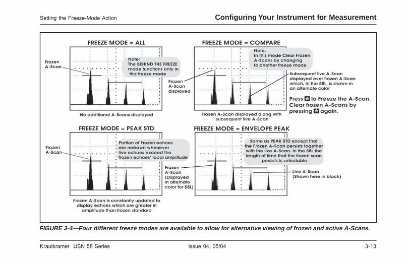
Krautkramer USN 58 Series Issue 04, 05/04 3-13
Krautkramer USN 58 Series Issue 04, 05/04 3-13
Setting the Freeze-Mode Action Configuring Your Instrument for Measurement
FIGURE 3-4—Four different freeze modes are available to allow for alternative viewing of frozen and active A-Scans.
FIGURE 3-4—Four different freeze modes are available to allow for alternative viewing of frozen and active A-Scans.
Setting the Freeze-Mode Action Configuring Your Instrument for Measurement
3-14 Issue 04, 05/04 Krautkramer USN 58 Series
3-14 Issue 04, 05/04 Krautkramer USN 58 Series
Configuring Your Instrument for Measurement Using Angle Beam Probes and the TRIG Menu
• COMPARE—Freezes the currently active A-Scan onthe display screen (which is displayed in analternate color in the 58L) then displays subsequentlive A-Scans. Frozen A-Scan is cleared by selectingan alternative FREEZE MODE
• PEAK STD—The frozen A-Scan is displayed andadjusted to match subsequent echoes wheneverhigher-amplitude echoes are measured. This has theeffect of “building” onto the frozen A-Scan whenevera higher-amplitude echo is encountered.
• 58R ENVELOPE PEAK—The frozen A-Scan isdisplayed and adjusted (just as in PEAK STDmode). Each displayed point remains until another ofgreater amplitude occurs. Simultaneously,subsequent live echoes are also displayed.
• 58L ENVELOPE (PEAK, .5S, 1S, 2S)—The frozenA-Scan is displayed and adjusted (just as in PEAKSTD) except that the frozen A-Scan persists for thespecified time. Depending on the ENVELOPE mode(.5S, 1S, 2S) selected, the points in the FrozenA-Scan are automatically replaced by live readingsat .5, 1, or 2 second intervals. When EnvelopePEAK is selected, each point remains until another
of greater amplitude occurs. (Simultaneously,subsequent live echoes are also displayed in theselected A-Scan color.)
H Note:
Behind the Freeze Mode is a special feature whichallows for limited dynamic time-base adjustment offrozen echoes. This mode is only available whenFREEZE MODE is set to ALL. In this mode (which isillustrated in section 4.9) the A-Scan display delay andrange, as well as the gate start, width, and thresholdcan all be adjusted after an A-Scan is frozen. Adjustingthese settings will cause the related measurements tochange.
3.4 Using Angle Beam Probesand the TRIG Menu
When connecting an angle beam probe to theinstrument, adjustments must be made for probecharacteristics as well as test-piece geometry. Thesefeatures are shown in Figure 3-5 and include
• Probe Angle
Configuring Your Instrument for Measurement Using Angle Beam Probes and the TRIG Menu
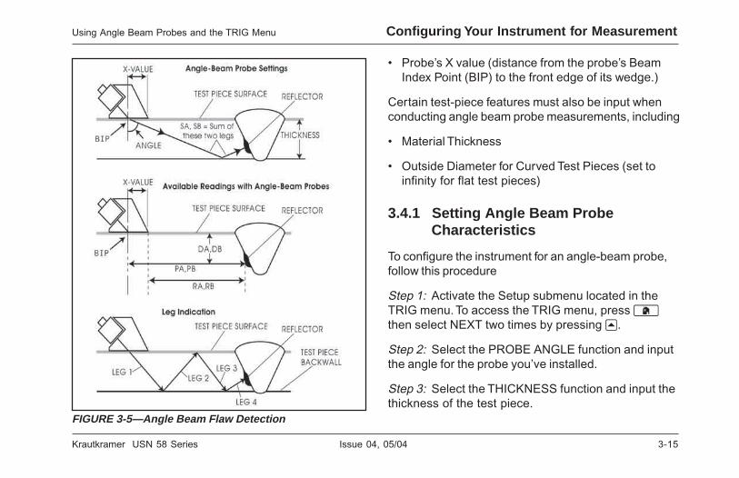
Krautkramer USN 58 Series Issue 04, 05/04 3-15
Krautkramer USN 58 Series Issue 04, 05/04 3-15
Using Angle Beam Probes and the TRIG Menu Configuring Your Instrument for Measurement
• Probe’s X value (distance from the probe’s BeamIndex Point (BIP) to the front edge of its wedge.)
Certain test-piece features must also be input whenconducting angle beam probe measurements, including
• Material Thickness
• Outside Diameter for Curved Test Pieces (set toinfinity for flat test pieces)
3.4.1 Setting Angle Beam ProbeCharacteristics
To configure the instrument for an angle-beam probe,follow this procedure
Step 1: Activate the Setup submenu located in theTRIG menu. To access the TRIG menu, press hthen select NEXT two times by pressing u.
Step 2: Select the PROBE ANGLE function and inputthe angle for the probe you’ve installed.
Step 3: Select the THICKNESS function and input thethickness of the test piece.
FIGURE 3-5—Angle Beam Flaw Detection
Using Angle Beam Probes and the TRIG Menu Configuring Your Instrument for Measurement

3-16 Issue 04, 05/04 Krautkramer USN 58 Series
3-16 Issue 04, 05/04 Krautkramer USN 58 Series
Configuring Your Instrument for Measurement Displaying Measured Readings
Step 4: Select the X VALUE function and input theuser-determined X value for the probe. When desired,this compensates for the distance from the BIP to thefront of the probe’s wedge.
Step 5: Select the O-DIAMETER function and inputthe outside diameter of a curved test piece (whenusing angle beam probes only). Note that this valueshould be set to FLAT when evaluating flat(non-curved) test pieces. Also, note that whenO-DIAMETER is set to any value other then FLAT, thed will appear in the icon bar near the top right-handcorner of the instrument display. If the definedgeometry is outside of the instrument’s curved test-piece capability, the d will be displayed.
3.4.2 Indicating Leg with Color (58L)
The leg in which a reflector is encountered, asidentified in Figure 3-5, can be visually indicated on theinstrument display using color. Setting the COLORLEG function (located in the COLORING submenu ofthe TRIG menu) to either ASCAN or GRID will causeeach ultrasonic leg to be displayed in a unique color.
When set to A-SCAN (meaning the leg-indicating coloris applied to the A-Scan itself, and not the background)the following requirements must be met before theCOLOR LEG function will operate:
• Start mode of Gates A and B must be set to IP
• Display Start mode must be set to IP
• Freeze mode must be set to ALL or PEAK
• A-Scan Enhance must be set to NONE orBASELINE BREAK
3.5 Displaying MeasuredReadings
The USN 58 is capable of displaying up to fourmeasured readings at one time. Parameters availablefor display include the following (availability dependson instrument configuration and operating mode):
• A%A—Amplitude (as a % of full-screen height) ofthe highest echo to cross A-Gate
• A%B—Amplitude (as a % of full-screen height) ofthe highest echo to cross B-Gate
Configuring Your Instrument for Measurement Displaying Measured Readings

Krautkramer USN 58 Series Issue 04, 05/04 3-17
Krautkramer USN 58 Series Issue 04, 05/04 3-17
Displaying Measured Readings Configuring Your Instrument for Measurement
• dBtA—dB difference between the height of A-Gateand the height of the highest echo in A-Gate.(available when AMPLITUDE is set to dBTHRESHOLD)
• dBtB—dB difference between the height of B-Gateand the height of the highest echo in B-Gate.(available when AMPLITUDE is set to dB THRES-HOLD)
• dBrA—dB difference between the reference echo theheight of the highest echo in A-Gate. (available whenAMPLITUDE is set to dB THRESHOLD and dB REFis ON)
• dBrB—dB difference between the reference echoand the height of the highest echo in B-Gate.(available when AMPLITUDE is set to dB THRES-HOLD and dB REF is ON)
Note that when S, D, P, or R readings are displayed,the Gate-Detection Mode (3.1.2) setting for thereferenced gate (A or B) is indicated by a (PeakMode) or a / (Flank Mode).
• SA—Sound-Path distance or duration representedby the highest echo to cross A-Gate
• SB—Sound-Path distance or duration representedby the highest echo to cross B-Gate
• SBA—Sound-Path distance or duration from thehighest echo in A-Gate to the echo in B-Gate.Reading is only available if B-Gate and A-Gate areon.
• DA—Material-thickness depth from the test-piecesurface (the probe-contacted side) to the reflectorrepresented by the echo in A-Gate. (see Figure 3-5)
• DB—Material-thickness depth from the test-piecesurface (the probe-contacted side) to the reflectorrepresented by the echo in B-Gate. (see Figure 3-5)
• DBA—Material-thickness depth from the reflectorrepresented by the echo in A-Gate to the onerepresented by the echo in B-Gate.
• PA—Projection distance from the probe’s BIP to thereflector represented by the echo in A-Gate. (seeFigure 3-5)
Displaying Measured Readings Configuring Your Instrument for Measurement

3-18 Issue 04, 05/04 Krautkramer USN 58 Series
3-18 Issue 04, 05/04 Krautkramer USN 58 Series
Configuring Your Instrument for Measurement Displaying Measured Readings
• PB—Projection distance from the probe’s BIP to thereflector represented by the echo in B-Gate. (seeFigure 3-5)
• PBA—Projection distance from the reflectorrepresented by the echo in A-Gate to the onerepresented by the echo in B-Gate.
• RA—Projection distance from the probe’s BIP to thereflector represented by the echo in A-Gate, minusthe inputted X-VALUE. (see Figure 3-5)
• RB—Projection distance from the probe’s BIP to thereflector represented by the echo in B-Gate, minusthe inputted X-VALUE. (see Figure 3-5)
• RBA—Projection distance from the reflectorrepresented by the echo in A-Gate to the onerepresented by the echo in B-Gate, minus theinputted X-VALUE.
• LA—Leg Indicator identifies on which leg thereflector represented by the echo in A-Gate wasdetected (Legs 1 through 5). (see Figure 3-5)
• LB—Leg Indicator identifies on which leg thereflector represented by the echo in B-Gate wasdetected (Legs 1 through 5). (see Figure 3-5)
• LBA—Indicates the number of legs between thereflector represented by the echo in A-Gate and theone represented by the echo in B-Gate.
• OFF—No reading will be displayed in the readingbox.
The four measured readings can be displayed in any ofthe four small reading boxes at the top of the displayscreen. In addition, the result displayed in one of thefour small boxes can be shown in the large reading box(see Figure 3-6). Also note that when time or thicknessreadings are displayed, the detection method selectedfor that gate is indicated with a ^ (representing PEAK)or / (representing FLANK). See 3.1.2 to selectdetection methods.
Assigning Measured Readings to theDisplayed Reading Boxes(BASIC-RESULTS-READING #)
The display includes a total of five boxes wheremeasured values can be displayed. Four “small”reading boxes can each contain one of four measured
Configuring Your Instrument for Measurement Displaying Measured Readings

Krautkramer USN 58 Series Issue 04, 05/04 3-19
Krautkramer USN 58 Series Issue 04, 05/04 3-19
Displaying Measured Readings Configuring Your Instrument for Measurement
Displaying Measured Readings Configuring Your Instrument for Measurement
FIGURE 3-6—The RESULTS submenu is used to specify which measured values to display.
FIGURE 3-6—The RESULTS submenu is used to specify which measured values to display.

3-20 Issue 04, 05/04 Krautkramer USN 58 Series
3-20 Issue 04, 05/04 Krautkramer USN 58 Series
Configuring Your Instrument for Measurement Saving the Instrument Configuration in a Data Set
values. A “large” reading box can display, in a largerformat, any one of the values shown in the smallboxes. To define the reading-box contents:
Step 1: Activate the BASIC menu.
Step 2: Select the RESULTS submenu.
Step 3: Select the READING box location you wish tospecify and choose from several of the selectionslisted above (available readings depend on designatedoperating mode):
H Note:
Under certain conditions (when a DGS reference echois stored, while TCG reference points are beingrecorded, or when AWS MODE is ON) twomeasurement result boxes will be automatically set (ifnot already configured) to display SA and A%A values.These result selections will remain locked until theDGS reference is deleted, the TCG recording processis finished, or AWS MODE is turned OFF.
Step 4: The large display box is modified from theTEST menu. Access the Test menu by pressing X,then press u below the LRG DISP selection until thelarge reading box contains the desired value.
H Note:
Only thickness measurements contained in the largedisplay box can be stored in data logger files.
3.6 Saving the InstrumentConfiguration in a Data Set
Instrument settings can be stored as Data Sets. Thosefunctional settings that are saved within a data set areshown in Table 5.1. When a stored data set is laterrecalled, all active functional settings are replaced withthose settings contained in the data set, and thestored A-Scan is displayed and frozen on the displayscreen (if stored with data set). Once a data set isrecalled, the newly active functional settings may bemodified. Anytime that data set is recalled, thefunctional settings will be returned to their initiallystored values. The operating parameters of a storeddata set can be modified after recalling the data set byselecting SAVE EDITS in the ACTION function, thenfollowing the on-screen instructions.
See section 5.1.2 to create a data set file.
Configuring Your Instrument for Measurement Saving the Instrument Configuration in a Data Set

Krautkramer USN 58 Series Issue 04, 05/04 3-21
Krautkramer USN 58 Series Issue 04, 05/04 3-21
3.7 Using the Master Lock (allmodels) Function or the LockKey (58L) to PreventAdjustment
To prevent modification of settings (except for the GainKnob), the instrument may be locked using theMASTER LOCK function. Alternatively, pressing (58L only) prevents modifications of settings anddisables the gain knob. When the instrument is locked,the x will appear in the upper left corner of the displayscreen. To lock the instrument (except for the GainKnob):
Step 1: Activate the Options submenu (located in theBASIC Menu).
Step 2: Select the MASTER LOCK function bypressing v.
Step 3: Turning the MASTER LOCK ON will cause thex to appear in the upper right corner of the displayscreen and will prevent further adjustment of mostinstrument settings. Setting this function to OFF willunlock the instrument.
Using the Master Lock Function to Prevent Setting Adjustment Configuring Your Instrument for Measurement
Using the Master Lock Function to Prevent Setting Adjustment Configuring Your Instrument for Measurement
Locking the Gain and Function RotaryKnobs
The gain and function knobs can be locked so thatturning either knob has no effect on the instrument.This feature operates independently of the instrument’sMaster Lock and x (on the 58L) and does not preventadjustment of function values as long as thosechanges are made by pressing a function key (v). Tolock the gain and function knobs:
Step 1: Activate the TEST MENU by pressing X.
Step 2: Press u below the selection titled dB STEP.
Step 3: Continue pressing u while observing that thevalue of dB STEP (in the upper left-hand corner of thedisplay) changes to various step values. When theword LOCK appears as the dB STEP value, the gainand function knobs are locked.
Step 4: To unlock the knobs, change the setting of dBSTEP to some value other than LOCK.

3-22 Issue 04, 05/04 Krautkramer USN 58 Series
3-22 Issue 04, 05/04 Krautkramer USN 58 Series
THIS PAGE WAS INTENTIONALLY LEFT BLANK.
THIS PAGE WAS INTENTIONALLY LEFT BLANK.

Krautkramer USN 58 Series Issue 04, 05/04 4-1
Krautkramer USN 58 Series Issue 04, 05/04 4-1
Using the Test Menu 4
Using the Test Menu 4

4-2 Issue 04, 05/04 Krautkramer USN 58 Series
4-2 Issue 04, 05/04 Krautkramer USN 58 Series
Using the Test Menu Accessing the TEST Menu
This chapter explains how to use the features found inyour instrument’s Test Menu, how to freeze a displayedA-Scan, and how to access the Help Screens. You’llalso learn how to use the full range of gain-adjustments. In this chapter, you’ll learn how to
• Access the Test Menu (section 4.1)
• Adjust the A-Scan gain using the Gain Knob and thedB STEP feature (section 4.2)
• Use the dB REFERENCE feature (section 4.3)
• Change the displayed VIEW (section 4.4)
• Navigate through an active data logger file andattach NOTES to thickness measurements (section4.5)
• MAGNIFY the contents of a selected gate (section4.6)
• Reset latched alarms (section 4.7)
• Select the value to view in the LARGE DISPLAYbox (section 4.8)
• FREEZE and unfreeze the A-Scan and work in theBehind the Freeze Mode (section 4.9)
• Access the instrument‘s HELP SCREENS (section4.10)
4.1 Accessing the TEST Menu
The Test Menu contains six features which are directlycontrolled with the six Menu Keys arranged under thedisplay screen. To access the Test Menu fromanywhere else in the menu system, press X. Thedisplay will appear as shown in Figure 4-1 (if the probeis coupled to a test piece) with one possible exception.The function bar displayed when X is pressed willcontinue to be displayed together with the Test Menu.Pressing X when the Test Menu is displayed willchange the menu bar to the grid markers. Anotherpress will place display delay and range values underthe A-Scan while a fourth press returns the display tothe menu location from which it originated.
Using the Test Menu Accessing the TEST Menu

Krautkramer USN 58 Series Issue 04, 05/04 4-3
Krautkramer USN 58 Series Issue 04, 05/04 4-3
Accessing the TEST Menu Using the Test Menu
FIGURE 4-1—The Test Menu includes these menu-key controlled features as well as whichever four functions wereactive when XXXXX was pressed. While the placement of some keys vary, all USN 58 series instruments display the sametest menu.
FIGURE 4-1—The Test Menu includes these menu-key controlled features as well as whichever four functions wereactive when XXXXX was pressed. While the placement of some keys vary, all USN 58 series instruments display the sametest menu.
Accessing the TEST Menu Using the Test Menu

4-4 Issue 04, 05/04 Krautkramer USN 58 Series
4-4 Issue 04, 05/04 Krautkramer USN 58 Series
Using the Test Menu Setting the Gain
4.2 Setting the Gain
Instrument gain, which increases and decreases theheight of a displayed A-Scan, is adjusted with the GainKnob as shown in Figure 4-2. The instrument’s gain canbe adjusted while in any menu location except whenthe dB STEP feature is set to LOCK. Note that theMASTER LOCK function, which causesx to appear inthe icon bar, does not prevent gain adjustment.
4.2.1 Changing the Gain-AdjustmentIncrement (dB STEP)
When adjusting the A-Scan gain, each click of thegain-adjustment knob increases or decreases the gainlevel by a dB increment equal to the dB STEP. Severalvalues can be specified for dB STEP, including a user-specified gain step, known as the USER GAIN STEP,and a gain Function knob adjustment LOCK, whichprevents any gain adjustment and any changes usingthe Function knob. To select one of the existing dBSTEP values:
Step 1: Activate the TEST MENU by pressing X andproceed to Step 2 or press V and immediatelyproceed to Step 3.
Step 2: Press u below the feature titled dB STEP.
Step 3: Note that the dB STEP (gain-adjustmentincrement) value, as labeled in Figure 4-2, changes asyou continue to push u. Available increments include:0.1 dB, 0.5 dB, 1.0 dB, 2.0 dB, 6 dB, a user-definedGain Step (if one has been defined), and LOCK. Tospecify a user-defined dB STEP value, see the nextmanual procedure. Note that setting the dB STEP toLOCK prevents adjustment of the instrument gain andprevents any changes using the Function knob. Alsonote that the dB STEP setting can be changed fromthe GAIN submenu found in the PLSRCVR menu.
Step 4: Once a dB STEP value has been selected,each click of the Gain Knob will increase or decreasethe instrument’s gain by the dB STEP increment.
Using the Test Menu Setting the Gain

Krautkramer USN 58 Series Issue 04, 05/04 4-5
Krautkramer USN 58 Series Issue 04, 05/04 4-5
Setting the Gain Using the Test Menu
FIGURE 4-2—Setting instrument gain and the gain adjustment capability
FIGURE 4-2—Setting instrument gain and the gain adjustment capability
Setting the Gain Using the Test Menu

4-6 Issue 04, 05/04 Krautkramer USN 58 Series
4-6 Issue 04, 05/04 Krautkramer USN 58 Series
Using the Test Menu Using the dB Reference Feature
H Note:
Setting dB STEP to LOCK prevents any adjustmentusing either the Gain or Function Knob.
4.2.2 Setting the User-Defined Gain Step(PLSRCVR-GAIN-USER GAIN)
When adjusting the A-Scan gain, each click of thegain-adjustment knob increases or decreases the gainlevel by the amount of the dB STEP (see above foradjusting the dB STEP). Several values can bespecified for dB STEP, including a user-specified gainstep, known as USER GAIN STEP. To input a user-specified gain step:
Step 1: Activate the GAIN submenu (located in thePlsrcvr Menu) by pressing u below it. Four functionswill appear down the right side of the display screen.
Step 2: Press v next to the selection titled USERGAIN STEP.
Step 3: To set the USER GAIN STEP size, continuepressing v or turn the function knob.
4.3 Using the dB ReferenceFeature
When dB REF is activated, the amplitude of thehighest echo in A-Gate becomes the reference echoagainst which subsequent echo amplitudes areevaluated. At the time of dB REF activation, the gainsetting also becomes a reference against whichsubsequent gain values are compared.
dB REF is activated from the Test Menu by pressing ubelow the dBREF selection. It’s important to rememberthat the highest echo in A-Gate and GAIN setting,when dB REF is selected, will become the referenceamplitude and gain value for as long as dB REF isactivated. Note that dB REF can also be turned on fromthe GAIN Submenu found in the PLSRCVR Menu.
H Note:
The reference echo amplitude must not exceed 100%of full-screen height.
H Note:
Setting dB STEP to LOCK prevents any adjustmentusing either the Gain or Function Knob.
4.2.2 Setting the User-Defined Gain Step(PLSRCVR-GAIN-USER GAIN)
When adjusting the A-Scan gain, each click of thegain-adjustment knob increases or decreases the gainlevel by the amount of the dB STEP (see above foradjusting the dB STEP). Several values can bespecified for dB STEP, including a user-specified gainstep, known as USER GAIN STEP. To input a user-specified gain step:
Step 1: Activate the GAIN submenu (located in thePlsrcvr Menu) by pressing u below it. Four functionswill appear down the right side of the display screen.
Step 2: Press v next to the selection titled USERGAIN STEP.
Step 3: To set the USER GAIN STEP size, continuepressing v or turn the function knob.
4.3 Using the dB ReferenceFeature
When dB REF is activated, the amplitude of thehighest echo in A-Gate becomes the reference echoagainst which subsequent echo amplitudes areevaluated. At the time of dB REF activation, the gainsetting also becomes a reference against whichsubsequent gain values are compared.
dB REF is activated from the Test Menu by pressing ubelow the dBREF selection. It’s important to rememberthat the highest echo in A-Gate and GAIN setting,when dB REF is selected, will become the referenceamplitude and gain value for as long as dB REF isactivated. Note that dB REF can also be turned on fromthe GAIN Submenu found in the PLSRCVR Menu.
H Note:
The reference echo amplitude must not exceed 100%of full-screen height.
Using the Test Menu Using the dB Reference Feature

Krautkramer USN 58 Series Issue 04, 05/04 4-7
Krautkramer USN 58 Series Issue 04, 05/04 4-7
Using the dB Reference Feature Using the Test Menu
FIGURE 4-3—dB Ref capabilities
FIGURE 4-3—dB Ref capabilities
Using the dB Reference Feature Using the Test Menu

4-8 Issue 04, 05/04 Krautkramer USN 58 Series
4-8 Issue 04, 05/04 Krautkramer USN 58 Series
Using the Test Menu Changing the Displayed VIEW
Once dB REF is activated, the Gain-Display Blocklists both the Reference Gain and Incremental Gain
levels. Also, the icon will appear. The Reference
Gain remains constant throughout the dB REF sessionwhile the Incremental Gain value changes as the GainKnob is rotated (Figure 4-3).
After dB REF is activated, any amplitudemeasurements are stated in relation to the referenceecho amplitude. Available amplitude readings (seesection 3.5 to change display-box reading values)when operating in dB REF mode are
• dBrA—dB difference between the reference echoand the highest echo to cross A-Gate (availablewhen AMPLITUDE is set to dB THRESHOLD).
• dBrB—dB difference between the reference echoand the highest echo to cross B-Gate (availablewhen AMPLITUDE is set to dB THRESHOLD).
4.4 Changing the Displayed VIEW
The instrument is capable of displaying an activeA-Scan in three different VIEW modes (Figures 4-4 and4-5) including:
• Full-screen A-Scan
• Half-screen A-Scan with memory and file status inthe lower portion of the display
• Half-screen A-Scan with File Navigation Window inthe lower portion of the display (only when a datalogger file is active)
To change the displayed VIEW, activate the Test Menuand press below the VIEW feature.
Using the Test Menu Changing the Displayed VIEW

Krautkramer USN 58 Series Issue 04, 05/04 4-9
Krautkramer USN 58 Series Issue 04, 05/04 4-9
Changing the Displayed VIEW Using the Test Menu
FIGURE 4-4—Three display options are available to allow the user to view an A-Scan while navigating through a datalogger file or examining existing file count and available memory.
FIGURE 4-4—Three display options are available to allow the user to view an A-Scan while navigating through a datalogger file or examining existing file count and available memory.
Using the Test MenuChanging the Displayed VIEW

4-10 Issue 04, 05/04 Krautkramer USN 58 Series
4-10 Issue 04, 05/04 Krautkramer USN 58 Series
Using the Test Menu Navigating Through a Data Logger File and Attaching Notes
4.5 Navigating Through a DataLogger File and AttachingNotes
Thickness measurements may be stored in data loggerfiles (see section 5.1 to create a data logger file). Aftera data logger file is created, the user may selectspecific file locations, make them active, and storethickness readings in those locations by pressing C(see 5.2 to store thickness measurements). The usermay also attach one or more notes to each data loggerfile location. To navigate through the file contents of adata logger file
Step 1: Ensure that a data logger file is open byselecting it with the FILENAME function (in the Filessubmenu). (VIEW is not applicable to data set files asthey do not contain thickness measurements.)
Step 2: Activate the Test Menu (or access the DLDATA Function from the FILES menu).
Step 3: Press u below the VIEW selection.
Step 4: Follow the navigation instructions and attachnotes as shown in Figure 4-5. Note that all availablenotes can be displayed by setting the NOTE ACTIONfunction to DISPLAY NOTES.
4.6 Magnifying the Contents of aGate
Whenever an A-Scan is active, presssing H enlargesthe displayed portion of the A-Scan contained in aspecified gate. This can also be accomplished whenthe Test Menu (X) is activated, by pressing u belowthe MAGNIFY feature. Any available gate may bespecified. The width of the magnified gate determinesthe level of magnification. This is because the displayis magnified until the gate width equals 100% full-screen width. (Figure 4-6) The display will contain themagnified view until H is pressed a second time orMAGNIFY is again selected with u.
Using the Test Menu Navigating Through a Data Logger File and Attaching Notes

Krautkramer USN 58 Series Issue 04, 05/04 4-11
Krautkramer USN 58 Series Issue 04, 05/04 4-11
Magnifying the Contents of a Gate Using the Test Menu
FIGURE 4-5—This display option allows the user to view an A-Scan while navigating through a data logger file. In thisview the contents and attached notes of an active data logger file are visible.
FIGURE 4-5—This display option allows the user to view an A-Scan while navigating through a data logger file. In thisview the contents and attached notes of an active data logger file are visible.
Magnifying the Contents of a Gate Using the Test Menu

4-12 Issue 04, 05/04 Krautkramer USN 58 Series
4-12 Issue 04, 05/04 Krautkramer USN 58 Series
Using the Test Menu Magnifying the Contents of a Gate
FIGURE 4-6—The Magnify feature magnifies the A-Scan contents of a gate. The gate to be magnified is selected bythe user.
FIGURE 4-6—The Magnify feature magnifies the A-Scan contents of a gate. The gate to be magnified is selected bythe user.
Using the Test Menu Magnifying the Contents of a Gate

Krautkramer USN 58 Series Issue 04, 05/04 4-13
Krautkramer USN 58 Series Issue 04, 05/04 4-13
Resetting Latched Alarms Using the Test Menu
Selecting the Gate to Be Magnified(GATES-GATEMODE-MAGNIFY GATE)
Pressing u below the MAGNIFY selection (wheneverthe Test Menu is active) magnifies the portion of theA-Scan that’s displayed in the specified gate. Tospecify the magnified gate:
Step 1: Activate the GATEMODE submenu.
Step 2: Select the MAGNIFY GATE function andspecify the desired gate.
4.7 Resetting Latched Alarms
When a TTL output and the corresponding alarmindication light are activated, and TTL output mode isset to LATCHED (section 3.1.5) the warning will remainset until cleared. To clear a latched alarm:
Step 1: Activate the Test Menu.
Step 2: Press u below the ALRM RST selection orreset the alarm using an external signal via the RealTime I/O port.
4.8 Large Display Box-Specifyingthe Contents (LRG DISP)
The USN 58 is capable of displaying up to fourmeasured readings in the four small reading boxes atthe top of the display screen (see 3.4 to set the smallreading box values). In addition, the result displayed inone of the four small boxes can be shown in the largereading box in the top right-hand corner of the display(see Figure 4-7).
The large display box’s contents are modified from theTEST menu by pressing u below the LRG DISPselection until the large reading box contains thedesired value.
H Note:
When so configured, pressing C stores the value inthe Large Display Box in an active data logger file, oroutputs this value via the RS 232 Port. Only thicknessreadings (and not amplitude readings) may be stored indata logger files. Section 5.2 explains how to configurethe C function. The value displayed in the Large
Resetting Latched Alarms Using the Test Menu

4-14 Issue 04, 05/04 Krautkramer USN 58 Series
4-14 Issue 04, 05/04 Krautkramer USN 58 Series
Using the Test Menu Large Display Box Specifying the Contents (LRG DISP)
FIGURE 4-7—Notice that when time or thickness readings (SA, SB, etc.) are displayed, in the small or large displayboxes, the detection method selected for that gate is indicated with a ^ (representing PEAK) or / (representingFLANK). Available readings are the same for all USN 58 series instruments.
FIGURE 4-7—Notice that when time or thickness readings (SA, SB, etc.) are displayed, in the small or large displayboxes, the detection method selected for that gate is indicated with a ^ (representing PEAK) or / (representingFLANK). Available readings are the same for all USN 58 series instruments.
Using the Test Menu Large Display Box Specifying the Contents (LRG DISP)

Krautkramer USN 58 Series Issue 04, 05/04 4-15
Krautkramer USN 58 Series Issue 04, 05/04 4-15
Freezing the A-Scan Display Using the Test Menu
Display Box is also used for the Smart View A-ScanMode selection. (Refer to section 6.3)
4.9 Freezing the A-Scan Display
Whenever an A-Scan is active, pressing the freeze key(W) freezes the A-Scan display. The active A-Scan willremain as it appeared when W was pressed and thedisplay will remain frozen until W is pressed again.There are several frozen-display configurations,however, that allow subsequent A-Scans to bedisplayed and evaluated against the frozen A-Scan(compare) or that adjust the frozen A-Scan wheneveran active echo is higher in amplitude (PEAK STD). Theconfiguration of the frozen display is determined by theFREEZE MODE setting (see section 3.3 to adjust thissetting). There are four freeze configurations, as shownin Figure 4-8.
While the display is frozen, the displayed readings arebased on the frozen echoes.
4.9.1 Working in the Behind the FreezeMode
Behind the Freeze Mode is a special feature, whichallows for limited dynamic time-base adjustment offrozen echoes. This mode is only available whenFREEZE MODE is set to ALL. In this mode the A-Scan display delay and range, as well as the gatestart, width, and threshold can all be adjusted (by alimited amount) after an A-Scan is frozen. Adjustingthese settings will cause the related measurements tochange.
Freezing the A-Scan Display Using the Test Menu

4-16 Issue 04, 05/04 Krautkramer USN 58 Series
4-16 Issue 04, 05/04 Krautkramer USN 58 Series
Using the Test Menu Freezing the A-Scan Display
FIGURE 4-8—There are four different freeze modes available.
FIGURE 4-8—There are four different freeze modes available.
Using the Test Menu Freezing the A-Scan Display

Krautkramer USN 58 Series Issue 04, 05/04 4-17
Krautkramer USN 58 Series Issue 04, 05/04 4-17
Accessing the HELP SCREENS Using the Test Menu
4.10 Accessing the HELPSCREENS
Based on the submenu selected, one or morefunctions appear in the function bar. These fourfunction positions and the function bar are identified inFigure 4-9. The HELP SCREEN contains a brief
FIGURE 4-9 —The Help Screen contains a description for each displayed function. The USN 58L Help Screen displayincludes the active function bar.
explanation for each displayed function. Press ? toaccess the HELP SCREENS for the displayedfunctions. The help screen will remain active until ? ispressed again. Note that selecting another submenuand changing the displayed functions causes thehelp-screen information for the new functions to bedisplayed.
4.10 Accessing the HELPSCREENS
Based on the submenu selected, one or morefunctions appear in the function bar. These fourfunction positions and the function bar are identified inFigure 4-9. The HELP SCREEN contains a brief
explanation for each displayed function. Press ? toaccess the HELP SCREENS for the displayedfunctions. The help screen will remain active until ? ispressed again. Note that selecting another submenuand changing the displayed functions causes thehelp-screen information for the new functions to bedisplayed.
FIGURE 4-9 —The Help Screen contains a description for each displayed function. The USN 58L Help Screen displayincludes the active function bar.
Accessing the HELP SCREENS Using the Test Menu

4-18 Issue 04, 05/04 Krautkramer USN 58 Series
4-18 Issue 04, 05/04 Krautkramer USN 58 Series
THIS PAGE WAS INTENTIONALLY LEFT BLANK.
THIS PAGE WAS INTENTIONALLY LEFT BLANK.

Krautkramer USN 58 Series Issue 04, 05/04 5-1
Krautkramer USN 58 Series Issue 04, 05/04 5-1
Storing and Outputting Data 5
Storing and Outputting Data 5

5-2 Issue 04, 05/04 Krautkramer USN 58 Series
5-2 Issue 04, 05/04 Krautkramer USN 58 Series
Storing and Outputting Data
Your instrument is equipped with a data-storagesystem. A-Scans instrument settings, thicknessreadings, and notes can be stored in data files for laterretrieval. Information to be contained in report headers,as well as short memos may also be included in files.Files are created, modified, recalled, and deleted byusing the FILES MENU (Figure 5-1).
Data logger file contents, along with specifiedattachments can be output to a personal computer orprinter. The outputting functions are accessed throughthe FILES MENU.
Finally, instrument settings can be stored as data sets.Most functional settings are saved within a data set.When a stored data set is later recalled, all activefunction settings will be modified to match thosecontained in the data set. The FILES MENU is used tocreate, recall, and delete data sets. (See section 3.5 towork with data sets).
In this chapter, you’ll learn how to work with all FILESMENU functions including:
• CREATE and name new (data logger or data set)files (section 5.1)
• SAVE EDITS to existing files (section 5.1.3)
• Store thickness measurements in a data logger file(section 5.2)
• RECALL and PREVIEW existing files (section 5.3)
• Delete (CLEAR) existing files (section 5.4)
• Create and attach a MEMO to a Data file (5.5)
• Input REPORT-HEADER information (section 5.6)
• Edit NOTES to be attached to stored readings(section 5.7)
• Specify REPORT Content and print reports (section5.8)
• Configure the instrument to output data to a printervia the RS-232 serial port (section 5.9)
• Configure the instrument to output data to a personalcomputer via the RS-232 serial port. (section 5.10)
• Set the action taken when C is pressed(section 5.9.1)
Storing and Outputting Data
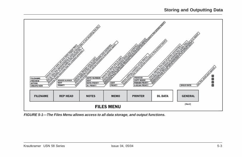
Krautkramer USN 58 Series Issue 04, 05/04 5-3
Krautkramer USN 58 Series Issue 04, 05/04 5-3
Storing and Outputting Data
FIGURE 5-1—The Files Menu allows access to all data storage, and output functions.
FIGURE 5-1—The Files Menu allows access to all data storage, and output functions.
Storing and Outputting Data

5-4 Issue 04, 05/04 Krautkramer USN 58 Series
5-4 Issue 04, 05/04 Krautkramer USN 58 Series
Storing and Outputting Data Data Set and Data Logger Files
5.1 Data Set and Data Logger Files
Data set files are used to store a specific instrument-setup configuration. Instrument settings, and the activeA-Scan, present when the data set file is created arestored in the file. Table 5-1 lists all settings saved in adata set file. When the data set file is recalled, allinstrument settings are modified to match the settingsstored in the data set file. However, once a data set fileis opened, instrument settings may be modified fromtheir data-set-file configurations. However, thesechanges will only affect the data set file ifadditional actions are taken to do so as described
in section 5.1.3. Otherwise, the original filestructure will remain as-saved.
Data logger files are used to store thicknessmeasurements, along with the same instrumentsettings stored in data set files (Table 5-2). Data loggerfiles can be arranged into one of three file types:LINEAR (a series of 1 to 99,999 consecutive datapoints), GRID (a matrix of data points up to 701 x 701),or CUSTOM LINEAR (up to 999 data points stored inup to 9,999 locations). After a data logger file iscreated, thickness data can be stored, erased, andmodified in that file.
Storing and Outputting Data Data Set and Data Logger Files

Krautkramer USN 58 Series Issue 04, 05/04 5-5
Krautkramer USN 58 Series Issue 04, 05/04 5-5
Data Set and Data Logger Files Storing and Outputting Data
Data Set and Data Logger Files Storing and Outputting Data
elbaT 5 1-
gnitteSeliFteSataD s
edoMnoitceteDA tratSB pmAecnerefeRSGD tesffOFI 1#wodniWesioN redaeHtropeR
cigoLA edoMtratSB niaGecnerefeRSGD tratSFI 2#wodniWesioN etaGdetceleS
tratSA dlohserhTB epyTecnerefeRSGD edoMtratSFI 3#wodniWesioN yalpsiDevruCGCT
edoMtratSA htdiWB noitaunettAtseTSGD dlohserhTFI noitcAetoN stnioPniaGGCT
dlohserhTA niaGrotaunettAWB ssoLrefsnarTSGD htdiWFI setoN stnioPemiTGCT
htdiWA edoMrotaunettAWB maiDlatXSGD xednIyalpsiDegraL stnioPGCTfo# edoMGCT
edoMmralA )L85(geLroloC ycneuqerFlatXSGD SOL retemaiDretuO edoMdroceRGCT
detceleSmralA gnipmaD yaleDyalpsiD etatSnoitacifingaM yaleDtuptuO pmAfeRGCT
edoMedutilpmA niaGfeRBD tratSyalpsiD etaGyfingaM edoMFRP edoMtratSGCT
ecnahnEnacsA edoMfeRBD edoMlauD eulaVFRPlaunaM elgnAeborP ssenkcihTgirT
edoMnacsA edoMyaleD ygrenE kcoLretsaM yaleDeborP eulaVXgirT
feRkcihTlaCotuA noitcerroCpmASGD erotSitluMeliF lairetaM egnaR tnemngissA1#LTT
feRnihTlaCotuA evruCSGD ycneuqerF mralAmumixaM 1#xednIgnidaeR tnemngissA2#LTT
noitaunettASWA yticoleVyaleDSGD petSniaG omeM 2#xednIgnidaeR tnemngissA3#LTT
noitacidnISWA tluseRlavESGD epyTdirG niaGuneM 3#xednIgnidaeR stinU
edoMSWA edoMSGD tuOdeepShgiH mralAmuminiM 4#xednIgnidaeR petSniaGresU
gnitaRSWA eborPSGD nroH 1#tnuoCesioN edoMnoitacifitceR yticoleV
ecnerefeRSWA noitaunettAfeRSGD edoMyaleDFI 2#tnuoCesioN tcejeR yticoleVhtaPretaW
edoMnoitceteDB dedroceRfeRSGD edoMnoitceteDFI 3#tnuoCesioN etaRpeR
cigoLB eziSfeRSGD cigoLFI

5-6 Issue 04, 05/04 Krautkramer USN 58 Series
5-6 Issue 04, 05/04 Krautkramer USN 58 Series
Storing and Outputting Data Data Set and Data Logger Files
5.1.1 Creating Data Set Files
To store instrument settings in a new data-set filefollow this procedure
Step 1: Activate the FILES MENU.
Step 2: With the FILENAME submenu selected, press(two times) v next to the CREATE NEW function.
Step 3: Note that the bottom of the display screencontains a default file name (the word “FILE” followedby a numeral). This name can be adjusted using the
USN 58’s Text-Entry feature (see description inFigure 5-2).
Step 4: Do not select a file type (LINEAR, GRID,CUSTOM LINEAR) as these only apply to data loggerfiles which contain stored thickness measurements(see section 5.1.2 to create data logger files).
Step 5: Once the desired file name is entered on thescreen, press v next to STORE. The instrument’ssettings have been saved in the data set file.
H Note:
The newly created file name automatically becomesthe default file name. This default name with incrementby 1 the next time a new file is created (i.e. after thefile name “GRIDz” is entered, the next default file namewill be “GRIDz1.”)
5.1.2 Creating Data Logger Files
To store thickness readings and instrument settings in anew data logger file follow this procedure (Figure 5-3).
Step 1: Activate the FILES MENU (located in theHOME MENU).
elbaT 5-2
ataD stnetnoCeliFreggoL
• seliftesatadnidevassgnittesretemarapllA)1-5elbaTotrefeR(
• stnemerusaeMssenkcihTderotS
• tnemerusaemssenkcihthcaerofsnoitacidnInoitacoL
• stnemerusaemssenkcihtotdehcattasgaTetoN
• elifehtotdehcattaomeM
• redaehtropers'eliF
Storing and Outputting Data Data Set and Data Logger Files

Krautkramer USN 58 Series Issue 04, 05/04 5-7
Krautkramer USN 58 Series Issue 04, 05/04 5-7
Data Set and Data Logger Files Storing and Outputting Data
FIGURE 5-2—The Text-Entry display allows you to quickly enter or edit file names, notes, report headers, memos, andother alphanumeric labels.
FIGURE 5-2—The Text-Entry display allows you to quickly enter or edit file names, notes, report headers, memos, andother alphanumeric labels.
Data Set and Data Logger Files Storing and Outputting Data

5-8 Issue 04, 05/04 Krautkramer USN 58 Series
5-8 Issue 04, 05/04 Krautkramer USN 58 Series
Storing and Outputting Data Data Set and Data Logger Files
Step 2: With the FILENAME submenu selected, press(two times) v next to the CREATE NEW function.
Step 3: Note that the bottom of the display screencontains a default file name (the word “FILE” followedby a numeral). This name can be adjusted using theUSN 58’s Text-Entry display (see description inFigure 5-2).
Step 4: Select a file type by pressing v next to thedesired type:
• LINEAR—contains up to 99,999 consecutivethickness measurements
• GRID—stores thickness measurements in a matrixformat (up to 701 rows and 701 columns) See notebelow related to the MULTISTORE feature.
• CUSTOM LINEAR—stores data in up to 9999locations, each containing from up to 999 points
Step 5: Set characteristics as shown in Figure 5-3.
H Note:
When a grid file is active, turning MULTISTORE ONallows 2, 3, or 4 thickness readings (from each of theRESULTS Boxes) to be simultaneously stored in an
equal number of grid positions by pressing C. Forthis feature to operate a grid file type must be active,the file must have MULTISTORE turned ON, andCOPY MODE must be set to LOG To FILE. Caution:the file will contain only a numerical thickness value,and will not identify the quantity (SA, A%A, etc.).
Step 6: Once the desired file name and characteristicsare entered, press v next to STORE. The data loggerfile has been created.
H Note:
The newly created file name automatically becomesthe default file name. This default name with incrementby 1 the next time a new file is created (i.e. after thefile name “GRIDz” is entered, the next default file namewill be “GRIDz1.”)
5.1.3 Editing Active Files
Parameters (other than recorded measurements) storedas part of an existing data set or data logger file canbe edited anytime the file is active. To save these editsto any active file do the following:
Step 1: Make all edits desired.
Step 2: With the FILENAME submenu selected, press(two times) v next to the CREATE NEW function.
Step 3: Note that the bottom of the display screencontains a default file name (the word “FILE” followedby a numeral). This name can be adjusted using theUSN 58’s Text-Entry display (see description inFigure 5-2).
Step 4: Select a file type by pressing v next to thedesired type:
• LINEAR—contains up to 99,999 consecutivethickness measurements
GRID—stores thickness measurements in a matrixformat (up to 701 rows and 701 columns) See notebelow related to the MULTISTORE feature.
• CUSTOM LINEAR—stores data in up to 9999locations, each containing from up to 999 points
Step 5: Set characteristics as shown in Figure 5-3.
H Note:
When a grid file is active, turning MULTISTORE ONallows 2, 3, or 4 thickness readings (from each of theRESULTS Boxes) to be simultaneously stored in an
equal number of grid positions by pressing C. Forthis feature to operate a grid file type must be active,the file must have MULTISTORE turned ON, andCOPY MODE must be set to LOG To FILE. Caution:the file will contain only a numerical thickness value,and will not identify the quantity (SA, A%A, etc.).
Step 6: Once the desired file name and characteristicsare entered, press v next to STORE. The data loggerfile has been created.
H Note:
The newly created file name automatically becomesthe default file name. This default name with incrementby 1 the next time a new file is created (i.e. after thefile name “GRIDz” is entered, the next default file namewill be “GRIDz1.”)
5.1.3 Editing Active Files
Parameters (other than recorded measurements) storedas part of an existing data set or data logger file canbe edited anytime the file is active. To save these editsto any active file do the following:
Step 1: Make all edits desired.
Storing and Outputting Data Data Set and Data Logger Files

Krautkramer USN 58 Series Issue 04, 05/04 5-9
Krautkramer USN 58 Series Issue 04, 05/04 5-9
Data Set and Data Logger Files Storing and Outputting Data
FIGURE 5-3—After selecting file type (LINEAR, GRID, or CUSTOM LINEAR) you must specify the applicable group offile characteristics.
FIGURE 5-3—After selecting file type (LINEAR, GRID, or CUSTOM LINEAR) you must specify the applicable group offile characteristics.
Data Set and Data Logger Files Storing and Outputting Data

5-10 Issue 04, 05/04 Krautkramer USN 58 Series
5-10 Issue 04, 05/04 Krautkramer USN 58 Series
Storing and Outputting Data Storing Thickness Measurements in Data Logger Files
Step 2: Set the ACTION function (in the FILENAMEsubmenu) to SAVE EDITS.
Step 3: Follow the on-screen instructions to make theedits to this file permanent.
5.2 Storing ThicknessMeasurements in DataLogger Files
Only data logger files can contain measurement data(data set files contain only instrument settings and anA-Scan) and only thickness measurements may bestored in data logger files. Thickness measurementscan be stored in active (newly created or recalled) datalogger files using as follows:
Step 1: Access the PRINTER Submenu (in the FILESMenu).
Step 2: Activate the COPY MODE function and selectLOG TO FILE. This sets the C action.
Step 3: Couple the probe to the test piece.
Step 4: With a thickness measurement in the LargeDisplay Window (see section 4.8 to change thecontents of the Large Display Box) press C.
Step 5: The thickness measurement will be stored inthe next available file location of the active data loggerfile. You can display the data logger file contents byfirst accessing the Test Menu (X), then the VIEWselection. (see sections 4.4 and 4.5 to change viewsand navigate through active data logger files).
5.3 Recalling Existing Data Files
Existing data files are typically accessed for thefollowing purposes:
• DATA SET FILES—accessing an existing file resetsthe current instrument setting to the stored data-set-file settings
• DATA LOGGER FILES—accessing an existing fileallows stored thickness measurements to bereplaced and/or new thickness values to be stored. Italso resets the current instrument setting to thestored data-logger-file settings and allows editing ofstored memos, report headers, and notes.
Storing and Outputting Data Storing Thickness Measurements in Data Logger Files

Krautkramer USN 58 Series Issue 04, 05/04 5-11
Krautkramer USN 58 Series Issue 04, 05/04 5-11
Deleting (CLEARING) Existing Data Files Storing and Outputting Data
To access an existing file:
Step 1: Activate the FILENAME submenu (in theFILES menu).
Step 2: Press v next to the FILENAME function.Press v or turn the Function Knob until the desired filename appears.
Step 3: Press v next to the ACTION function once,then turn the Function Knob until RECALL appears.Then press v again. (In this case, turning the knoband pressing the button perform different operations.)
Step 4: Press HOME to confirm
Step 5: If an A-scan is stored with the recalled dataset, press FREEZE to unfreeze the display andactivate the recalled data set.
Step 6: The selected file is now active. The instrumentsettings will be configured to those stored in the file.Thickness measurements may be stored in data loggerfiles as discussed in section 5.2.
5.3.1 Previewing Existing Data Files
Existing data files can be PREVIEWED rather thanRECALLED. Previewing only allows the user to viewthe report header and A-Scan stored with the filesettings. To preview an existing file:
Step 1: Activate the FILENAME submenu (in theFILES menu).
Step 2: Turn previewing ON by pressing v next to thePREVIEW function.
Step 3: Press v next to the FILENAME function.Press v or turn the Function Knob until the desired filename appears.
Step 4: The selected file can only be previewed. Onlythe file name, report header, and A-Scan stored withthe file will be displayed.
5.4 Deleting (CLEARING) ExistingData Files
Existing data files are deleted using this procedure:
Deleting (CLEARING) Existing Data Files Storing and Outputting Data
5-12 Issue 04, 05/04 Krautkramer USN 58 Series
5-12 Issue 04, 05/04 Krautkramer USN 58 Series
Storing and Outputting Data Creating a Memo
Step 1: Activate the FILENAME submenu (in theFILES menu).
Step 2: Press v next to the FILENAME function. Pressv or turn the Function Knob until the desired functionname appears.
Step 3: Press v next to the ACTION function once,then turn the Function Knob until CLEAR appears. Nowpress (two times) v next to the ACTION function.Follow the display-screen prompting and press h toconfirm the file-delete command.
Step 4: The deleted file may not be retrieved.
5.5 Creating a Memo
Memos are attached to data logger and data set filesat the time the files are stored. After a file is stored,the attached memo may be modified. To create or edita memo:
Step 1: Activate the MEMO submenu (in the FILESmenu).
Step 2: Press v to set the EDIT function to ON. This
allows you to create or edit a memo.
Step 3: Note that the bottom of the display screencontains a blank six-line memo. A memo can becreated using the USN 58’s Text-Entry feature (seedescription in Figure 5-4).
5.5.1 Including a File’s Memo as Part ofa Report
You can specify whether the memo attached to theactive data file is included a in a printed report. To addor remove an active file’s memo from the printedreport:
Step 1: Activate the MEMO submenu (in the FILESmenu).
Step 2: Press v next to the PRINT ? function.Choosing a value of ON indicates that the memoshould be printed as part of the report. Choosing OFFomits the memo from the report.
5.6 Creating a Report Header

Krautkramer USN 58 Series Issue 04, 05/04 5-13
Krautkramer USN 58 Series Issue 04, 05/04 5-13
Creating a Report Header Storing and Outputting Data
FIGURE 5-4—The Text-Entry display allows you to create or edit memos, file names, notes, report headers, and otheralphanumeric labels.
FIGURE 5-4—The Text-Entry display allows you to create or edit memos, file names, notes, report headers, and otheralphanumeric labels.
Creating a Report Header Storing and Outputting Data

5-14 Issue 04, 05/04 Krautkramer USN 58 Series
5-14 Issue 04, 05/04 Krautkramer USN 58 Series
Storing and Outputting Data Entering and Editing Notes for Attachment to Thickness Measurements
Report Headers are attached to data logger and dataset files at the time the files are stored. After a file isstored, the attached Report Header may be edited. Tocreate or edit a Report Header:
Step 1: Activate the REP HEAD submenu (in theFILES menu).
Step 2: Press v twice to access and set the EDITfunction to ON. This allows you to create or edit aHeader.
Step 3: Note that the bottom of the display screencontains a nine-entry report header. A report headercan be created using the USN 58’s Text-Entry feature(see description in Figure 5-5).
5.6.1 Including a Report Header In aPrinted Report
You can specify whether the report header attached tothe active data file is included in a printed report. Toadd or remove an active file’s report header from theprinted report:
Step 1: Activate the REP HEAD submenu (in the
FILES menu).
Step 2: Press v (two times) next to the PRINT ?function. This will set the value to ON which indicatesthe header should be printed as part of the report.Choosing OFF omits the header from the report.
5.7 Entering and Editing Notes forAttachment to ThicknessMeasurements
Notes can be attached to data logger thicknessmeasurements when the file is active and the TestMenu is accessed (section 4.5). The contents of sixavailable notes must be modified prior to the time thefile is stored. After a note is attached to a thicknessreading, that note cannot be modified. To create or edit
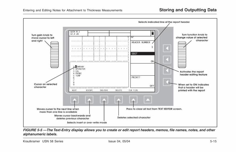
Krautkramer USN 58 Series Issue 04, 05/04 5-15
Krautkramer USN 58 Series Issue 04, 05/04 5-15
Entering and Editing Notes for Attachment to Thickness Measurements Storing and Outputting Data
FIGURE 5-5 —The Text-Entry display allows you to create or edit report headers, memos, file names, notes, and otheralphanumeric labels.
FIGURE 5-5 —The Text-Entry display allows you to create or edit report headers, memos, file names, notes, and otheralphanumeric labels.
Entering and Editing Notes for Attachment to Thickness Measurements Storing and Outputting Data

5-16 Issue 04, 05/04 Krautkramer USN 58 Series
5-16 Issue 04, 05/04 Krautkramer USN 58 Series
Storing and Outputting Data Printing a Report
a file’s notes:
Step 1: Activate the NOTES submenu (in the FILESmenu).
Step 2: Press v twice to set the EDIT function to ON.This allows you to create or edit notes.
Step 3: Note that the bottom of the display screencontains six notes (NOTE A through F). One or morenotes can be created using the USN 58’s Text-Entryfeature (see description in Figure 5-6).
Step 4: Those notes which are attached to specificthickness measurements may be deleted with themeasurement, but cannot be modified once attached.
5.7.1 Including a Notes In a PrintedReport
You can specify whether the Notes attached to theactive data file are listed in a printed report. Thisfunction effects only the list of note letters andcontent. The actual note letter which are attached to
individual data logger thickness measurements will beincluded in the report whenever the thicknessmeasurements are included. To add or remove anactive file’s notes list from the printed report:
Step 1: Activate the NOTES submenu (in the FILESmenu).
Step 2: Press v (two times) next to the PRINT ?function. This will set the vaue to ON which indicatesthat the NOTES will be printed as part of the report.Choosing OFF omits the NOTES listing from thereport.
5.8 Printing a Report
Any data logger or data set file can be output as aprinted report. Reports can also be outputted throughthe serial port to a computer. The contents of a reportare specified by the user. Several features of theactive data file can be omitted from or included in thereport as described below.
Prior to creating a report for output to a printer, see

Krautkramer USN 58 Series Issue 04, 05/04 5-17
Krautkramer USN 58 Series Issue 04, 05/04 5-17
Printing a Report Storing and Outputting Data
FIGURE 5-6—The Text-Entry display allows you to create or edit notes, report headers, memos, file names, and otheralphanumeric labels.
FIGURE 5-6—The Text-Entry display allows you to create or edit notes, report headers, memos, file names, and otheralphanumeric labels.
Printing a Report Storing and Outputting Data

5-18 Issue 04, 05/04 Krautkramer USN 58 Series
5-18 Issue 04, 05/04 Krautkramer USN 58 Series
section 5.9 to designate printer properties andphysically connect to the printer. Prior to creating areport for output to a computer, see section 5.10 toestablish necessary connections.
Step 1: Activate the PRINTER submenu (in the FILESmenu).
Step 2: Press v to select the COPY MODE function.Set this function to REPORT. This outputs a reportwhenever C is pressed.
Step 3: Turn the following features ON or Off toindicate whether or not they should be printed as partof the report (ON) or excluded from the report (OFF).Following each item is a notation that identifies itsmenu location (menu/submenu/function).
• Report Header (FILE / REP HEAD / PRINT ?)
• Notes (FILE / NOTES / PRINT ?)
• Data Logger Thickness Readings (FILE / NOTES /DL PRINT ?)
• Memo (FILE / MEMO / PRINT ?)
• A-Scan (FILE / PRINTER / ASCAN PRINT ?)
• Listing of Data-set or Data-Logger StoredInstrument Settings (FILE / PRINTER / PARAMPRINT ?)
Step 4: Press C to print or output the report.
5.9 Outputting to a Printer
A printer connects to the instrument via the RS-232serial port located at the upper-rear corner of theinstrument. To output data to a specific printer youmust
• Connect the instrument to the printer using thecorrect cable (Serial Printer or Parallel PrinterInterface)
• Configure the instrument to communicate with theattached printer
• Specify what data should be sent to the printer whenC is pressed
Storing and Outputting Data Outputting to a Printer
Storing and Outputting Data Outputting to a Printer
section 5.9 to designate printer properties andphysically connect to the printer. Prior to creating areport for output to a computer, see section 5.10 toestablish necessary connections.
Step 1: Activate the PRINTER submenu (in the FILESmenu).
Step 2: Press v to select the COPY MODE function.Set this function to REPORT. This outputs a reportwhenever C is pressed.
Step 3: Turn the following features ON or Off toindicate whether or not they should be printed as partof the report (ON) or excluded from the report (OFF).Following each item is a notation that identifies itsmenu location (menu/submenu/function).
• Report Header (FILE / REP HEAD / PRINT ?)
• Notes (FILE / NOTES / PRINT ?)
• Data Logger Thickness Readings (FILE / NOTES /DL PRINT ?)
• Memo (FILE / MEMO / PRINT ?)
• A-Scan (FILE / PRINTER / ASCAN PRINT ?)
• Listing of Data-set or Data-Logger StoredInstrument Settings (FILE / PRINTER / PARAMPRINT ?)
Step 4: Press C to print or output the report.
5.9 Outputting to a Printer
A printer connects to the instrument via the RS-232serial port located at the upper-rear corner of theinstrument. To output data to a specific printer youmust
• Connect the instrument to the printer using thecorrect cable (Serial Printer or Parallel PrinterInterface)
• Configure the instrument to communicate with theattached printer
• Specify what data should be sent to the printer whenC is pressed

Krautkramer USN 58 Series Issue 04, 05/04 5-19
Krautkramer USN 58 Series Issue 04, 05/04 5-19
5.9.1 Specifying the Printer Type andBaud Rate
Step 1: Activate the FILES MENU.
Step 2: Select the PRINTER submenu then press vnext to the PRINTER function. Note that the followingprinter options are available:
• EPSON (dot matrix)
• HP LASERJET
• HP DESKJET
• SEIKO DPU-4xx
Step 3: The printer type will remain set to the lastchoice selected.
Step 4: Set the baud rate to match your serial printerby first selecting the SER COMM submenu (still in theFILE menu) by pressing u. Then press v next to theBAUD function until the correct value is chosen.Available baud rates include 300, 600, 1200, 2400,4800, 9600, 19200, 38400, 57600, and 115200. Notethat if you have connected a parallel printer (with a
parallel interface cable) the baud rate must be set tomatch the cable’s requirements.
5.9.2 Setting the COPY Key Function
The user can select one of four actions to be takenwhen C is pressed. Three of these four availableCopy Key actions send data to the RS-232 serial portlocated at the upper-rear corner of the instrument. Toselect the Copy Key action
Step 1: Access the PRINTER Submenu (in the FILESMenu).
Step 2: Activate the COPY MODE function andchoose from the following
• REPORT—The previously specified report contents(see section 5.8) will be sent to the RS-232 port
• PARADUMP—All instrument settings, parameternames, and remote codes will be sent to the RS-232port
Outputting to a Printer Storing and Outputting Data
Outputting to a Printer Storing and Outputting Data
5.9.1 Specifying the Printer Type andBaud Rate
Step 1: Activate the FILES MENU.
Step 2: Select the PRINTER submenu then press vnext to the PRINTER function. Note that the followingprinter options are available:
• EPSON (dot matrix)
• HP LASERJET
• HP DESKJET
• SEIKO DPU-4xx
Step 3: The printer type will remain set to the lastchoice selected.
Step 4: Set the baud rate to match your serial printerby first selecting the SER COMM submenu (still in theFILE menu) by pressing u. Then press v next to theBAUD function until the correct value is chosen.Available baud rates include 300, 600, 1200, 2400,4800, 9600, 19200, 38400, 57600, and 115200. Notethat if you have connected a parallel printer (with a
parallel interface cable) the baud rate must be set tomatch the cable’s requirements.
5.9.2 Setting the COPY Key Function
The user can select one of four actions to be takenwhen C is pressed. Three of these four availableCopy Key actions send data to the RS-232 serial portlocated at the upper-rear corner of the instrument. Toselect the Copy Key action
Step 1: Access the PRINTER Submenu (in the FILESMenu).
Step 2: Activate the COPY MODE function andchoose from the following
• REPORT—The previously specified report contents(see section 5.8) will be sent to the RS-232 port
• PARADUMP—All instrument settings, parameternames, and remote codes will be sent to the RS-232port

5-20 Issue 04, 05/04 Krautkramer USN 58 Series
5-20 Issue 04, 05/04 Krautkramer USN 58 Series
• LOG TO PORT—The value displayed in the LargeDisplay Box (see section 4.8) will be sent to theRS-232 port
• LOG TO FILE—The value displayed in the LargeDisplay Box (but only if it is a thickness value) willbe stored in the active data file. Note that no datawill be sent to the RS-232 port when this action isselected.
Step 3: Pressing C will result in the specified action.
5.10 Outputting to a Computer viathe RS-232 Serial Port
The serial port of a PC can connect with theinstrument via the RS-232 serial port located at theupper-rear corner of the instrument. To output data to aconnected PC you must
• Connect the USN 58 to the PC using the correctcable (RS-232-to-9 Pin Serial Printer Cable)
• Configure the instrument to communicate with theattached PC
• Specify what data should be sent to the PC whenC is pressed (see section 5.9.2)
• Indicate what should be ouput when a Loss of Signal(LOS) occurs.
5.10.1 Specifying the Baud Rate
Step 1: From the HOME MENU, select NEXT thenactivate the GENERAL MENU and the SER COMMsubmenu by pressing u.
Step 2: Then press v next to the BAUD function untilthe baud rate to matches the rate of your softwareapplication. Available baud rates include 300, 600,1200, 2400, 4800, 9600, 19200, 38400, 57600, and115200. Note that if you are using the UltraDOCsoftware utility, you do not need to adjust the baudrate.
5.10.2 Loss of Signal
When the COPY MODE is set to LOG TO PORT, theLOSS OF SIGNAL function affects the value that theinstrument outputs through the serial port whenever C
Storing and Outputting Data Outputting to a Computer via the RS-232 Serial Port
Storing and Outputting Data Outputting to a Computer via the RS-232 Serial Port
• LOG TO PORT—The value displayed in the LargeDisplay Box (see section 4.8) will be sent to theRS-232 port
• LOG TO FILE—The value displayed in the LargeDisplay Box (but only if it is a thickness value) willbe stored in the active data file. Note that no datawill be sent to the RS-232 port when this action isselected.
Step 3: Pressing C will result in the specified action.
5.10 Outputting to a Computer viathe RS-232 Serial Port
The serial port of a PC can connect with theinstrument via the RS-232 serial port located at theupper-rear corner of the instrument. To output data to aconnected PC you must
• Connect the USN 58 to the PC using the correctcable (RS-232-to-9 Pin Serial Printer Cable)
• Configure the instrument to communicate with theattached PC
• Specify what data should be sent to the PC whenC is pressed (see section 5.9.2)
• Indicate what should be ouput when a Loss of Signal(LOS) occurs.
5.10.1 Specifying the Baud Rate
Step 1: From the HOME MENU, select NEXT thenactivate the GENERAL MENU and the SER COMMsubmenu by pressing u.
Step 2: Then press v next to the BAUD function untilthe baud rate to matches the rate of your softwareapplication. Available baud rates include 300, 600,1200, 2400, 4800, 9600, 19200, 38400, 57600, and115200. Note that if you are using the UltraDOCsoftware utility, you do not need to adjust the baudrate.
5.10.2 Loss of Signal
When the COPY MODE is set to LOG TO PORT, theLOSS OF SIGNAL function affects the value that theinstrument outputs through the serial port whenever C

Krautkramer USN 58 Series Issue 04, 05/04 5-21
Krautkramer USN 58 Series Issue 04, 05/04 5-21
is pressed. LOSS OF SIGNAL (located in the SERCOM Menu) may be set to
• ON HIGH—A thickness value of 0.000 istransmitted via the RS-232 port whenever anuncoupled probe condition exists and C is pressed.The analog output is set to high.
• ON LOW—A thickness value of 0.000 is transmittedvia the RS-232 port whenever an uncoupled probecondition exists and C is pressed. The analogoutput is set to low.
• OFF HIGH—The last valid thickness reading istransmitted via the RS-232 port whenever anuncoupled probe condition exists and C is pressed.The analog output is set to high.
• OFF LOW—The last valid thickness reading istransmitted via the RS-232 port whenever anuncoupled probe condition exists and C is pressed.The analog output is set to low.
Changing the LOSS OF SIGNAL setting affects onlythe output via the RS-232 port and has no effect onthe screen’s displayed value.
Outputting to a Computer via the RS-232 Serial Port Storing and Outputting Data
Outputting to a Computer via the RS-232 Serial Port Storing and Outputting Data
is pressed. LOSS OF SIGNAL (located in the SERCOM Menu) may be set to
• ON HIGH—A thickness value of 0.000 istransmitted via the RS-232 port whenever anuncoupled probe condition exists and C is pressed.The analog output is set to high.
• ON LOW—A thickness value of 0.000 is transmittedvia the RS-232 port whenever an uncoupled probecondition exists and C is pressed. The analogoutput is set to low.
• OFF HIGH—The last valid thickness reading istransmitted via the RS-232 port whenever anuncoupled probe condition exists and C is pressed.The analog output is set to high.
• OFF LOW—The last valid thickness reading istransmitted via the RS-232 port whenever anuncoupled probe condition exists and C is pressed.The analog output is set to low.
Changing the LOSS OF SIGNAL setting affects onlythe output via the RS-232 port and has no effect onthe screen’s displayed value.

5-22 Issue 04, 05/04 Krautkramer USN 58 Series
5-22 Issue 04, 05/04 Krautkramer USN 58 Series
THIS PAGE WAS INTENTIONALLY LEFT BLANK.
THIS PAGE WAS INTENTIONALLY LEFT BLANK.

Krautkramer USN 58 Series Issue 04, 05/04 6-1
Krautkramer USN 58 Series Issue 04, 05/04 6-1
Advanced Base-ModelFeatures 6
Advanced Base-ModelFeatures 6

6-2 Issue 04, 05/04 Krautkramer USN 58 Series
6-2 Issue 04, 05/04 Krautkramer USN 58 Series
Advanced Base-Model Features Noise Immunization
In addition to the commonly used features of your USN58, the instrument has several special features usedfor advanced applications or by more advanced users.
This chapter describes these special features andexplains how they are used.
In this chapter, you’ll learn how to:
• Use the Noise Immunization capabilities (section6.1)
• Use the SMART VIEW feature (section 6.2)
• Use the SPARKLE feature (58L only) whichemulates an analog-display screen and BASELINEBREAK, which resolves dynamic echo informationto the baseline (section 6.3)
• Use the AWS D1.1 weld rating feature (section 6.4)
• Reset the instrument and perform other operationswith combined key presses (section 6.5)
6.1 Noise Immunization
TTL outputs can be assigned to any available gate andare set whenever the assigned gate is triggered. Under
normal operation, a TTL is output whenever the firstecho triggers the gate’s logic. When the NOISE IMMNfeatures is activated, the user can determine thenumber of triggering counts required before the TTL isoutput. The user indicates the number of counts, out ofthe total number of counts in an overall “window”,which must trigger the gate before the assigned TTL isoutput. To setup the noise immunization feature followthese steps:
Step 1: Activate the GATES MENU (located in theHOME MENU).
Step 2: With the NSE IMMN submenu selected, pressv next to the ALARM SELECT function. Choose theTTL output to which you wish to apply noiseimmunization.
Step 3: Press v next to the WINDOW function.Continue to press v or turn the function knob to definethe number of counts in the window of examination.Note that if the window size is set to 16 counts (themaximum available) and the count function is set to 4counts, this means that at least 25% (4 ÷16) of allechoes in the window must trigger the gate before theTTL will set.
Advanced Base-Model Features Noise Immunization

Krautkramer USN 58 Series Issue 04, 05/04 6-3
Krautkramer USN 58 Series Issue 04, 05/04 6-3
Advanced Base-Model FeaturesUsing SMART VIEW
Step 4: Press v next to the COUNT function.Continue to press v or turn the function knob toselect the number of counts which must trigger thegate (during the total window period) before the TTL isoutput.
Step 5: When Noise IMMN is activated, the iconwill be displayed.
6.2 Using SMART VIEW
The USN 58 receives many more A-Scan echoes persecond than are displayed (see section 2.3.4 for PRF).In normal operation, the displayed echo is updated ona cycle/time basis. When operating in either SMARTFILLED or HOLLOW mode, the instrument examinesall echoes, acquired since the last display-screenupdate, and displays the one with the most criticalcharacteristics. The instrument determines whichcharacteristics are most critical to the user based onthe user’s choice of parameter in the large display box.For instance, assume the user selects A%A (theamplitude percentage of the echo in gate A) to appearin the large display box, and the instrument is set toone of the SMART modes. The instrument will examine
all the echoes acquired since the last displayed echo.The echo with the highest peak in the A-gate will bedisplayed. To use the SMART VIEW feature:
Step 1: Activate the BASIC MENU (located in theHOME MENU).
Step 2: With the CONFIG submenu selected, press vnext to the ASCAN MODE function. Continue to pressv or turn the function knob to select SMART FILLEDor HOLLOW.
Note that in SMART HOLLOW mode, the A-Scan’sOutline is displayed, while in SMART FILLED mode, afilled A-Scan is displayed.
Step 3: When SMART FILLED or SMART HOLLOW isselected, the icon will be displayed.
H Note:
When SMART FILLED or HOLLOW is activated, andan amplitude reading (A%A, A%B, etc.) is displayed inthe large display box, SMART VIEW will select theA-Scan with the maximum peak to display. When thelarge display box contains a thickness reading(SA/, DA^, etc.) SMART VIEW will select the A-Scanwith the thinnest peak or flank measurement to display.
Advanced Base-Model FeaturesUsing SMART VIEW

6-4 Issue 04, 05/04 Krautkramer USN 58 Series
6-4 Issue 04, 05/04 Krautkramer USN 58 Series
6.3 Using A-Scan EnhancementAnalog Display Emulation
The USN 58 series incorporates break-through featuresthat improve traditional displays. These features areactivated by selecting the A-SCAN ENHANCE functionin the CONFIG submenu.
6.3.1 SPARKLE Intensity Variation(CONFIG/ASCAN ENHANCE/SPARKLE) (58L only)
The built-in SPARKLE feature emulates the intensityvariation traditionally found only with analog displays.
With SPARKLE’s intensity variation, the A-Scan displaycan now indicate acoustic phenomena not apparentwith conventional digital displays. Figure 6-1 illustratesthe intensity variation visible in a SPARKLE A-Scan.
6.3.2 Baseline Break (CONFIG/A-SCANENHANCE/BASELINE BREAK)
This feature, shown in Figure 6-2, details acousticphenomena and is available in all USN 58 instruments.BASELINE BREAK extends down to the displaybaseline each point on the A-Scan which represents anon-continuous location on the acoustic signal.
Advanced Base-Model Features Using A-Scan Enhancement Analog Display Emulation

Krautkramer USN 58 Series Issue 04, 05/04 6-5
Krautkramer USN 58 Series Issue 04, 05/04 6-5
FIGURE 6-1—The SPARKLE feature emulates an analog display byoffering varied A-Scan intensity.
FIGURE 6-1—The SPARKLE feature emulates an analog display byoffering varied A-Scan intensity.
Advanced Base-Model Features Using A-Scan Enhancement Analog Display Emulation
Advanced Base-Model Features Using A-Scan Enhancement Analog Display Emulation

6-6 Issue 04, 05/04 Krautkramer USN 58 Series
6-6 Issue 04, 05/04 Krautkramer USN 58 Series
Advanced Base-Model FeaturesUsing A-Scan Enhancement Analog Display Emulation
FIGURE 6-2—Baseline Break
FIGURE 6-2—Baseline Break
Advanced Base-Model FeaturesUsing A-Scan Enhancement Analog Display Emulation

Krautkramer USN 58 Series Issue 04, 05/04 6-7
Krautkramer USN 58 Series Issue 04, 05/04 6-7
6.4 AWS D1.1 Weld RatingFeature
This feature allows analysis of welds according toAWS specification D1.1 and provides a D1.1 rating.The AWS D1.1 feature is accessed via the TRIG Menu.The feature utilizes four AWS-specified variablesincluding:
A INDICATION—Gain (in dB) required to position anA-Scan echo’s peak (from the measured reflector) atan amplitude equal to the reference amplitude (between20 and 90% of full screen height)
B REFERENCE—Gain (in dB) required to position an A-Scan echo’s peak (from the reference reflector) at theuser-selected amplitude (between 20 and 90% of FSH)
C ATTENUATION—Determined by subtracting 1 inchfrom the sound-path distance to the discontinuity,using the equation: C = (SA-1) × 2. This compensatesfor sound loss from material attenuation along thesound path to the discontinuity.
D D1.1 RATING—Calculated based on the AWSformula: D = A-B-C (See NOTE)
Advanced Base-Model Features AWS D1.1 Weld Rating Feature
H Note:
The dB value of A-Indication will be automaticallyadjusted to match the amplitude of the B-Ref uponperforming the dB rating calculation.
Before activating the AWS D1.1 weld rating feature, besure that all instrument settings are properly adjustedfor the specific measurement application. Then accessthe AWS D1.1 Submenu (via the TRIG Menu) andfollow this procedure:
Step 1: Apply couplant and couple the probe to asuitable reference test standard.
Step 2: Ensure that the A-Gate is positioned over thedesired echo. Then adjust the gain until the peak of thedesired reference echo reaches the desired amplitudeas shown in Figure 6-3. Note that if the echo’s peakamplitude (A%A) does not fall between 20% and 90%,the inputted point will not be accepted.
Step 3: Press v next to the B REFERENCE function(then h to confirm) to define the reference dB level.
6.4 AWS D1.1 Weld RatingFeature
This feature allows analysis of welds according toAWS specification D1.1 and provides a D1.1 rating.The AWS D1.1 feature is accessed via the TRIG Menu.The feature utilizes four AWS-specified variablesincluding:
A INDICATION—Gain (in dB) required to position anA-Scan echo’s peak (from the measured reflector) atan amplitude equal to the reference amplitude (between20 and 90% of full screen height)
B REFERENCE—Gain (in dB) required to position an A-Scan echo’s peak (from the reference reflector) at theuser-selected amplitude (between 20 and 90% of FSH)
C ATTENUATION—Determined by subtracting 1 inchfrom the sound-path distance to the discontinuity,using the equation: C = (SA-1) × 2. This compensatesfor sound loss from material attenuation along thesound path to the discontinuity.
D D1.1 RATING—Calculated based on the AWSformula: D = A-B-C (See NOTE)
H Note:
The dB value of A-Indication will be automaticallyadjusted to match the amplitude of the B-Ref uponperforming the dB rating calculation.
Before activating the AWS D1.1 weld rating feature, besure that all instrument settings are properly adjustedfor the specific measurement application. Then accessthe AWS D1.1 Submenu (via the TRIG Menu) andfollow this procedure:
Step 1: Apply couplant and couple the probe to asuitable reference test standard.
Step 2: Ensure that the A-Gate is positioned over thedesired echo. Then adjust the gain until the peak of thedesired reference echo reaches the desired amplitudeas shown in Figure 6-3. Note that if the echo’s peakamplitude (A%A) does not fall between 20% and 90%,the inputted point will not be accepted.
Step 3: Press v next to the B REFERENCE function(then h to confirm) to define the reference dB level.
Advanced Base-Model Features AWS D1.1 Weld Rating Feature

6-8 Issue 04, 05/04 Krautkramer USN 58 Series
6-8 Issue 04, 05/04 Krautkramer USN 58 Series
Advanced Base-Model FeaturesAWS D1.1 Weld Rating Feature
FIGURE 6-3—After adjusting the gain so that the reference echo’s peak is at the desired amplitude, record thereference dB. This reference dB value will be stored in the instrument until manually changed.
FIGURE 6-3—After adjusting the gain so that the reference echo’s peak is at the desired amplitude, record thereference dB. This reference dB value will be stored in the instrument until manually changed.
Advanced Base-Model FeaturesAWS D1.1 Weld Rating Feature

Krautkramer USN 58 Series Issue 04, 05/04 6-9
Krautkramer USN 58 Series Issue 04, 05/04 6-9
Advanced Base-Model Features Resetting the Instrument
H Note:
Storing an AWS reference will automatically switch thevalue of the AWS MODE function (located in thePOSITION Submenu of the TRIG Menu) to ON. WhileAWS MODE is ON, two measurement result boxes willbe automatically set (if not already configured) todisplay SA and A%A values. These result selectionswill remain locked until AWS MODE is turned OFF.
Step 4: To evaluate a reflector in a test piece, couplethe probe to the test piece and press u to select thePOSITION Submenu as shown in Figure 6-4. Nowadjust the A-Gate position so that it is over the desiredecho.
Step 5: Adjust the gain until the peak of the test-piece’s echo reaches the desired screen height asshown in Figure 6-4.
H Note:
The dB value that is recorded for A-Indication will beautomatically adjusted based upon the amplitudedifference between it and the value recorded for B-REF.It will usually NOT match the instrument‘s dB gainsetting.
Step 6: Return to the AWS D1.1 Submenu and pressv next to the A INDICATION function. This will recordthe adjusted dB setting and will automatically calculateand display values for the AWS variables C and D asshown in Figure 6-5. Rating D can then be applied tothe appropriate acceptance criteria found in AWS D1.1.
To evaluate additional reflectors against the recordedreference, simply repeat Steps 4 to 6.
6.5 Resetting the Instrument
The instrument can be reset, in one of two ways, byusing a combination of key presses.
To reset the instrument settings WITHOUT deleting allstored data files, turn the instrument on by pressingand holding K and C simultaneously. Hold bothbuttons until the startup cycle is complete.
H Note:
Storing an AWS reference will automatically switch thevalue of the AWS MODE function (located in thePOSITION Submenu of the TRIG Menu) to ON. WhileAWS MODE is ON, two measurement result boxes willbe automatically set (if not already configured) todisplay SA and A%A values. These result selectionswill remain locked until AWS MODE is turned OFF.
Step 4: To evaluate a reflector in a test piece, couplethe probe to the test piece and press u to select thePOSITION Submenu as shown in Figure 6-4. Nowadjust the A-Gate position so that it is over the desiredecho.
Step 5: Adjust the gain until the peak of the test-piece’s echo reaches the desired screen height asshown in Figure 6-4.
H Note:
The dB value that is recorded for A-Indication will beautomatically adjusted based upon the amplitudedifference between it and the value recorded for B-REF.It will usually NOT match the instrument‘s dB gainsetting.
Step 6: Return to the AWS D1.1 Submenu and pressv next to the A INDICATION function. This will recordthe adjusted dB setting and will automatically calculateand display values for the AWS variables C and D asshown in Figure 6-5. Rating D can then be applied tothe appropriate acceptance criteria found in AWS D1.1.
To evaluate additional reflectors against the recordedreference, simply repeat Steps 4 to 6.
6.5 Resetting the Instrument
The instrument can be reset, in one of two ways, byusing a combination of key presses.
To reset the instrument settings WITHOUT deleting allstored data files, turn the instrument on by pressingand holding K and C simultaneously. Hold bothbuttons until the startup cycle is complete.
Advanced Base-Model Features Resetting the Instrument

6-10 Issue 04, 05/04 Krautkramer USN 58 Series
6-10 Issue 04, 05/04 Krautkramer USN 58 Series
Advanced Base-Model FeaturesAWS D1.1 Weld Rating Feature
FIGURE 6-4—Position the A-Gate so that it is over the desired echo.
FIGURE 6-4—Position the A-Gate so that it is over the desired echo.
Advanced Base-Model FeaturesAWS D1.1 Weld Rating Feature
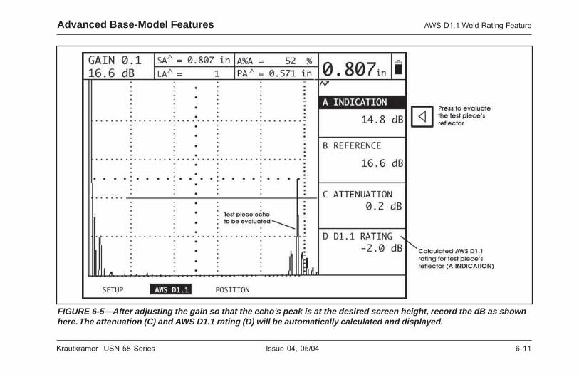
Krautkramer USN 58 Series Issue 04, 05/04 6-11
Krautkramer USN 58 Series Issue 04, 05/04 6-11
Advanced Base-Model Features AWS D1.1 Weld Rating Feature
FIGURE 6-5—After adjusting the gain so that the echo’s peak is at the desired screen height, record the dB as shownhere. The attenuation (C) and AWS D1.1 rating (D) will be automatically calculated and displayed.
FIGURE 6-5—After adjusting the gain so that the echo’s peak is at the desired screen height, record the dB as shownhere. The attenuation (C) and AWS D1.1 rating (D) will be automatically calculated and displayed.
Advanced Base-Model Features AWS D1.1 Weld Rating Feature

6-12 Issue 04, 05/04 Krautkramer USN 58 Series
6-12 Issue 04, 05/04 Krautkramer USN 58 Series
To reset the instrument settings and DELETE all storeddata files, turn the instrument on by pressing andholding K and X simultaneously. Hold both buttonsuntil the startup cycle is complete.
H Note:
When the instrument has been reset, the settings arereturned to the default values and data files (whenapplicable) are deleted. The effects of resetting theinstrument may not be reversed.
Advanced Base-Model FeaturesAWS D1.1 Weld Rating Feature
Advanced Base-Model FeaturesAWS D1.1 Weld Rating Feature

Krautkramer USN 58 Series Issue 04, 05/04 7-1
Krautkramer USN 58 Series Issue 04, 05/04 7-1
I/O Ports Technical Data 7
I/O Ports Technical Data 7

7-2 Issue 04, 05/04 Krautkramer USN 58 Series
7-2 Issue 04, 05/04 Krautkramer USN 58 Series
I/O Ports Technical Data Sending Readings to Other Devices
7.1 Sending Readings to OtherDevices
Digital measurements displayed in the Large DisplayBox can be transmitted via the RS-232 I/O port to anycompatible device, such as a personal computer,printer, or other RS-232 recording instrument.
In all cases, the correct cable will be required. Contactyour nearest Krautkramer representative.
To output the measurement value displayed in the largedisplay box
1. Connect the instrument’s RS-232 Port to theexternal device with the correct cable
2. Set the COPY MODE to LOG TO PORT.
3. Press C to output the measurement value in thelarge display box.
Table 7-1 shows single-reading formats ofmeasurement values transmitted by the USN 58.Specific format depends on the unit of measure andthe measurement resolution.
1-7elbaT
stamroFgnidaeRelgniS
#etyB NIXXX.X NIXX.XX MMXX.XX MMX.XXX
1 ecapS ecapS ecapS ecapS
2 tigiD tigiD tigiD tigiD
3 .P.D tigiD tigiD tigiD
4 tigiD .P.D .P.D tigiD
5 tigiD tigiD tigiD .P.D
6 tigiD tigiD tigiD tigiD
7 ecapS ecapS ecapS ecapS
8 I I M M
9 N N M M
01 ecapS ecapS ecapS ecapS
11 ecapS ecapS ecapS ecapS
21 RC RC RC RC
31 FL FL FL FL
deeFeniL:FL;nruteRegairraC:RC;tnioPlamiceD:.P.D
I/O Ports Technical Data Sending Readings to Other Devices

Krautkramer USN 58 Series Issue 04, 05/04 7-3
Krautkramer USN 58 Series Issue 04, 05/04 7-3
I/O Ports Technical DataAnalog Output
7.2 Analog Output
H Note:
The OUTPUT DELAY function (located in the ALARMSubmenu of the GATES Menu) allows you to specifythe number of PRF Cycles (0, 1, 2, or 3) delay toimpose on all analog and TTL outputs that passthrough the Real-time I/O Connector.
Amplitude and time of flight (distance) analog outputsare provided via the 15-pin Real-time I/O Connectorshown in Figure 7-1.
1. External Trigger—The rising edge of this signalcauses the USN 58 to begin a new cycle. Thepulser will fire 35 ns (+0 to 20 ns) after the risingedge of External Trigger. The minimum high periodfor External Trigger is 40 ns, there is no maximumhigh period, but the signal must be low for at least166.6 microseconds before any sub-sequentrising edge. Note: PRF Mode must be set toEXTERNAL for the trigger to be recognized.
2. Data Out Inhibit—The rising edge of this signalwill cause all outputs to become inactive (TTL’sgo low and Analog Outputs are set to 0 V)
3. Reset Alarm—The rising edge of this signal willreset the TTL outputs to a low level when ‘latched’has been selected for TTL mode.
4-7 Analog Outputs—these pins will output a voltageproportional to the values selected for readingboxes 1-4. When an amplitude is selected for areading a 0 V output indicates a 0% fsh signaland a 2.5 output indicates a 100% fsh signal.When a thickness value is selected for a readinga 0 V output corresponds to a thickness valuethat is less than or equal to the left edge of thedisplayed screen (0% horizontal) and a 2.5 outputcorresponds to a thickness value that is greaterthan or equal to the value at 100% horizontal ofthe displayed screen.
8. Data Valid—this signal is generated once percycle. During the “high” portion of the signal theTTL and Analog Outputs are being updated andare not valid. The falling edge of this signal or alow level on this signal indicate that data is validand stable. (See Figure 7-2)
I/O Ports Technical DataAnalog Output

7-4 Issue 04, 05/04 Krautkramer USN 58 Series
7-4 Issue 04, 05/04 Krautkramer USN 58 Series
I/O Ports Technical Data Analog Output
FIGURE 7-1—Real time I/O connector
FIGURE 7-1—Real time I/O connector
I/O Ports Technical Data Analog Output

Krautkramer USN 58 Series Issue 04, 05/04 7-5
Krautkramer USN 58 Series Issue 04, 05/04 7-5
9-11 TTL Outputs—These pins output a level whichindicate the alarm state of the selectedparameter. When an alarm condition exist theoutput is “ high” (5 V) and when no alarm existsthe output is “low” (0 V).
12. Ground—
13. SAP Out—this pin outputs a 50 microsecondslong pulse at the beginning of each cycle. Thepulser fires 35 microseconds after the rising edgeof this signal. (See Figure 7-2)
14. MUXD Ascan Enable—this pin accepts a signalfrom the Krautkramer MUXD multiscanner. Thissignal indicates the channel from the MUXDwhich should be selected for display on theUSN 58.
I/O Ports Technical DataAnalog Output
FIGURE 7-2—Data Valid Signal
9-11 TTL Outputs—These pins output a level whichindicate the alarm state of the selectedparameter. When an alarm condition exist theoutput is “ high” (5 V) and when no alarm existsthe output is “low” (0 V).
12. Ground—
13. SAP Out—this pin outputs a 50 microsecondslong pulse at the beginning of each cycle. Thepulser fires 35 microseconds after the rising edgeof this signal. (See Figure 7-2)
14. MUXD Ascan Enable—this pin accepts a signalfrom the Krautkramer MUXD multiscanner. Thissignal indicates the channel from the MUXDwhich should be selected for display on theUSN 58.
FIGURE 7-2—Data Valid Signal
I/O Ports Technical DataAnalog Output

7-6 Issue 04, 05/04 Krautkramer USN 58 Series
7-6 Issue 04, 05/04 Krautkramer USN 58 Series
7.3 Remote Control of theUSN 58
The USN 58 is capable of receiving coded instructionsfrom a personal computer or terminal connected to theRS-232 I/O port.
Instructions must be transmitted to the USN 58 asescape sequences, that is, a series of keystrokes, thefirst of which is always the Escape key (ASCII 27).The Escape key will be identified in this manual as[Esc].
Every key press and menu function of the USN 58 canbe operated by remote control. In addition, the currentvalue (setting) of a particular function may berequested.
This section provides general instructions on commandsequence format. Function codes, along with thevalues for the options associated with the functions,are provided in tables in this section.
To execute a keypad operation or adjust the setting ofa menu function, transmit the required escape
sequence using the format below. Refer to the tableslater in this section for the 2 digit code, acceptablevalue range, and resolution.
<<[Esc]>><<Code>><<Space>><<Value>><<[Return]>>
[Esc] = Escape Key - CHR$(27)
Code = 2 digit code from the table
Space = Space bar
Value = Desired value from the tables
[Return] Enter key - CHR$(13)
Values must be entered as a multiple of the resolutionshown in the table for each function. As an example,the following sequence would adjust the range of theUSN 60 to 5.000 inches:
<<[Esc]>><<DW>><<Space>><<5.000>><<[Return]>>
To request the following status, or value, of anyfunction, use the following sequence:
<<[Escape]>><<AT>><<[Return]>>
I/O Ports Technical Data Remote Control of the USN 58

Krautkramer USN 58 Series Issue 04, 05/04 7-7
Krautkramer USN 58 Series Issue 04, 05/04 7-7
The unit will answer with the threshold value,expressed as a multiple of the resolution shown in thetable. In this case, a response or 40 would indicate athreshold level of 40%, because the resolution is 1.
Commands can be sent using either a user writtenprogram, or a commercially available serialcommunications program. There are many suchinexpensive programs for terminal and moderncommunications.
H Note:
The instrument will make no response to a commanduntil <[Return]> is input.
The tables in this section show all functions, theirrelated codes, values and resolution. An explanationsof table organization and content follows.
All functions are listed in Table 7-2 by the names thatappear in the menus.
Keypad controls are also listed alphabetically in thesame tables.
“Code” is the 2 digit code to activate the particularfunction, as explained earlier in this section.
“Range” is either the adjustment range of the functionor a list options. In either case, values from the Rangecolumn are used in the “Value Portion” of the escapesequence.
‘Resolution’ specifies the smallest increment forchoosing the value above.
7.4 Remote Codes for theUSN 58
It is possible to set or read any parameter in theinstrument over the serial communication port. To reador set the value of any parameter the followinginstructions must be followed.
To read the value of a parameter the followingcommand string should be sent to the instrument:
<ESC>XX<RETURN> . where XX is the remote codeof the desired parameter
I/O Ports Technical DataRemote Codes for the USN 58

7-8 Issue 04, 05/04 Krautkramer USN 58 Series
7-8 Issue 04, 05/04 Krautkramer USN 58 Series
The instrument will return the following (providedECHO mode is ON):
*XX<SPACE>YYY<RETURN> Where XX is theremote code and YYY is the setting / value
To set the value of a parameter the following commandstring should be sent to the instrument:
<ESC>XX<SPACE>YYY<RETURN> Where XX isthe remote code and YYY is the setting / value
The instrument will return the following (providedECHO mode is ON):
*XX<SPACE>YYY<RETURN> Where XX is theremote code and YYY is the setting / value
Table 7-2 summarizes the remote codes and allowablesettings for all of the parameters.
I/O Ports Technical Data Remote Codes for the USN 58
The instrument will return the following (providedECHO mode is ON):
*XX<SPACE>YYY<RETURN> Where XX is theremote code and YYY is the setting / value
To set the value of a parameter the following commandstring should be sent to the instrument:
<ESC>XX<SPACE>YYY<RETURN> Where XX isthe remote code and YYY is the setting / value
The instrument will return the following (providedECHO mode is ON):
*XX<SPACE>YYY<RETURN> Where XX is theremote code and YYY is the setting / value
Table 7-2 summarizes the remote codes and allowablesettings for all of the parameters.
I/O Ports Technical Data Remote Codes for the USN 58
H Note:
The state of the ECHO mode (see the end of Table 7-2)determines what information will be returned by theinstrument to the connected computer. If ECHO mode(8L) is set to ON, entered command characters and (ifapplicable) settings will be returned by the instrumentto the connected computer as soon as <[Return]> isinput. If ECHO mode is set to OFF, only requesteddata will be returned to the connected computer.

Krautkramer USN 58 Series Issue 04, 05/04 7-9
Krautkramer USN 58 Series Issue 04, 05/04 7-9
I/O Ports Technical DataRemote Codes for the USN 58
2-7elbaT
sedoCetomeR
RETEMARAP ETOMEREDOC
SGNITTES RETEMARAP EDOCETOMER SGNITTES
?tnirPnacsA ?A FFO:0NO:1
htdiWAetaG WA .ni0.084—.ni010.0M91.21—mm52.0
CGAAetaG AA FFO:0NO:1
DETNEMELPMITON
teseRmralA XA STESER:1)ylnOetirW(
)L85(geLroloC CA FFO:0nacS-A:1
dirG:2
CGABetaG AB FFO:0NO:1
DETNEMELPMITONtratSAetaG DA .ni0.084—.ni000.0
M91.21—mm00.0tratSBetaG DB .ni0.084—.ni000.0
M91.21—mm00.0ecnahnEnacsA EA ENON:0
)L85(ELKRAPS:1KAERBENILESAB:2
)L85(KRBESAB&ELKRAPS:3
niaGllawkcaB GB Bd0.011ot0.0
nroH HA ELBASID:0ELBANE:1
thgiLkcaB LB FFO:0NO:1
edoMLTT LA ces52.DEMIT:0ces05.DEMIT:1ces0.1DEMIT:2ces0.2DEMIT.3
SUOENATNATSNI:4DEHCTAL:5
cigoLBetaG MB FFO:0EVITISOP:1EVITAGEN:2ERUSAEM:3
cigoLAetaG MA FFO:0EVITISOP:1EVITAGEN:2ERUSAEM:3
edoMllawkcaB OB FFO:0NO:1
noitaunettAfeRSGD RA .ni/Bd045.2—0m/Bd0.001—0
etaRduaB RB 0021:00042:10084:20069:3
00291:400483:500675:6002511:7
edoMtratSAetaG SA PI:0FI:1
edoMtratSBetaG SB PI:0FI:1
1#ETAG:2dlohserhTAetaG TA %1fospets/09ot5 dlohserhTBetaG TB %1fospets/09ot5
noitcerroCedutilpmASGD VA Bd0.02otBd0.02- htdiWBetaG WB .ni0.084—.ni010.0M91.21—mm52.0
I/O Ports Technical DataRemote Codes for the USN 58
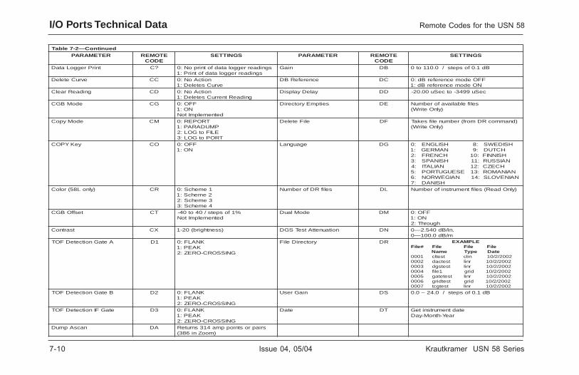
7-10 Issue 04, 05/04 Krautkramer USN 58 Series
7-10 Issue 04, 05/04 Krautkramer USN 58 Series
I/O Ports Technical Data Remote Codes for the USN 58
deunitnoC—2-7elbaT
RETEMARAP ETOMEREDOC
SGNITTES RETEMARAP ETOMEREDOC
SGNITTES
tnirPreggoLataD ?C sgnidaerreggolatadfotnirpoN:0sgnidaerreggolatadfotnirP:1
niaG BD Bd1.0fospets/0.011ot0
evruCeteleD CC noitcAoN:0evruCseteleD:1
ecnerefeRBD CD FFOedomecnereferBd:0NOedomecnereferBd:1
gnidaeRraelC DC noitcAoN:0gnidaeRtnerruCseteleD:1
yaleDyalpsiD DD ceSu9943-otceSu00.02-
edoMBGC GC FFO:0NO:1
detnemelpmItoN
seitpmEyrotceriD ED selifelbaliavaforebmuN)ylnOetirW(
edoMypoC MC TROPER:0PMUDARAP:1ELIFotGOL:2
TROPotGOL:3
eliFeteleD FD )dnammocRDmorf(rebmunelifsekaT)ylnOetirW(
yeKYPOC OC FFO:0NO:1
egaugnaL GD HSIDEWS:8HSILGNE:0HCTUD:9NAMREG:1HSINNIF:01HCNERF:2
NAISSUR:11HSINAPS:3HCEZC:21NAILATI:4
NAINAMOR:31ESEUGUTROP:5NAINEVOLS:41NAIGEWRON:6
HSINAD:7)ylnoL85(roloC RC 1emehcS:0
2emehcS:13emehcS:24emehcS:3
selifRDforebmuN LD )ylnOdaeR(seliftnemurtsniforebmuN
tesffOBGC TC %1fospets/04ot04-detnemelpmItoN
edoMlauD MD FFO:0NO:1
hguorhT:2tsartnoC XC )ssenthgirb(02-1 noitaunettAtseTSGD ND .ni/Bd045.2—0
m/Bd0.001—0AetaGnoitceteDFOT 1D KNALF:0
KAEP:1GNISSORC-OREZ:2
yrotceriDeliF RD ELPMAXEeliFeliFeliF#eliF
etaDepyTemaN2002/2/01nilctsetlc10002002/2/01rniltsetcad20002002/2/01rniltsetsgd30002002/2/01dirg1elif40002002/2/01rniltsetetag50002002/2/01dirgtsetdirg60002002/2/01rniltsetgct7000
BetaGnoitceteDFOT 2D KNALF:0KAEP:1
GNISSORC-OREZ:2
niaGresU SD Bd1.0fospets/0.42–0.0
etaGFInoitceteDFOT 3D KNALF:0KAEP:1
GNISSORC-OREZ:2
etaD TD etadtnemurtsniteGraeY-htnoM-yaD
nacsApmuD AD sriaprostnioppma413snruteR)mooZni683(
I/O Ports Technical Data Remote Codes for the USN 58

Krautkramer USN 58 Series Issue 04, 05/04 7-11
Krautkramer USN 58 Series Issue 04, 05/04 7-11
I/O Ports Technical DataRemote Codes for the USN 58
deunitnoC—2-7elbaT
RETEMARAP ETOMEREDOC
SGNITTES RETEMARAP ETOMEREDOC
SGNITTES
yticoleVyaleDSGD VD ceSu/ni9926.0—ceSu/ni8900.0ceS/M00061—ceS/M052
noitamrofnIredaeH IH 61otpugnirtsretcarahCsretcarahc
egnaR WD .ni0.084—.ni040.0M91.21—mm00.1
timiLhgiH LH .ni0.084—.ni0.0M91.21—mm0.0
tluseRetaulavE RE )Bdro%(evruCotpmA:0)eziS.feR.viuqE(SRE:1
yeKEMOH MH FFO:0NO:1
evruCSGD SE .aiD.ffEs'eborpot.ni210.0morF.aiD.ffEs'eborpotmm03.0morF
edoMssenkcihT RH LAMRON:0NOITULOSER-HGIH:1
NOISICERP:2detnemelpmItoN
evruCGCThsiniF HF sretemarapoN)ylnOetirW(
edoMtuptuOdeepShgiH SH enoN:000675tatuO:1
009511tatuO:2edoMyalpsiDnacsA IF WOLLOH:0
DELLIF:1WOLLOHTRAMS:2
DELLIFTRAMS:3
eltiTredaeH TH 61otpugnirtsretcarahCsretcarahc
emaNeliF NF stesroemaneliftnerrucsnruteRemandettupniehtoteliftnerruc
)sretcarahc41otpu()stsixetifi(
CGAFI AI FFO:0NO:1
detnemelpmItoNycneuqerF RF zHM1:0
zHM2:1zHM52.2:2
zHM4:3zHM5:4zHM01:5zHM51:6
PLzHM52.2–52.:7PHzHM52–01:8
BBzHM52–2:9
noitarugifnoCtnemurtsnI CI seludomdellatsnifotsilsnruteR
eliFtimsnarT XF RDmorf(rebmunelifseriuqeR)ylnOdaeR()dnammoc
noitacifitnedItnemurtsnI DI R85NSUroL85NSUsnruteR
yeKezeerF ZF FFO:0NO:1
cigoLetaGFI MI FFO:0EVITISOP:1EVITAGEN:2ERUSAEM:3
daolpUeliF UF XFhtiwdeilppussa(elifsekaT)dnammoc
tratSetaGFI SI .ni0.084—.ni000.0M91.21—mm00.0
elucitarG RG FFO:0%02:1%01:2
dlohserhTetaGFI TI %1fospets/09ot5
tceleSetaG SG 1#ETAG:02#ETAG:1
ETAGFI:2
htdiWetaGFI WI .ni0.084—.ni010.0M91.21—mm00.0
#redaeH #H 1fospets/01ot1 roloCSIJ CJ detnemelpmItoN?tnirPredaeH ?H FFO:0
NO:1yreuQeludoM HJ gnitneserperdrowlamiceD
ottrevnoC.seludomdellatsnifidellatsnieludoM;lamicedaxeh
.tessitiBeludoMGCT—0tiBeludoMSGD—1tiB
eludoMSIJ—2tiBeludoMBGC—3tiB
eludoMetaGFI—4tiBeludoMssenkcihTnoisicerP—5tiBeludoMrotaunettAllawkcaB—6tiB
eludoMliaR—7tiBeludoMyticoleVotuA—8tiB
eludoMtuptuOdeepShgiH—9tiByeKpleH EH FFO:0
NO:1edoMSIJ MJ detnemelpmItoN
I/O Ports Technical DataRemote Codes for the USN 58

7-12 Issue 04, 05/04 Krautkramer USN 58 Series
7-12 Issue 04, 05/04 Krautkramer USN 58 Series
Remote Codes for the USN 58I/O Ports Technical Data
deunitnoC—2-7elbaT
RETEMARAP ETOMEREDOC
SGNITTES RETEMARAP EDOCETOMER SGNITTES
tesffOSIJ OJ detnemelpmItoNevruCSIJ VJ detnemelpmItoN ?tnirPomeM ?M FFO:0
NO:1pUbonKniaG 1K .kcilcenopubonKniaGsnruT
)retemaraPoN,ylnOetirW(1#yeKUNEM 1M FFO:0
NO:1nwoDbonKniaG 2K .kcilcenonwodbonKniaGsnruT
)retemaraPoN,ylnOetirW(2#yeKUNEM 2M FFO:0
NO:1pUbonKnoitcnuF 3K .kcilcenopubonKnoitcnuFsnruT
)retemaraPoN,ylnOetirW(3#yeKUNEM 3M FFO:0
NO:1nwoDbonKnoitcnuF 4K .kcilcenonwodbonKnoitcnuFsnruT
)retemaraPoN,ylnOetirW(4#yeKUNEM 4M FFO:0
NO:1ecnerefeRkcihT RK .ni0.084—.ni000.0
M91.21—mm00.05#yeKUNEM 5M FFO:0
NO:1etatS1DEL 1L .1DELfoetatSstropeR
FFO:0NO:1
)retemarapoN,ylnOdaeR(
6#yeKUNEM 6M FFO:0NO:1
etatS2DEL 2L .2DELfoetatSstropeRFFO:0
NO:1)retemarapoN,ylnOdaeR(
noitacifingaM AM noitacifingaMoN:0noitacifingaM:1
etatS3DEL 3L .3DELfoetatSstropeRFFO:0
NO:1)retemarapoN,ylnOdaeR(
edoMSGD DM FFO:0NO:1
yalpsiDrahCegraL CL FFO:01#gnidaeR:12#gnidaeR:23#gnidaeR:34#gnidaeR:4
etaGyfingaM GM 1#ETAG:02#ETAG:1
ETAGFI:2
)ylnoL85(yeKkcoL KL FFO:0NO:1
edoMyaleDFI IM tcatnoC:0noisremmI:1
timiLwoL LL .ni0.084—.ni0.0M91.21—mm0.0
kcoLretsaM LM FFO:0NO:1
edoMlangiSfossoL OL FFO:0NO:1
omeM OM gnirts#OM>cse<7-1=#
)rebmunenilomem(pu=gnirts
sretcarahc63noitcerroCrefsnarTSGD SL Bd0.03—Bd0.03- epyTtnemerusaeM TM FPI:0
FFI:1TLUM:2
detnemelpmItoN
Remote Codes for the USN 58I/O Ports Technical Data

Krautkramer USN 58 Series Issue 04, 05/04 7-13
Krautkramer USN 58 Series Issue 04, 05/04 7-13
deunitnoC—2-7elbaT
RETEMARAP EDOCETOMER SGNITTES RETEMARAP EDOCETOMER SGNITTES
lairetaM VM lairetammotsuC:0edixOLA:1
)raehS(edixOLA:2munimulA:3
)raehS(munimulA:4muillyreB:5
)raehS(muillyreB:6ssarB:7
)raehS(ssarB:8muimdaC:9
)raehS(muimdaC:01reppoC:11
)raehS(reppoC:21)nworc(ssalG:31
)raehS()nworc(ssalG:41nirecylG:51
dloG:61ecI:71
)raehS(ecI:81lenocnI:91
)raehS(lenocnI:02norI:12
)raehS(norI:22)tsac(norI:32
)raehS()tsac(norI:42daeL:52
muisengaM:62)raehS(muisengaM:72
yrucreM:82munedbyloM:92
)raehS(munedbyloM:03lenoM:13
)raehS(lenoM:23
lairetaM VM enerpoeN:33lekciN:43
)raehS(lekciN:536-6,nolyN:63
)03-EAS(liO:73munitalP:83
)raehS(munitalP:93ssalgixelP:04
enelyhteyloP:14enerytsyloP:24
enahteruyloP:34ztrauQ:44
)raehS(ztrauQ:54lytuB,rebbuR:64
revliS:74)raehS(revliS:84
dlim,leetS:94)raehS(dlim,leetS:05
sselniats,leetS:15)raehS(sselniats,leetS:25
nolfeT:35niT:45
)raehS(niT:55muinatiT:65
)raehS(muinatiT:75netsgnuT:85
)raehS(netsgnuT:95muinarU:06
)raehS(muinarU:16retaW:26
cniZ:36)raehS(cniZ:46
muinocriZ:56
I/O Ports Technical DataRemote Codes for the USN 58

7-14 Issue 04, 05/04 Krautkramer USN 58 Series
7-14 Issue 04, 05/04 Krautkramer USN 58 Series
deunitnoC—2-7elbaT
RETEMARAP EDOCETOMER SGNITTES RETEMARAP EDOCETOMER SGNITTES
#etoN #N 1fospets/6ot1 1#yeKRETEMARAP 1P FFO:0NO:1
?tnirPetoN ?N FFO:0NO:1
2#yeKRETEMARAP 2P FFO:0NO:1
tnuoCesioN CN 61hguorht1 3#yeKRETEMARAP 3P FFO:0NO:1
etoN ON gnirts#OM>cse<6-1=#
)rebmuneton(pu=gnirts
sretcarahc61
4#yeKRETEMARAP 4P FFO:0NO:1
)laCotuA(ecnerefeRnihT RN .ni0.084—.ni000.0M91.21—mm00.0
elgnAeborP AP 1.0FOspets/09ot0
tceleSmralA SN 1LTT:02LTT:13LTT:2
edoMezeerF CP LLA:0KAEP:1
ERAPMOC:2ceS5.EPOLEVNE:3ceS1EPOLEVNE:4ceS2EPOLEVNE:5KAEPEPOLEVNE:6
wodniWesioN WN 61hguorht1 yaleDeborP DP ceSu7999.999—0000.0
retemaiD-O DO mm0183roni0.051otpUeborpnosdnepedtimilwoL
ssenkcihttrap,elgna
edoMFRP FP WOLOTUA:0HGIHOTUA:1
LAUNAM:2LANRETXE:3
TESFFOFI FO 7999.999—ceS/u7999.999-ceS/u
gnipmaD GP mhO05-0mho57-1
mho051-2edoMnoitarepO MO detnemelpmItoN ygrenE IP WOL:0
HGIH:1etatSlangiSfossoL SO SOL/wwoLtuptuOgolanA:0
SOL/whgIHtuptuOgolanA:1emaNeborPSGD NP otpu(emandenifedresU
)sretcarahc61yaleDtuptuO YO 3ot0 NOITCELESRETNIRP RP nospE:0
tejresaLPH:1tejkseDPH:2
xxx4-UPDokieS:3rebmuNeborPSGD #P 1fospets/52ot1 tnioPGCT TP 61hguorht1
?tnirPretemaraP ?P FFO:0NO:1
eulaVFRP VP zH0006hguorht51
Remote Codes for the USN 58I/O Ports Technical Data

Krautkramer USN 58 Series Issue 04, 05/04 7-15
Krautkramer USN 58 Series Issue 04, 05/04 7-15
deunitnoC—2-7elbaT
RETEMARAP EDOCETOMER SGNITTES RETEMARAP EDOCETOMER SGNITTES
1xoBgnidaeR 1R
gnitsilrofKKtcatnoC
erotS DS FFO:0NO:1
2xoBgnidaeR 2R edoMtratSGCT MS PI:0FI:1
3xoBgnidaeR 3R rebmuNlaireS NS sretcarahc9otpu4xoBgnidaeR 4R petSBD TS sbonkKCOL=0
Bd1.=1Bd5.=2
Bd0.1=3Bd0.2=4Bd0.6=5
GORPRESU=6eliFtnerruCllaceR DR FFO:0
NO:1yticoleV VS ceSu/ni8926.0—ceSu/.ni4930.0
ceS/M00061—ceS/M0001ohcEecnerefeRSGD ER HDS:0
HBF:1WB:2
1#LTT 1T FFO:0AetaG:1BetaG:2FIetaG:3
timiLhgiH:4timiLwoL:5
yfitceR FR WHEVITISOP:0WHEVITAGEN:1
EVAWLLUF:2FR:3
2#LTT 2T FFO:0AetaG:1BetaG:2FIetaG:3
timiLhgiH:4timiLwoL:5
tcejeR JR %1fospets/08–0 3#LTT 3T FFO:0AetaG:1BetaG:2FIetaG:3
timiLhgiH:4timiLwoL:5
droceRSGD RR droceroN:0droceR:1
noitcerroCrefsnarTGCT CT Bd0.011—0.0
eziSecnerefeRSGD SR .ni393.0—.ni020.0mm0.01—mm05.0
yaleDGCT DT detnemelpmItoN
1#gnidaeRtuptuO 1S 1gnidaeRroFFO yeKTSET ET FFO:0NO:1
2#gnidaeRtuptuO 2S 2gnidaeRroFFO niaGGCT GT detnemelpmItoN3#gnidaeRtuptuO 3S 3gnidaeRroFFO ssenkcihT HT .ni0.084—.ni420.0
M91.21—mm06.04#gnidaeRtuptuO 4S 4gnidaeRroFFO emiT IT SSMMHH
edutilpmA AS THGIEHNEERCS%:0DLOHSERHTBD:1
epolSGCT LT detnemelpmItoN
I/O Ports Technical DataRemote Codes for the USN 58

7-16 Issue 04, 05/04 Krautkramer USN 58 Series
7-16 Issue 04, 05/04 Krautkramer USN 58 Series
deunitnoC—2-7elbaT
RETEMARAP EDOCETOMER SGNITTES
edoMGCT MT FFO:0GCT:1CAD:2
noitaunettAGCT NT .ni/Bd000.4+ot.ni/Bd000.4-tesffOGCT OT Bd0.011ot0
eborPssenkcihT PT detnemelpmItoNedoMtratSyalpsiD RT PI:0
FI:1GCTdroceR ST FFO:0
NO:1tnioptnerruc,emiTtnioPGCT TT .ni0.084ot.ni000.0
M91.21otmm00.0tnioptnerruc,niaGtnioPGCT VT Bd011ot0.0
yalpsiDevruCGCT YT FFO:0NO:1
stinU NU MM:0HCNI:1
su:2noisreVerawtfoS RV EE.DD.CC.BB.AA
noisrevedoCgnitarepOniaM:AAnoisrevedoCtooB:BBnoisrevedoCPSD:CC
noisrevedoCAGPFniaM:DDnoisrevedoCAGPFyalpsiD:EE
noitacidnISWAdroceR AW Bd0.0110-yreuq,FFO-0NO-1
ecnerefeRSWAdroceR BW Bd0.0110-yreuq,FFO-0NO-1
noitaunettASWA CW Bd0.011otBd0.011-gnitaRSWA DW Bd0.011otBd0.011-
edoMSWA SW FFO:0NO:1
yticoleVhtaPretaW VW ceS/ni8926.0—ceS/ni4930.0ceS/M00061—ceS/M0001
retemaiDlatXSGD DX .ni773.1—.ni911.0mm00.53—mm00.3
ycneuqerFlatXSGD FX zHM0.01—5.0ecnerefeRSGDeteleD RX eteleDoN:0
ecnerefeReteleD:1eulaV-X VX .ni0.002—000.0
mm0805—mm0.00mooZ MZ FFO:0
NO:1ohcE L8 dnammocfoohceoN-0
deviecersretcarahcsretcarahcdnammocohcE-1
>rc<retfadeviecer
Remote Codes for the USN 58I/O Ports Technical Data

Krautkramer USN 58 Series Issue 04, 05/04 8-1
Krautkramer USN 58 Series Issue 04, 05/04 8-1
DAC/TCG Option 8
DAC/TCG Option 8

8-2 Issue 04, 05/04 Krautkramer USN 58 Series
8-2 Issue 04, 05/04 Krautkramer USN 58 Series
DAC/TCG Option Using TCG
The USN 58 is available with optional Time CorrectedGain (TCG) and Multi-Curve Distance AmplitudeCorrection (DAC) functions. These functions areaccessed through the TCG Menu, which is located bypressing u below the NEXT selection on the HOMEMenu bar. Both the DAC and TCG functions operatebased on a set of user-recorded data points. Thesepoints are recorded from the TCG menu as describedbelow.
The TCG function displays reflectors of equal size atequal A-Scan amplitudes, regardless of the reflector’sdepth in the test material. The USN 58 accomplishesthis by adjusting the gain at different locations in theA-scan display, corresponding to different materialdepths, to compensate for signal loss (or variation) dueto attenuation, beam spread, or other factors. When
TCG is activated, appears in the status bar near
the top right-hand corner of the display.
The DAC function displays all echoes at their trueamplitude (without depth compensation). However,when operating in DAC mode, either one or fiveDistance Amplitude Correction curves aresuperimposed on the A-Scan display. The original
recorded curve is displayed in bold. Each curve, likethe one shown in Figure 8-1, represents constantreflector size at varying material depth.
8.1 Using TCG
When the TCG function is in use, echoes from equallysized reflectors appear as the same height on the
A-Scan display. When operating in TCG mode, will
appear on the display screen. Before using the TCGfunction do the following:
Step 1: The instrument/probe combination has beencalibrated and all instrument settings (PULSER,RECEIVER, MATERIAL, etc.) have been made.Changing these settings after the TCG reference pointsare input will affect the accuracy of measurement.
Step 2: TCG reference points (up to 16) must berecorded. This process allows the USN 58 to calculateand compensate for the effect on material depth onreflector-echo height. The dynamic range of theTCG function is 40 dB. Maximum curve slope is12 dB per microsecond. Successive data points do not
DAC/TCG Option Using TCG

Krautkramer USN 58 Series Issue 04, 05/04 8-3
Krautkramer USN 58 Series Issue 04, 05/04 8-3
DAC/TCG OptionUsing TCG
have to decrease in amplitude. That is, the DAC/TCGcurve does not have to have a constantly descendingslope.
8.1.1 Recording the TCG ReferencePoints
TCG reference points are recorded in exactly the samemanner as those points used to create the DAC curve.Points are typically taken from a standard with equallysized reflectors (holes) located at various materialdepths. The primary echo from each of these points(for up to a total of 16 echoes) are recorded. WhenTCG is active, the instrument compensates fordifferent material thickness by applying a varying gainlevel to echoes at material depths other than thebaseline depth. Either one set of TCG reference pointsor one DAC curve can be stored at a time. To programTCG reference points:
Step 1: Access the TCG menu by pressing u belowthe NEXT selection (on the HOME Menu bar) thenactivating the TCG Menu by pressing u below it. TheRECORD submenu will be selected.
Step 2: Couple the probe to the first reference pointand, using v next to GATE START and GATETHRESHOLD, adjust the A-Gate so that it is broken bythe primary echo. If necessary, use the Gain Knob toadjust the gain so that the echo crosses the A-Gateand the highest peak in gate A is at approximately80% of full-screen height. The highest peak must notbe higher than 100% full-screen height.
H Note:
Detection mode is automatically set to peak.
Step 3: While the Gate is lined up over the firstreference echo, press v next to the RECORD function.When the value of the RECORD function changes from0 to 1, you have recorded the first TCG reference point.Note that the largest echo to cross the A-Gate will betreated as the reference echo. The gain value at whichthis point is recorded becomes the “baseline” gainvalue.
DAC/TCG OptionUsing TCG

8-4 Issue 04, 05/04 Krautkramer USN 58 Series
8-4 Issue 04, 05/04 Krautkramer USN 58 Series
H Note:
When a TCG reference point is stored, twomeasurement results boxes will be automatically set (ifnot already configured) to display SA and A%A values.These result selections will remain locked until TCGreference recording is completed (Step 5 below).
Step 4: Continue to take additional reference points,following steps 2 and 3, up to a maximum of 16 points(note that at least two reference points are required).
Step 5: When complete press v next to FINISH.
Step 6: Note that stored TCG reference points can beedited as described in section 8.3
H Note:
TCG reference points, curve, and status (OFF, TCG,OR DAC) will be stored with data set. When recalled,curve status will be the same as when it was stored.For example, if TCG is active when a data set isstored, it will be active when that data set is recalled.
8.1.2 Working with TCG
In TCG mode the instrument uses the recordedreference points to calculate an amount of gaincorrection required to display each echo from same-size reflectors at the same amplitude (Figure 8-1). Therecorded reference point data is stored until replaced oredited. To use the stored reference points and operatein TCG mode:
Step 1: With the TCG Menu accessed, select theSETUP 1 submenu.
Step 2: Press v next to the TCG MODE function until
ON appears. ( will appear)
Step 3: Press v next to the TCG DISPLAY function toturn this feature ON or OFF.
H Note:
The TCG CURVE graphically represents the level ofgain applied at each of the user-input reference points.This compensating gain is represented by the height ofthe TCG curve while the material depth of eachreference point is represented by its horizontal positionon the display screen.
DAC/TCG Option Using TCG
H Note:
When a TCG reference point is stored, twomeasurement results boxes will be automatically set (ifnot already configured) to display SA and A%A values.These result selections will remain locked until TCGreference recording is completed (Step 5 below).
Step 4: Continue to take additional reference points,following steps 2 and 3, up to a maximum of 16 points(note that at least two reference points are required).
Step 5: When complete press v next to FINISH.
Step 6: Note that stored TCG reference points can beedited as described in section 8.3
H Note:
TCG reference points, curve, and status (OFF, TCG,OR DAC) will be stored with data set. When recalled,curve status will be the same as when it was stored.For example, if TCG is active when a data set isstored, it will be active when that data set is recalled.
8.1.2 Working with TCG
In TCG mode the instrument uses the recordedreference points to calculate an amount of gaincorrection required to display each echo from same-size reflectors at the same amplitude (Figure 8-1). Therecorded reference point data is stored until replaced oredited. To use the stored reference points and operatein TCG mode:
Step 1: With the TCG Menu accessed, select theSETUP 1 submenu.
Step 2: Press v next to the TCG MODE function until
ON appears. ( will appear)
Step 3: Press v next to the TCG DISPLAY function toturn this feature ON or OFF.
H Note:
The TCG CURVE graphically represents the level ofgain applied at each of the user-input reference points.This compensating gain is represented by the height ofthe TCG curve while the material depth of eachreference point is represented by its horizontal positionon the display screen.
DAC/TCG Option Using TCG

Krautkramer USN 58 Series Issue 04, 05/04 8-5
Krautkramer USN 58 Series Issue 04, 05/04 8-5
DAC/TCG OptionUsing TCG
FIGURE 8-1—TCG Curve
FIGURE 8-1—TCG Curve
DAC/TCG OptionUsing TCG

8-6 Issue 04, 05/04 Krautkramer USN 58 Series
8-6 Issue 04, 05/04 Krautkramer USN 58 Series
Using TCG ATTENUATION
When TCG reference points are measured from astandard of material different from the test material, adB adjustment can be applied to each reference pointby using the TCG ATTENUATION function. Note thatthis adjustment is automatically applied to the dB levelof all reference points.
Step 1: With the TCG Menu accessed, select theSETUP 2 submenu by pressing u.
Step 2: Press v next to the TCG ATTEN function, thenadjust its value from -4.00 dB per inch to +4.00 dB perinch.
Step 3: Note that this adjustment is applied to all TCGreference points.
8.2 Using DAC
When displayed, the DAC curve visually represents aline of constant reflector peaks over a range ofmaterial depths. A new feature of the USN 58 is amultiple-curve option that displays the recorded DACcurve plus four dB offset DAC curves simultaneously
(see 8.2.2). Remember that in DAC mode, the onlydeviation from traditional display and operation is theappearance of the DAC curve. All A-Scan echoes aredisplayed at their non-compensated height. A DACcurve can be based on up to 16 data points (materialdepths).
A DAC curve is programmed using a series of same-reflector echoes at various depths covering the rangeof depths to be inspected in the test material. Becausenear field and beam spread vary according totransducer size and frequency, and materials vary inattenuation and velocity, DAC must be programmeddifferently for different applications.
The dynamic range of the DAC function is 40 dB.Maximum curve slope is 12 dB per microsecond.Successive data points do not have to decrease inamplitude. That is, the DAC/TCG curve does not haveto have a constantly descending slope.
8.2.1 Recording the DAC Curve
DAC Curve points are recorded in exactly the samemanner as those points used to create the TCGreference. Points are typically taken from a standard
DAC/TCG Option Using DAC

Krautkramer USN 58 Series Issue 04, 05/04 8-7
Krautkramer USN 58 Series Issue 04, 05/04 8-7
with equally sized reflectors (holes) located at variousmaterial depths. The primary echo from each of thesepoints (for up to a total of 16 echoes) are recorded.When DAC is active, the instrument displays a curvethat represents echo peaks for constant reflectors atvarying material depth. Either one DAC curve or oneset of TCG reference points can be stored at a time. Toprogram the DAC Curve:
Step 1: Access the TCG menu by pressing u belowthe NEXT selection (on the HOME Menu bar) thenactivating the TCG Menu by pressing u below it. TheRECORD submenu will be selected.
Step 2: Couple the probe to the first reference pointand, using v next to GATE START and GATETHRESHOLD, adjust the A-Gate so that it is broken bythe primary echo. If necessary, use the Gain Knob toadjust the gain so that the echo crosses the A-Gateand the highest peak in gate A is at approximately80% of full-screen height. The highest peak must notbe higher than 100% full-screen height.
Step 3: While the Gate is lined up over the firstreference echo, press v next to the RECORD function.When the value of the RECORD function changes from
0 to 1, you have recorded the first DAC Curve point.Note that the largest echo to cross the A-Gate will betreated as the reference echo. The gain value at whichthis point is recorded becomes the “baseline” gain.
Step 4: Continue to record additional Curve points,following steps 2 and 3, up to a maximum of 16 points(note that at least two DAC Curve points are required).
Step 5: When complete press v next to FINISH.
Step 6: Note that stored DAC Curve points can beedited as described in Section 8.3
H Note:
DAC curve and status (OFF, TCG, OR DAC) will bestored with data set. When recalled, curve status willbe the same as when it was stored. For example, ifTCG is active when a data set is stored, it will beactive when that data set is recalled.
8.2.2 Working with DAC
In DAC mode the instrument uses the user-inputreference points to create a curve representing theamplitudes of echoes representing same-sizereflectors at varying material depth (Figure 8-2). The
DAC/TCG OptionUsing DAC

8-8 Issue 04, 05/04 Krautkramer USN 58 Series
8-8 Issue 04, 05/04 Krautkramer USN 58 Series
DAC/TCG Option Using DAC
FIGURE 8-2—DAC Curve
FIGURE 8-2—DAC Curve
DAC/TCG Option Using DAC

Krautkramer USN 58 Series Issue 04, 05/04 8-9
Krautkramer USN 58 Series Issue 04, 05/04 8-9
recorded reference point data is stored until replaced oredited. To create a DAC curve and operate in DACmode:
Step 1: With the TCG Menu accessed, select theSETUP 1 submenu.
Step 2: Press v next to the TCG MODE function untilDAC appears. The DAC Curve will appear wheneveroperating in DAC mode.
Creating DAC Offset Curves
When operating with DAC turned on, the DAC curve istypically displayed. Additional curves can also beoffset from the original DAC curve by a user-inputtedamount. The DAC offset amount can range from 0 dB(no offset curves displayed) to 12 dB. When DACOFFSET is set to any value other than zero, fouroffset curves will appear in addition to the original DACcurve. Their spacing from the DAC curve will representthe
• dB OFFSET value
• The negative of the DAC OFFSET value
• Two times the DAC OFFSET value.
To turn the DAC OFFSET feature on
Step 1: With the TCG Menu accessed, select theSETUP 2 submenu. (Figure 8-2)
Step 2: Press v next to the DAC OFFSET function.Adjust the value as required. Setting the value to zeroeliminates the offset curves.
Adjusting the Applied Gain UsingTRANSFER CORRECTION
When DAC is active, adjusting the instrument gainsetting will result in an equal adjustment of the DACcurve position. To increase the instrument gain withoutchanging the DAC curve position, use the TRANSFERCORR function to compensate for varying coupling/surface conditions.
Step 1: With the TCG Menu accessed, select theSETUP 2 submenu.
DAC/TCG OptionUsing DAC

8-10 Issue 04, 05/04 Krautkramer USN 58 Series
8-10 Issue 04, 05/04 Krautkramer USN 58 Series
Step 2: Press v next to the TRANSFER CORRfunction. Adjust the gain value as required. This gainadjustment will only apply to the echo height, not theDAC curve position.
8.3 Editing DAC Curve and TCGReference Points
After reference points are recorded, their values maybe manually adjusted, or new points may be manuallyinput (as long as the total number does not exceed 16points). To edit points or input additional points:
Step 1: With the TCG Menu accessed, select the EDITsubmenu.
Step 2: Press v next to the POINT function until thedesired point number (or NEW if adding an new point)appears.
Step 3: Press v next to the TIME function to adjust(input for NEW points) the point’s horizontal position
DAC/TCG Option Editing DAC Curve and TCG Reference Points
Step 4: Press v next to the TCG GAIN function toadjust (input for NEW points) the point’s applied gain(vertical position). Note that this adjustment appliesregardless of whether the point is used for TCGreference or a DAC Curve.
Step 5: Press v next to the ENTER function to inputthe adjusted point values (or new point’s position). TheDAC Curve or TCG reference function will be adjustedto match this edited input.
8.4 Deleting a DAC Curve or TCGReference Points
To delete a stored DAC curve or TCG reference points
Step 1: With the TCG Menu activated, select theSETUP1 submenu.
Step 2: Press v next to the DELETE CURVE! function(see Figure 8-1).
Step 2: Press v next to the TRANSFER CORRfunction. Adjust the gain value as required. This gainadjustment will only apply to the echo height, not theDAC curve position.
8.3 Editing DAC Curve and TCGReference Points
After reference points are recorded, their values maybe manually adjusted, or new points may be manuallyinput (as long as the total number does not exceed 16points). To edit points or input additional points:
Step 1: With the TCG Menu accessed, select the EDITsubmenu.
Step 2: Press v next to the POINT function until thedesired point number (or NEW if adding an new point)appears.
Step 3: Press v next to the TIME function to adjust(input for NEW points) the point’s horizontal position
Step 4: Press v next to the TCG GAIN function toadjust (input for NEW points) the point’s applied gain(vertical position). Note that this adjustment appliesregardless of whether the point is used for TCGreference or a DAC Curve.
Step 5: Press v next to the ENTER function to inputthe adjusted point values (or new point’s position). TheDAC Curve or TCG reference function will be adjustedto match this edited input.
8.4 Deleting a DAC Curve or TCGReference Points
To delete a stored DAC curve or TCG reference points
Step 1: With the TCG Menu activated, select theSETUP1 submenu.
Step 2: Press v next to the DELETE CURVE! function(see Figure 8-1).
DAC/TCG Option Editing DAC Curve and TCG Reference Points

Krautkramer USN 58 Series Issue 04, 05/04 8-11
Krautkramer USN 58 Series Issue 04, 05/04 8-11
Step 3: Press v next to the DELETE CURVE! functiona second time. Then press h to confirm yourselection.
Step 4: The statement in the function box will changeto NO VALID CURVE.
To delete an individual point (without deleting the entirecurve):
Step 1: Press u to activate the EDIT submenu.
Step 2: Press v next to the POINT function until thedesired point number appears.
Step 3: Set the values of both TCG GAIN and TIMEfunctions to 0.
Step 4: Press v next to ENTER to delete the selectedpoint.
DAC/TCG OptionDeleting a DAC Curve or TCG Reference Points
DAC/TCG OptionDeleting a DAC Curve or TCG Reference Points

8-12 Issue 04, 05/04 Krautkramer USN 58 Series
8-12 Issue 04, 05/04 Krautkramer USN 58 Series
THIS PAGE WAS INTENTIONALLY LEFT BLANK.
THIS PAGE WAS INTENTIONALLY LEFT BLANK.

Krautkramer USN 58 Series Issue 04, 05/04 9-1
Krautkramer USN 58 Series Issue 04, 05/04 9-1
Interface (IF) Gate Option 9
Interface (IF) Gate Option 9
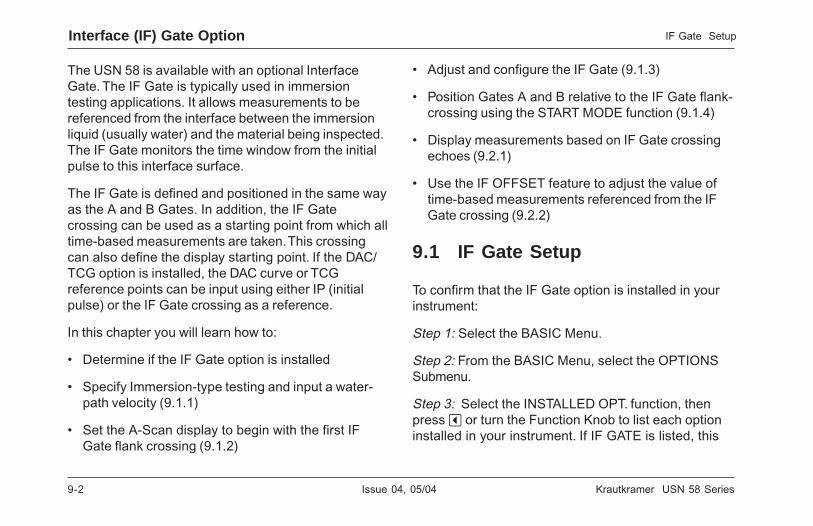
9-2 Issue 04, 05/04 Krautkramer USN 58 Series
9-2 Issue 04, 05/04 Krautkramer USN 58 Series
The USN 58 is available with an optional InterfaceGate. The IF Gate is typically used in immersiontesting applications. It allows measurements to bereferenced from the interface between the immersionliquid (usually water) and the material being inspected.The IF Gate monitors the time window from the initialpulse to this interface surface.
The IF Gate is defined and positioned in the same wayas the A and B Gates. In addition, the IF Gatecrossing can be used as a starting point from which alltime-based measurements are taken. This crossingcan also define the display starting point. If the DAC/TCG option is installed, the DAC curve or TCGreference points can be input using either IP (initialpulse) or the IF Gate crossing as a reference.
In this chapter you will learn how to:
• Determine if the IF Gate option is installed
• Specify Immersion-type testing and input a water-path velocity (9.1.1)
• Set the A-Scan display to begin with the first IFGate flank crossing (9.1.2)
• Adjust and configure the IF Gate (9.1.3)
• Position Gates A and B relative to the IF Gate flank-crossing using the START MODE function (9.1.4)
• Display measurements based on IF Gate crossingechoes (9.2.1)
• Use the IF OFFSET feature to adjust the value oftime-based measurements referenced from the IFGate crossing (9.2.2)
9.1 IF Gate Setup
To confirm that the IF Gate option is installed in yourinstrument:
Step 1: Select the BASIC Menu.
Step 2: From the BASIC Menu, select the OPTIONSSubmenu.
Step 3: Select the INSTALLED OPT. function, thenpress v or turn the Function Knob to list each optioninstalled in your instrument. If IF GATE is listed, this
Interface (IF) Gate Option IF Gate Setup

Krautkramer USN 58 Series Issue 04, 05/04 9-3
Krautkramer USN 58 Series Issue 04, 05/04 9-3
Interface (IF) Gate OptionIF Gate Setup
option is installed in your instrument. If not, contactAgfa NDT to install the option at our facility.
9.1.1 Immersion Testing Method
The IF Gate option allows you to specify two types ofmeasurement methods:
CONTACT-the probe is in physical contact with the testpiece IMMERSION-sound energy is transmitted fromthe probe, through the immersion fluid (usually water),and to the material being tested.
When the measurement method is set to IMMERSION,a WATER PATH VELOCITY can be input. Theinstrument’s default value is set to the acousticvelocity of water (0.0583 inch/microsecond). To selectthe IMMERSION measurement method and adjust thewater path velocity:
Step 1: Select the GATES Menu.
Step 2: Select the IF ADVanced Submenu.
Step 3: Select the DELAY MODE function, then pressv or turn the Function Knob to select IMMERSION.
With this function setting, measurement of theimmersion fluid thickness, the position of the IF Gate,and the IF Gate width are calculated using the fluidvelocity.
Step 4: With the IMMERSION measuring methodselected, the WATER PATH VELocity function isenabled. You may manually adjust the acoustic velocityfor the immersion fluid (usually water). The defaultvalue (0.0583 inch/microsecond) is set to the acousticvelocity of water.
H Note:
When DELAY MODE is set to IMMERSION, allcalculations that consider the elapsed time from theinitial pulse to the IF Gate crossings are based on theWATER PATH VELocity. When the IF Gate is used inother than immersion applications (such as with acontact probe) be sure to set the DELAY MODE toCONTACT. This ensures that the inputted acousticvelocity of the material being tested is used in cal-culations based on the IF Gate crossing.
Interface (IF) Gate OptionIF Gate Setup
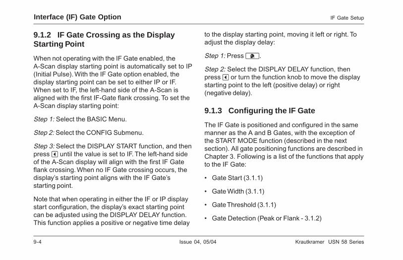
9-4 Issue 04, 05/04 Krautkramer USN 58 Series
9-4 Issue 04, 05/04 Krautkramer USN 58 Series
IF Gate SetupInterface (IF) Gate Option
9.1.2 IF Gate Crossing as the DisplayStarting Point
When not operating with the IF Gate enabled, theA-Scan display starting point is automatically set to IP(Initial Pulse). With the IF Gate option enabled, thedisplay starting point can be set to either IP or IF.When set to IF, the left-hand side of the A-Scan isaligned with the first IF-Gate flank crossing. To set theA-Scan display starting point:
Step 1: Select the BASIC Menu.
Step 2: Select the CONFIG Submenu.
Step 3: Select the DISPLAY START function, and thenpress v until the value is set to IF. The left-hand sideof the A-Scan display will align with the first IF Gateflank crossing. When no IF Gate crossing occurs, thedisplay’s starting point aligns with the IF Gate’sstarting point.
Note that when operating in either the IF or IP displaystart configuration, the display’s exact starting pointcan be adjusted using the DISPLAY DELAY function.This function applies a positive or negative time delay
to the display starting point, moving it left or right. Toadjust the display delay:
Step 1: Press h.
Step 2: Select the DISPLAY DELAY function, thenpress v or turn the function knob to move the displaystarting point to the left (positive delay) or right(negative delay).
9.1.3 Configuring the IF Gate
The IF Gate is positioned and configured in the samemanner as the A and B Gates, with the exception ofthe START MODE function (described in the nextsection). All gate positioning functions are described inChapter 3. Following is a list of the functions that applyto the IF Gate:
• Gate Start (3.1.1)
• Gate Width (3.1.1)
• Gate Threshold (3.1.1)
• Gate Detection (Peak or Flank - 3.1.2)
IF Gate SetupInterface (IF) Gate Option

Krautkramer USN 58 Series Issue 04, 05/04 9-5
Krautkramer USN 58 Series Issue 04, 05/04 9-5
Interface (IF) Gate OptionMeasurements Based on IF Gate Crossings
• Magnify Gate (3.1.3)
• Gate Alarm Logic (also allows the gate to be “TurnedOff” - 3.1.4)
9.1.4 Setting Gates A and B Relative to IFGate Using START MODE
When not operating with the IF Gate enabled, thestarting points for Gates A and B are positioned aspecified distance from the initial pulse (IP) or Gate Bis positioned a specified distance from the start ofGate A. With the IF Gate option enabled, the startingpoint for each gate can be measured from the firstflank crossing point in the IF Gate. Further, when theIF Gate option is enabled, and Gate B’s starting pointis positioned a specified distance from the first flankcrossing in Gate A, any change in Gate A’s first flankcrossing point will cause an equal change in thestarting point of Gate B. (see Figure 9-1)
To position a gate’s starting point a specified distancefrom another Gate’s first flank crossing (using STARTMODE function):
Step 1: Select the GATES Menu.
Step 2: Select the GATEMODE Submenu.
Step 3: Select the gate you wish to position using theGATE SELECT function.
Step 4: Select the START MODE function, and thenpress v to set the starting point reference to IP, IFGATE, or A GATE.
H Note:
When A Gate’s or B Gate’s START MODE function isset to IF GATE, any change in the IF-Gate’s first flankcrossing point will automatically produce an equalchange in the starting point of the linked gate. Thisfeature, known as Automatic Gate Tracking, existsbetween Gates A and B when B-Gate’s START MODEis set to A-GATE.
9.2 Measurements Based on IFGate Crossings
The IF Gate is typically used in immersion testingapplications. It allows measurements to be referencedfrom the interface between the immersion liquid
Interface (IF) Gate OptionMeasurements Based on IF Gate Crossings

9-6 Issue 04, 05/04 Krautkramer USN 58 Series
9-6 Issue 04, 05/04 Krautkramer USN 58 Series
Measurements Based on IF Gate CrossingsInterface (IF) Gate Option
FIGURE 9-1—The START MODE function allows you to link the starting point of Gates A and B to the IF Gate’s firstflank crossing point. The flank crossing is always used as a reference, whether the IF Gate’s detection setting is set toflank or peak. It also allows you to link the starting point of Gate B to Gate A.
FIGURE 9-1—The START MODE function allows you to link the starting point of Gates A and B to the IF Gate’s firstflank crossing point. The flank crossing is always used as a reference, whether the IF Gate’s detection setting is set toflank or peak. It also allows you to link the starting point of Gate B to Gate A.
Measurements Based on IF Gate CrossingsInterface (IF) Gate Option

Krautkramer USN 58 Series Issue 04, 05/04 9-7
Krautkramer USN 58 Series Issue 04, 05/04 9-7
(usually water) and the material being inspected. Inimmersion applications, the IF Gate is usuallypositioned so that the first echo that returns from theimmersion fluid-to-test material interface triggers it. Thestarting positions of Gates A and B are then usuallytied to the IF Gate’s first flank crossing point (using theSTART MODE function located in the GATEMODESubmenu).
9.2.1 IF-Gate Measurements
When the IF Gate is enabled, the measured valuesshown in Figure 9-2 can be displayed (see section 3.5to select measured readings for display using theRESULTS Menu). It’s important to note that therelative distance measurements (such as SBI, thethickness between the IF Gate trigger and the B Gatetrigger) can only be displayed if the later gate’s STARTMODE (located in the GATEMODE Submenu) is set toIF GATE.
H Note:
Gate-to-gate multi-echo measurements (such as SAI)are only available for display when the trailing gate’s(in this case, A-Gate) START MODE is set to theleading gate (in this case, IF Gate). See 9.1.4 to setSTART MODE. This also applies to the other multi-echo measurements, SBI and SBA.
9.2.2 Using IF OFFSET
When the IF Gate option is enabled, time basedmeasurements taken from the IF Gate detection point(flank or peak crossing depending on the IF GateDETECTION MODE setting) can be adjusted using theIF OFFSET function. Setting IF OFFSET equal to anyvalue other than zero modifies the calculated Time-of-Flight (TOF) to the IF Gate detection point. TheOFFSET function also modifies all time basedmeasurements that are referenced to this IF Gatedetection point. To adjust the IF OFFSET:
Step 1: Select the GATES Menu.
Step 2: Select the IF ADVanced Submenu.
Interface (IF) Gate OptionMeasurements Based on IF Gate Crossings

9-8 Issue 04, 05/04 Krautkramer USN 58 Series
9-8 Issue 04, 05/04 Krautkramer USN 58 Series
Step 3: Select the IF OFFSET function, then press vor turn the Function Knob to adjust the level of offset.This will modify all time based measurements thatdepend on an IF Gate crossing.
H Note:
The IF OFFSET function directly changes the TOFcalculated for the IF Gate detection point. This has theeffect of adjusting measured values whenever timebased measurements depend on an IF Gate crossing.Do not set the offset value to any number other thanzero unless you are familiar with the effects of thisoffset on the measured data.
Measurements Based on IF Gate CrossingsInterface (IF) Gate Option

Krautkramer USN 58 Series Issue 04, 05/04 9-9
Krautkramer USN 58 Series Issue 04, 05/04 9-9
Interface (IF) Gate OptionMeasurements Based on IF Gate Crossings
FIGURE 9-2—These readings can be displayed only when the IF Gate option is enabled.
FIGURE 9-2—These readings can be displayed only when the IF Gate option is enabled.
Interface (IF) Gate OptionMeasurements Based on IF Gate Crossings

9-10 Issue 04, 05/04 Krautkramer USN 58 Series
9-10 Issue 04, 05/04 Krautkramer USN 58 Series
THIS PAGE WAS INTENTIONALLY LEFT BLANK.
THIS PAGE WAS INTENTIONALLY LEFT BLANK.

Krautkramer USN 58 Series Issue 04, 05/04 10-1
Krautkramer USN 58 Series Issue 04, 05/04 10-1
DGS Option 10
DGS Option 10

10-2 Issue 04, 05/04 Krautkramer USN 58 Series
10-2 Issue 04, 05/04 Krautkramer USN 58 Series
DGS Option Using DGS
DGS Option Using DGS
The USN 58 is available with an optional Distance GainSizing (DGS) feature. This feature is accessed throughthe DGS menu, which is located by pressing u belowthe NEXT selection on the HOME menu bar. The DGSfeature allows the user to use a particular probe tocompare a reflector in a test piece with a knownstandard reflector.
The DGS feature relies on a reference curve based ona recorded reference point. The procedure for recordinga reference point using the DGS Menu is describedbelow.
10.1 Using DGS
When the DGS function is in use, echoes from equallysized reflectors located at varying depths appear to liealong the DGS Reference Curve. When operating inDGS mode, the DGS Reference Curve appears on thedisplay screen. Before using the DGS function, do thefollowing:
• Calibrate the instrument/probe combination
• Make all required instrument settings related to thepulser, receiver, and material-velocity settings.
Calibrating or changing certain settings after the DGSReference Echo has been recorded will cause thestored reference to be deleted.
10.1.1 Specifying a Probe and Preparing toRecord the Reference Echo
Before using the DGS feature to evaluate reflectors intest pieces, the characteristics of the attached probemust be specified, certain characteristics of thereference standard must be input, and a referenceecho must be stored. To specify the probecharacteristics:
Step 1: Press u below the NEXT selection on theHOME menu bar, then press the correct u key toaccess the DGS menu.
Step 2: Select the SETUP submenu, then the PROBE# function. Once activated, this function allows you tochoose from the list of probe types in Table 10-1.These are probes for which probe characteristics arealready input in the USN 58, with the exception of theuser-defined probe (PROBE # 1):

Krautkramer USN 58 Series Issue 04, 05/04 10-3
Krautkramer USN 58 Series Issue 04, 05/04 10-3
DGS OptionUsing DGS
DGS OptionUsing DGS
Table 10-1
DGS PROBE-NUMBER ASSIGNMENTS
InstrumentSetting
ProbeType
InstrumentSetting
ProbeType
PROBE #1 User defined PROBE #14 SWB45-2
PROBE #2 B1S PROBE #15 SWB60-2
PROBE #3 B2S PROBE #16 SWB70-2
PROBE #4 B4S PROBE #17 SWB45-5
PROBE #5 MB2S PROBE #18 SWB60-5
PROBE #6 MB4S PROBE #19 SWB70-5
PROBE #7 MB5S PROBE #20 WB45-1
PROBE #8 MWB45-2 PROBE #21 WB60-1
PROBE #9 MWB60-2 PROBE #22 WB70-1
PROBE #10 MWB70-2 PROBE #23 WB45-2
PROBE #11 MWB45-4 PROBE #24 WB60-2
PROBE #12 MWB60-4 PROBE #25 WB70-2
PROBE #13 MWB70-4
Step 3: If the user-defined probe type (PROBE #1) isselected, you can then select the PROBE NAMEfunction. Then use the Gain and Function knobs (theGain knob changes location within the name, theFunction knob changes the character value) to input anew name. Note that selecting any PROBE # valueother than 1 will prevent you from modifying thePROBE NAME or any of the other settings describedin Step 4.
Step 4: If the user-defined probe type (PROBE #1) isselected, you must then select the DGS PROBEsubmenu and input the characteristics for the probeyou’ve connected including:
XTAL FREQUENCY—The probe’s frequency rating
EFF. DIAMETER—The probe element’s effectivediameter rating
DELAY VELOCITY—User determined delay-linevelocity
Note that these characteristics can’t be changed forany probes other than PROBE #1.

10-4 Issue 04, 05/04 Krautkramer USN 58 Series
10-4 Issue 04, 05/04 Krautkramer USN 58 Series
10.1.2 Record the Reference Echo thatDefines the DGS Curve
Prior to generating the DGS curve, a test standard witha known reflector must be used to define a referencepoint. Acceptable test standards include these refer-ence types:
• BW—Backwall echo with reference defect sizedefined as infinity
• SDH—Side Drilled Hole with a reference defect sizedefined as the hole’s diameter
• FBH—Flat Bottom Hole with a reference defect sizeequal to the hole’s facial diameter
Follow these steps and Figure 10-1 to record a refer-ence echo:
Step 1: Select the REF ECHO submenu, then theREFERENCE TYPE function. Once activated, thisfunction allows you to select one of the three referencetypes described above, and specify the size of theknown standard’s reference flaw.
Step 2: Couple the probe to the known standard,capture the reference flaw so that it’s reflected echo isdisplayed on the instrument’s A-Scan, and adjust theA-Gate’s starting point to ensure that the resultingecho triggers the gate.
Step 3: Adjust the gain knob until the reference flaw’sA-Scan peak measures 80% of FSH (A%A = 80%).
Step 4: With the probe coupled to the standard, andthe reference flaw’s echo captured by the A-Gate,press v next to the RECORD REF function to store aDGS reference echo.
H Note:
When a DGS reference echo is stored, the willappear in the display’s status bar (upper right corner).Note that only one DGS reference echo can be storedat a time. To delete the currently stored reference,access the REF CORR submenu, select DELETEREF, and follow the on-screen prompts.
H Note:
When a DGS reference echo is stored, twomeasurement results boxes will be automatically set (ifnot already configured) to display SA and A%A values.
DGS Option Using DGS
DGS Option Using DGS
10.1.2 Record the Reference Echo thatDefines the DGS Curve
Prior to generating the DGS curve, a test standard witha known reflector must be used to define a referencepoint. Acceptable test standards include these refer-ence types:
• BW—Backwall echo with reference defect sizedefined as infinity
• SDH—Side Drilled Hole with a reference defect sizedefined as the hole’s diameter
• FBH—Flat Bottom Hole with a reference defect sizeequal to the hole’s facial diameter
Follow these steps and Figure 10-1 to record a refer-ence echo:
Step 1: Select the REF ECHO submenu, then theREFERENCE TYPE function. Once activated, thisfunction allows you to select one of the three referencetypes described above, and specify the size of theknown standard’s reference flaw.
Step 2: Couple the probe to the known standard,capture the reference flaw so that it’s reflected echo isdisplayed on the instrument’s A-Scan, and adjust theA-Gate’s starting point to ensure that the resultingecho triggers the gate.
Step 3: Adjust the gain knob until the reference flaw’sA-Scan peak measures 80% of FSH (A%A = 80%).
Step 4: With the probe coupled to the standard, andthe reference flaw’s echo captured by the A-Gate,press v next to the RECORD REF function to store aDGS reference echo.
H Note:
When a DGS reference echo is stored, the willappear in the display’s status bar (upper right corner).Note that only one DGS reference echo can be storedat a time. To delete the currently stored reference,access the REF CORR submenu, select DELETEREF, and follow the on-screen prompts.
H Note:
When a DGS reference echo is stored, twomeasurement results boxes will be automatically set (ifnot already configured) to display SA and A%A values.

Krautkramer USN 58 Series Issue 04, 05/04 10-5
Krautkramer USN 58 Series Issue 04, 05/04 10-5
DGS OptionUsing DGS
DGS OptionUsing DGS
FIGURE 10-1—Recording a DGS reference point from which a DGS Curve will be generated.
FIGURE 10-1—Recording a DGS reference point from which a DGS Curve will be generated.

10-6 Issue 04, 05/04 Krautkramer USN 58 Series
10-6 Issue 04, 05/04 Krautkramer USN 58 Series
These result selections will remain locked until theDGS reference is deleted.
The following two adjustments should be made prior torecording a reference echo. Changing these valuesafter the DGS curve is generated will cause the curveto be deleted.
REF ATTEN (found in the REF CORR submenu)—Specify a sound attenuation value (in dB per inch ormm of material thickness) for the material from whichthe known standard is made.
AMPL CORRECT (found in the REF CORRsubmenu)—Correction required when using an angle-beam type probe. This value is specified on the probe’sdata sheet.
10.1.3 Display and Adjust the DGS Curve
Once a reference echo has been recorded, the DGScurve is displayed simply by selecting the SETUPsubmenu in the DGS menu, then setting the DGSMODE function to ON (Figure 10-2). Note thatswitching this value to OFF does not delete the
curve — it simply removes the curve from the displayand disables the DGS mode. Once the DGS Curve isdisplayed, it can be adjusted using one of these threefunctions:
TEST ATTEN (found in the MAT ATTN submenu)—Specify a sound attenuation value (in dB per inch ormm of material thickness) for the material from whichthe test piece is made.
TRANSFER CORR. (found in the MAT ATTN submenu)—dB compensation for difference in coupling condi-tions between the known standard and the test piece.
DGS CURVE (found in the SETUP and EVALUATEsubmenus)—Positions the probe’s DGS Curve basedon the size of the reflector (flaw) being tested. Thesetting will usually depend on the largest acceptableflaw size.
DGS Option Using DGS
DGS Option Using DGS
These result selections will remain locked until theDGS reference is deleted.
The following two adjustments should be made prior torecording a reference echo. Changing these valuesafter the DGS curve is generated will cause the curveto be deleted.
REF ATTEN (found in the REF CORR submenu)—Specify a sound attenuation value (in dB per inch ormm of material thickness) for the material from whichthe known standard is made.
AMPL CORRECT (found in the REF CORRsubmenu)—Correction required when using an angle-beam type probe. This value is specified on the probe’sdata sheet.
10.1.3 Display and Adjust the DGS Curve
Once a reference echo has been recorded, the DGScurve is displayed simply by selecting the SETUPsubmenu in the DGS menu, then setting the DGSMODE function to ON (Figure 10-2). Note thatswitching this value to OFF does not delete the
curve — it simply removes the curve from the displayand disables the DGS mode. Once the DGS Curve isdisplayed, it can be adjusted using one of these threefunctions:
TEST ATTEN (found in the MAT ATTN submenu)—Specify a sound attenuation value (in dB per inch ormm of material thickness) for the material from whichthe test piece is made.
TRANSFER CORR. (found in the MAT ATTN submenu)—dB compensation for difference in coupling condi-tions between the known standard and the test piece.
DGS CURVE (found in the SETUP and EVALUATEsubmenus)—Positions the probe’s DGS Curve basedon the size of the reflector (flaw) being tested. Thesetting will usually depend on the largest acceptableflaw size.

Krautkramer USN 58 Series Issue 04, 05/04 10-7
Krautkramer USN 58 Series Issue 04, 05/04 10-7
DGS OptionUsing DGS
DGS OptionUsing DGS
FIGURE 10-2—DGS Curve
FIGURE 10-2—DGS Curve
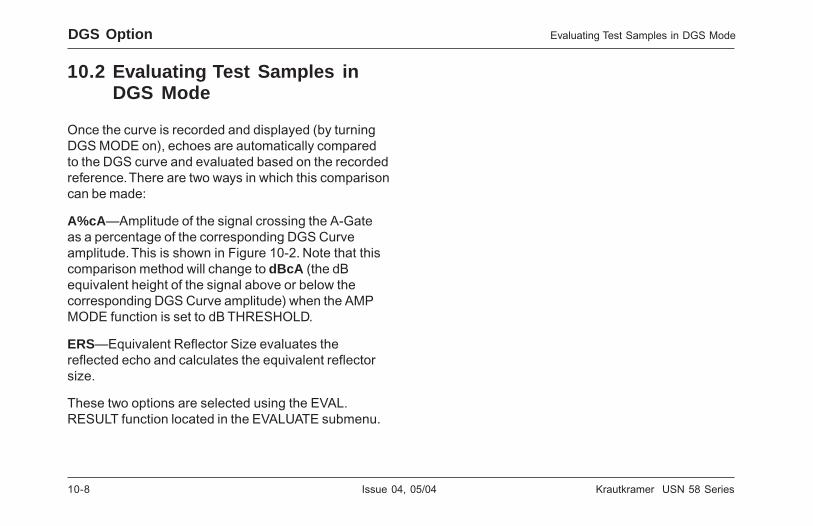
10-8 Issue 04, 05/04 Krautkramer USN 58 Series
10-8 Issue 04, 05/04 Krautkramer USN 58 Series
DGS Option Evaluating Test Samples in DGS Mode
DGS Option Evaluating Test Samples in DGS Mode
10.2 Evaluating Test Samples inDGS Mode
Once the curve is recorded and displayed (by turningDGS MODE on), echoes are automatically comparedto the DGS curve and evaluated based on the recordedreference. There are two ways in which this comparisoncan be made:
A%cA—Amplitude of the signal crossing the A-Gate asa percentage of the corresponding DGS Curve ampli-tude. This is shown in Figure 10-2. Note that thiscomparison method will change to dBcA (the dBequivalent height of the signal above or below thecorresponding DGS Curve amplitude) when the AMPMODE function is set to dB THRESHOLD.
ERS—Equivalent Reflector Size evaluates thereflected echo and calculates the equivalent reflectorsize.
These two options are selected using the EVAL.RESULT function located in the EVALUATE submenu.
10.2 Evaluating Test Samples inDGS Mode
Once the curve is recorded and displayed (by turningDGS MODE on), echoes are automatically comparedto the DGS curve and evaluated based on the recordedreference. There are two ways in which this comparisoncan be made:
A%cA—Amplitude of the signal crossing the A-Gateas a percentage of the corresponding DGS Curveamplitude. This is shown in Figure 10-2. Note that thiscomparison method will change to dBcA (the dBequivalent height of the signal above or below thecorresponding DGS Curve amplitude) when the AMPMODE function is set to dB THRESHOLD.
ERS—Equivalent Reflector Size evaluates thereflected echo and calculates the equivalent reflectorsize.
These two options are selected using the EVAL.RESULT function located in the EVALUATE submenu.

Krautkramer USN 58 Series Issue 04, 05/04 11-1
Krautkramer USN 58 Series Issue 04, 05/04 11-1
BEA (Backwall Echo Attenuator) Option 11
BEA (Backwall Echo Attenuator) Option 11

11-2 Issue 04, 05/04 Krautkramer USN 58 Series
11-2 Issue 04, 05/04 Krautkramer USN 58 Series
BEA (Backwall Echo Attenuator) Option
The USN 58 is available with an optional BackwallEcho Attenuator (BEA) feature. This feature isaccessed through the PLSRVR menu by pressing ubelow the BCK ATTN submenu. The BEA featureallows the user to position the B-Gate to correspondwith a specific test-material depth (typically to matchthe test part’s backwall), and then adjust the gainsetting for only those echoes falling within the B-Gate’sregion.
When BEA is activated, the gain applied to thebackwall echo is set lower than the system gainapplied to all other echoes. This allows backwallechoes that peak higher than full-screen height to bebrought into view on-screen and monitored. All gate-related functions, including gate-logic control, time-base measurements, amplitude measurements, andTTL alarm assignments operate as they do when not inBEA mode. See section 11.2 for additional notes onBEA operation.
BEA (Backwall Echo Attenuator) Option
11.1 Using Backwall EchoAttenuator Mode
H Note:
B-Gate must be activated to use BEA.
When the BEA function is in use, a different gain levelis applied to backwall and other echoes that fall withinthe region of the B-Gate. To operate in BEA mode dothe following:
Step 1: Activate Gate B.
Step 2: Press u below the PLSRVR menu on theHome Menu Bar.
Step 3: Press u below the BCK ATTN submenu. Thefunction bar will appear as shown in Figure 11-1.
Step 4: Press v next to the MODE function until theBEA Mode is turned ON. The BEA icon will appear. Thevalue of BW GAIN is now the level of gain applied toall A-Scan echoes falling within B-Gate’s region.
Step 5: Press v next to the B-START or GATE BWIDTH functions to adjust the position and width ofGate B.
The USN 58 is available with an optional BackwallEcho Attenuator (BEA) feature. This feature isaccessed through the PLSRVR menu by pressing ubelow the BCK ATTN submenu. The BEA featureallows the user to position the B-Gate to correspondwith a specific test-material depth (typically to matchthe test part’s backwall), and then adjust the gainsetting for only those echoes falling within the B-Gate’sregion.
When BEA is activated, the gain applied to thebackwall echo is set lower than the system gainapplied to all other echoes. This allows backwallechoes that peak higher than full-screen height to bebrought into view on-screen and monitored. All gate-related functions, including gate-logic control, time-base measurements, amplitude measurements, andTTL alarm assignments operate as they do when not inBEA mode. See section 11.2 for additional notes onBEA operation.
11.1 Using Backwall EchoAttenuator Mode
H Note:
B-Gate must be activated to use BEA.
When the BEA function is in use, a different gain levelis applied to backwall and other echoes that fall withinthe region of the B-Gate. To operate in BEA mode dothe following:
Step 1: Activate Gate B.
Step 2: Press u below the PLSRVR menu on theHome Menu Bar.
Step 3: Press u below the BCK ATTN submenu. Thefunction bar will appear as shown in Figure 11-1.
Step 4: Press v next to the MODE function until theBEA Mode is turned ON. The BEA icon will appear. Thevalue of BW GAIN is now the level of gain applied toall A-Scan echoes falling within B-Gate’s region.
Step 5: Press v next to the B-START or GATE BWIDTH functions to adjust the position and width ofGate B.
Using Backwall Echo Attenuator Mode
Using Backwall Echo Attenuator Mode

Krautkramer USN 58 Series Issue 04, 05/04 11-3
Krautkramer USN 58 Series Issue 04, 05/04 11-3
Step 6: Press v next to the BW GAIN function, thenadjust the amount of gain to be applied to all signalswithin B-Gate’s region.
11.2 Notes on Operating in BEAMode
The following notes identify other instrument featuresthat are affected when operating in BEA mode.
• The B-Gate Start Mode (Gates – Gate Mode – StartMode) cannot be set to A-Gate (but can be set to IPor IF-Gate)
• When A-Gate and B-Gate overlap, the gain settingfor BEA/B-Gate supersedes the general instrument-gain setting and is applied to all echoes under B-Gate’s region.
• Time-base and amplitude measurements involvingGate B are made based on the attenuated echo’sposition in Gate B and the user-defined trigger point(Flank or Peak).
• All gate logic and TTL alarm assignment functionsoperate as they do when not in BEA mode
FIGURE 11-1—Turning on the BEA function allows thegain level applied to all echoes in Gate B (the right-handgate in this figure) to be adjusted independent of thelevel of gain applied to all other echoes. In this case 28dB is applied to all echoes within the region of Gate B,while 52 dB is applied to all other echoes.
BEA (Backwall Echo Attenuator) Option
BEA (Backwall Echo Attenuator) Option
Notes on Operating in BEA Mode
Notes on Operating in BEA Mode

11-4 Issue 04, 05/04 Krautkramer USN 58 Series
11-4 Issue 04, 05/04 Krautkramer USN 58 Series
THIS PAGE WAS INTENTIONALLY LEFT BLANK.
THIS PAGE WAS INTENTIONALLY LEFT BLANK.

Krautkramer USN 58 Series Issue 04, 05/04 12-1
Krautkramer USN 58 Series Issue 04, 05/04 12-1
VGA Connector Option 12
VGA Connector Option 12

12-2 Issue 04, 05/04 Krautkramer USN 58 Series
12-2 Issue 04, 05/04 Krautkramer USN 58 Series
VGA Connector Option
The instrument can be equipped with an additionalDB15 style connector to which a monitor or PCprojector can connect. The VGA output is providedthrough this direct plug-in connector, which is locatedon the instrument‘s back panel, beneath the hand grip.
The instrument can be equipped with an additionalDB15 style connector to which a monitor or PCprojector can connect. The VGA output is providedthrough this direct plug-in connector, which is locatedon the instrument‘s back panel, beneath the hand grip.
VGA Connector Option

Krautkramer USN 58 Series Issue 04, 05/04 13-1
Krautkramer USN 58 Series Issue 04, 05/04 13-1
Appendix 13
Appendix 13

13-2 Issue 04, 05/04 Krautkramer USN 58 Series
13-2 Issue 04, 05/04 Krautkramer USN 58 Series
Appendix Charging the Standard Lithium Battery Pack
13.1 Charging the StandardLithium Battery Pack
USN 58 Series instruments are supplied with astandard Lithium battery pack. This pack is speciallydesigned for the USN 58 and approximately doublesthe operating time when compared to optional NiMHD-cells.
Only the standard Lithium battery pack can becharged in the instrument by connecting theKrautkramer Lithium battery charger to the Lithiumbattery charging port identified in Figure 1-1 (4-pinconnector on the side of the Lithium battery pack).
H Note:
A spare Lithium battery pack can be recharged bysimply connecting it to the Lithium Battery PackCharger.
The Lithium battery pack‘s charging cycle takesapproximately seven hours to complete. Theinstrument can be used while the Lithium charger isconnected and the battery pack is being charged butthe charging time will be somewhat longer.
The Lithium battery pack’s charger contains severalindicating LED’s:
• Green POWER LED illuminates anytime the chargeris connected to either the battery pack or an ACpower source.
• Green CHARGE LED illuminates to indicate that theLithium battery pack is being charged.
• Yellow DONE LED illuminates to indicate that thebattery charging cycle is complete.
H Note:
When both the Green CHARGE LED and the YellowDONE LED are on at the same time a ‘trickle’ charge isgoing into the batteries to ‘top’ them off.
• Red ERROR LED has two functions. It can indicatethat the pack voltage has fallen too low to berecharged. In this case the pack is either worn out orcontains a faulty cell. The pack must be replaced.The LED can also indicate that an over/undertemperature condition exists in the pack. Thetemperature of the pack must remain within a rangeof 0 to 60 degree C in order for the charger to

Krautkramer USN 58 Series Issue 04, 05/04 13-3
Krautkramer USN 58 Series Issue 04, 05/04 13-3
operate. If the temperature of the pack falls outsideof these limits, the RED LED will illuminate andcharging will stop. When the pack temperaturereturns to a safe operating level, charging willresume.
13.2 Charging the Optional D-CellBatteries
Step 1: To charge the six optional rechargeablebatteries (9.0 Ahr NiMH), you must first remove theoptional battery tray. To remove the tray simply placethe instrument screen-side down and loosen the fourknurl-headed screws on the rear of the instrument.When all four screws are loosened (they will notseparate completely from the tray), lift the battery trayoff of the back of the instrument.
Step 2: A separate battery charger is required tocharge the 9.0 Ahr NiMH batteries when removed fromthe instrument. Plug the charger’s power cord into a100-240 VAC power source. It’s GREEN indicationlamp will illuminate when the charger is supplied withpower.
AppendixCharging the Optional D-Cell Batteries
AppendixCharging the Optional D-Cell Batteries
Step 3: The charger adapter and battery pack aredesigned to work together. Only use the charger tocharge batteries that are installed in the pack. Mate thebattery pack to the charger adapter as shown above.Note that the charging terminals from the pack andcharger adapter must be properly aligned for chargingto proceed.
Step 4: When charging the battery pack, the charger’sYELLOW indication lamp will light steadily.
Step 5: When charging is complete (typically after sixto seven hours) the YELLOW indication lamp will blink.You may remove the battery pack from the charger andre-install the pack to the back of the instrument.
H Note:
The optional external charger may only be used tocharge 9.0 Ahr NiMH batteries.

13-4 Issue 04, 05/04 Krautkramer USN 58 Series
13-4 Issue 04, 05/04 Krautkramer USN 58 Series
THIS PAGE WAS INTENTIONALLY LEFT BLANK.
THIS PAGE WAS INTENTIONALLY LEFT BLANK.

Krautkramer USN 58 Series Issue 04, 05/04 14-1
Krautkramer USN 58 Series Issue 04, 05/04 14-1
Index 14
Index 14

14-2 Issue 04, 05/04 Krautkramer USN 58 Series
14-2 Issue 04, 05/04 Krautkramer USN 58 Series
Index
Index
Symbols
% Screen Height ....................................................3-11
A
A%A ......................................................................3-16
A%B ......................................................................3-16
A%cA ....................................................................10-6
A-SCAN ENHANCE ................................................ 6-4
A-Scan Range ........................................................2-11
A-Scan REJECT Level ...........................................2-19
ALARMS ................................................................. 3-9
ALRM RST ............................................................4-13
AMPL CORRECT...................................................10-6
AMPLITUDE ..........................................................3-11
Amplitude Measurement ........................................3-11
analog outputs ........................................................ 7-3
angle beam probe...................................................3-15
ASCAN COLOR ...................................................... 2-8
ASCAN MODE........................................................ 2-8
Attaching Notes .....................................................4-10
Attachment, Probe .................................................2-11
ATTENUATION ........................................................ 6-7
Audible Alarm ......................................................... 3-9
AUTOCAL ..............................................................2-20
AWS D1.1 ............................................................... 6-7
B
Backwall Echo Attenuator ............................. 1-24, 11-2
BASELINE BREAK ................................................. 6-4
BATTERY TYPE ..................................................... 2-2
Baud Rate ..............................................................5-20
BCK ATTN .............................................................11-2
BEA .......................................................................11-2
Beam Index Point (BIP) .........................................3-15
Behind the Freeze Mode ........................................ 4-15

Krautkramer USN 58 Series Issue 04, 05/04 14-3
Krautkramer USN 58 Series Issue 04, 05/04 14-3
Index
Index
BRIGHTNESS ........................................................ 2-6
BW.........................................................................10-4
C
COLOR ................................................................... 2-7
COLORING ............................................................3-16
COLOR LEG ..........................................................3-16
COMPARE .............................................................3-14
CONFIG Submenu .................................................1-12
CONTACT ............................................................... 9-3
COPY MODE .........................................................5-18
COUNT ................................................................... 6-3
CREATE NEW ........................................................ 5-6
CUSTOM LINEAR ................................................... 5-8
D
D1.1 RATING .......................................................... 6-7
DA..........................................................................3-17
DAC ........................................................................ 8-2
DAC curves ............................................................. 8-6
DAC Offset Curves ................................................. 8-9
DAMPING. .............................................................2-11
Data Out Inhibit ....................................................... 7-3
data-set file ............................................................. 5-6
Date ........................................................................ 2-4
Date Valid ................................................................ 7-3
DB .........................................................................3-17
dB Reference .......................................................... 4-6
dB STEP ................................................................ 4-4
dB Threshold ..........................................................3-11
dBcA......................................................................10-6
dBrA ......................................................................3-16
dBrB ......................................................................3-16
dBtA ......................................................................3-16
dBtB ......................................................................3-16

14-4 Issue 04, 05/04 Krautkramer USN 58 Series
14-4 Issue 04, 05/04 Krautkramer USN 58 Series
Index
Index
DELAY MODE ........................................................ 9-3
DELAY VELOCITY .................................................10-3
Deleting (CLEARING) Existing Data Files ..............5-11
DGS .......................................................................10-2
DGS Reference Curve ............................................10-2
Display Delay .........................................................2-14
Display Grid ............................................................ 2-6
Display Screen Features ........................................1-16
DISPLAY START ...................................................2-15
DISPLAY-COLOR .................................................... 2-7
Distance Amplitude Correction ................................ 8-2
Distance Gain Size ................................................1-23
DUAL. ..................................................................... 2-9
E
EFF. DIAMETER ....................................................10-3
Equivalent Reflector Size .......................................10-8
ERS .......................................................................10-8
EVAL. RESULT ......................................................10-8
External Descriptions .............................................. 7-3
F
FBH .......................................................................10-4
Features of the USN 58 .........................................1-19
FILENAME ............................................................. 5-6
FILENAME Submenu .............................................1-14
FREEZE MODE ........................................... 3-12, 4-15
G
gain ......................................................................... 4-4
GAIN Submenu ......................................................1-13
Gate Detection Method ........................................... 3-6
GATE START .......................................................... 3-4
GATE THRESHOLD ................................................ 3-6
GATE WIDTH .......................................................... 3-6

Krautkramer USN 58 Series Issue 04, 05/04 14-5
Krautkramer USN 58 Series Issue 04, 05/04 14-5
Index
Index
GATEMODE Submenu ...........................................1-13
GATES menu .......................................................... 3-2
GATES-ALARMS-LOGIC ........................................ 3-9
GRID. ...................................................................... 2-6
H
HELP SCREENS ...................................................4-17
HORN ..................................................................... 3-9
I
icons ......................................................................1-19
IF ADV .................................................................... 9-3
IF Gate ................................................................... 9-2
IF OFFSET ............................................................. 9-7
Immersion Testing ................................................... 9-3
INDICATION............................................................ 6-7
INSTANTANIOUS ...................................................3-11
L
LA ..........................................................................3-19
Language ................................................................ 2-4
LATCHED...............................................................3-11
LB ..........................................................................3-19
LINEAR................................................................... 5-8
LOCK .....................................................................3-21
LOG TO FILE .........................................................5-19
LOG TO PORT .......................................................5-19
Logger Files ............................................................ 5-6
LOGIC .................................................................... 3-9
LOS .......................................................................5-20
Loss of Signal ........................................................5-20
LRG DISP ..............................................................4-13
M
MAGNIFY ..............................................................4-10

14-6 Issue 04, 05/04 Krautkramer USN 58 Series
14-6 Issue 04, 05/04 Krautkramer USN 58 Series
Index
Index
MAGNIFY GATE ....................................................4-13
MASTER LOCK .....................................................3-20
MAT ATTN..............................................................10-6
material-thickness limits ........................................3-11
memo ....................................................................5-12
MULTISTORE ......................................................... 5-8
MUXD Ascan Enable .............................................. 7-5
N
navigate through the file contents ..........................4-10
NEG HALFWAVE ...................................................2-17
NOISE IMMN .......................................................... 6-2
Noise Immunization ................................................ 6-2
Notes for Attachment to ThicknessMeasurements ................................................5-14
O
O-DIAMETER ........................................................3-16
OFFSET ................................................................. 8-9
Optional Features ...................................................1-23
OPTIONS Submenu...............................................1-12
Output Delay ........................................................... 7-3
Outputting to a Computer .......................................5-20
P
PA ..........................................................................3-17
PARADUMP ...........................................................5-19
PB .........................................................................3-17
PEAK STD ............................................................3-14
POS HALFWAVE ...................................................2-17
POSITION .............................................................. 3-4
Positioning Gates .................................................... 3-4
Pre-calibration Check List ......................................2-18
Previewing Existing Data Files ...............................5-11
PRF .......................................................................2-15
PRF VALUE ...........................................................2-15
MAGNIFY GATE ....................................................4-13
MASTER LOCK .....................................................3-20
MAT ATTN..............................................................10-6
material-thickness limits ........................................3-11
memo ....................................................................5-12
MULTISTORE ......................................................... 5-8
MUXD Ascan Enable .............................................. 7-5
N
navigate through the file contents ..........................4-10
NEG HALFWAVE ...................................................2-17
NOISE IMMN .......................................................... 6-2
Noise Immunization ................................................ 6-2
Notes for Attachment to ThicknessMeasurements ................................................5-14
O
O-DIAMETER ........................................................3-16
OFFSET ................................................................. 8-9
Optional Features...................................................1-23
OPTIONS Submenu...............................................1-12
Output Delay ........................................................... 7-3
Outputting to a Computer .......................................5-20
P
PA ..........................................................................3-17
PARADUMP ...........................................................5-19
PB .........................................................................3-17
PEAK STD ............................................................3-14
POS HALFWAVE ...................................................2-17
POSITION .............................................................. 3-4
Positioning Gates .................................................... 3-4
Pre-calibration Check List ......................................2-18
Previewing Existing Data Files ...............................5-11
PRF .......................................................................2-15
PRF VALUE ...........................................................2-15
Krautkramer USN 58 Series Issue 04, 05/04 14-7
Krautkramer USN 58 Series Issue 04, 05/04 14-7
Index
Index
PRINTER ...............................................................5-16
Printing a Report .................................................... 5-16
PROBE # ...............................................................10-2
PROBE ANGLE .....................................................3-15
Probe Attachment ..................................................2-11
PROBE DELAY .....................................................2-22
PROBE NAME.......................................................10-3
Probe Type .............................................................. 2-9
Pulser VOLTAGE Level...........................................2-18
Pulser Repetition Frequency ..................................2-15
PULSER Submenu ................................................1-12
Pulser Type ............................................................2-17
Pulser Width ...........................................................2-18
PULSER-DAMPING ...............................................2-11
R
RA .........................................................................3-17
RANGE ..................................................................2-14
RANGE Submenu ..................................................1-12
RB .........................................................................3-17
RECEIVER Submenu ............................................1-13
RECEIVER-FREQUENCY ...................................... 2-9
RECORD ................................................................ 8-3
RECTIFY ...............................................................2-17
REF ATTEN ...........................................................10-6
REF CORR ............................................................10-6
REF ECHO ............................................................10-4
REFERENCE .......................................................... 6-7
Reference Echo .....................................................10-2
REFERENCE TYPE...............................................10-4
REJECT ................................................................2-19
remote control ......................................................... 7-6
REPORT ................................................................5-18
Report Headers ......................................................5-12
Reports ..................................................................5-16
PRINTER ...............................................................5-16
Printing a Report ....................................................5-16
PROBE # ...............................................................10-2
PROBE ANGLE .....................................................3-15
Probe Attachment ..................................................2-11
PROBE DELAY .....................................................2-22
PROBE NAME.......................................................10-3
Probe Type .............................................................. 2-9
Pulser VOLTAGE Level ...........................................2-18
Pulser Repetition Frequency ..................................2-15
PULSER Submenu ................................................1-12
Pulser Type ............................................................2-17
Pulser Width ...........................................................2-18
PULSER-DAMPING ...............................................2-11
R
RA .........................................................................3-17
RANGE ..................................................................2-14
RANGE Submenu ..................................................1-12
RB .........................................................................3-17
RECEIVER Submenu ............................................1-13
RECEIVER-FREQUENCY ...................................... 2-9
RECORD ................................................................ 8-3
RECTIFY ...............................................................2-17
REF ATTEN ...........................................................10-6
REF CORR ............................................................10-6
REF ECHO ............................................................10-4
REFERENCE .......................................................... 6-7
Reference Echo .....................................................10-2
REFERENCE TYPE...............................................10-4
REJECT ................................................................2-19
remote control ......................................................... 7-6
REPORT ................................................................5-18
Report Headers ......................................................5-12
Reports ..................................................................5-16

14-8 Issue 04, 05/04 Krautkramer USN 58 Series
14-8 Issue 04, 05/04 Krautkramer USN 58 Series
Index
Index
Resetting Latched Alarms ......................................4-13
Resetting the Instrument ......................................... 6-9
RESULTS ..............................................................3-19
REVERSE VIDEO .................................................. 2-7
RF ..........................................................................2-17
S
S-REF1 ..................................................................2-20
S-REF2 ..................................................................2-20
SA .........................................................................3-17
SAP Out ................................................................. 7-5
SAVE EDITS .......................................................... 5-8
SB .........................................................................3-17
SBA .......................................................................3-17
SDH .......................................................................10-4
Service ..................................................................0-13
SMART VIEW ......................................................... 6-3
SPARKLE ............................................................... 6-4
SPIKE ...................................................................2-17
SQUARE ................................................................2-17
START MODE ......................................................... 9-5
T
TCG ........................................................................ 8-2
TCG ATTENUATION................................................ 8-4
TCG CURVE ........................................................... 8-4
TCG reference points .............................................. 8-4
TEST ATTEN .........................................................10-6
Text-Entry feature ...................................................5-12
thickness limits ......................................................3-12
Thickness Measurements ......................................5-10
Time ....................................................................... 2-5
Time Corrected Gain ............................................... 8-2
TIMED ...................................................................3-11
Resetting Latched Alarms ......................................4-13
Resetting the Instrument ......................................... 6-9
RESULTS ..............................................................3-19
REVERSE VIDEO .................................................. 2-7
RF ..........................................................................2-17
S
S-REF1 ..................................................................2-20
S-REF2 ..................................................................2-20
SA .........................................................................3-17
SAP Out ................................................................. 7-5
SAVE EDITS .......................................................... 5-8
SB .........................................................................3-17
SBA .......................................................................3-17
SDH .......................................................................10-4
Service ..................................................................0-13
SMART VIEW ......................................................... 6-3
SPARKLE ............................................................... 6-4
SPIKE ...................................................................2-17
SQUARE ................................................................2-17
START MODE......................................................... 9-5
T
TCG ........................................................................ 8-2
TCG ATTENUATION................................................ 8-4
TCG CURVE ........................................................... 8-4
TCG reference points .............................................. 8-4
TEST ATTEN .........................................................10-6
Text-Entry feature...................................................5-12
thickness limits ......................................................3-12
Thickness Measurements ......................................5-10
Time ....................................................................... 2-5
Time Corrected Gain ............................................... 8-2
TIMED ...................................................................3-11

Krautkramer USN 58 Series Issue 04, 05/04 14-9
Krautkramer USN 58 Series Issue 04, 05/04 14-9
Index
Index
TRANSFER CORRECTION .................................... 8-9
TRIG Menu ............................................................3-14
TTL OUT ................................................................3-10
TTL Outputs ............................................................ 3-8
U
Units of Measurement ............................................. 2-5
USER GAIN ............................................................ 4-4
V
VELOCITY .............................................................2-22
VIEW ...................................................................... 4-8
W
Warranty ................................................................0-13
WATER PATH VELOCITY ........................................ 9-3
weld rating ............................................................... 6-7
WINDOW ................................................................ 6-2
TRANSFER CORRECTION .................................... 8-9
TRIG Menu ............................................................3-14
TTL OUT ................................................................3-10
TTL Outputs ............................................................ 3-8
U
Units of Measurement ............................................. 2-5
USER GAIN ............................................................ 4-4
V
VELOCITY .............................................................2-22
VIEW ...................................................................... 4-8
W
Warranty ................................................................0-13
WATER PATH VELOCITY ........................................ 9-3
weld rating............................................................... 6-7
WINDOW ................................................................ 6-2
X
X value ..................................................................3-15
XTAL FREQUENCY ...............................................10-3
X
X value ..................................................................3-15
XTAL FREQUENCY ...............................................10-3