ميحرلا نمحرلا للها...
TRANSCRIPT
بسم اهلل الرحمن الرحيم
Engineering Drawing
Textbook: Engineering Drawing
By M.B.Shaha and B.C. Rana
2nd edition , 2009
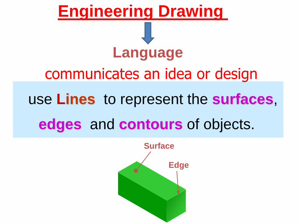
use Lines to represent the surfaces,
edges and contours of objects.
Engineering Drawing
Language
communicates an idea or design
Surface
Edge
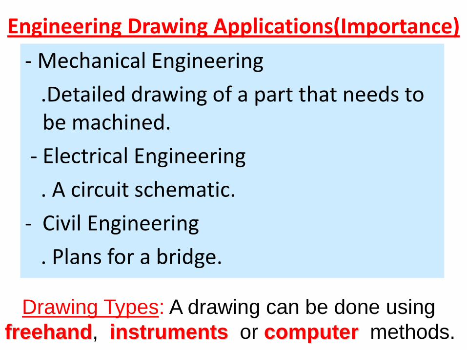
Engineering Drawing Applications(Importance)
- Mechanical Engineering
.Detailed drawing of a part that needs to be machined.
- Electrical Engineering
. A circuit schematic.
- Civil Engineering
. Plans for a bridge.
Drawing Types: A drawing can be done using
freehand, instruments or computer methods.
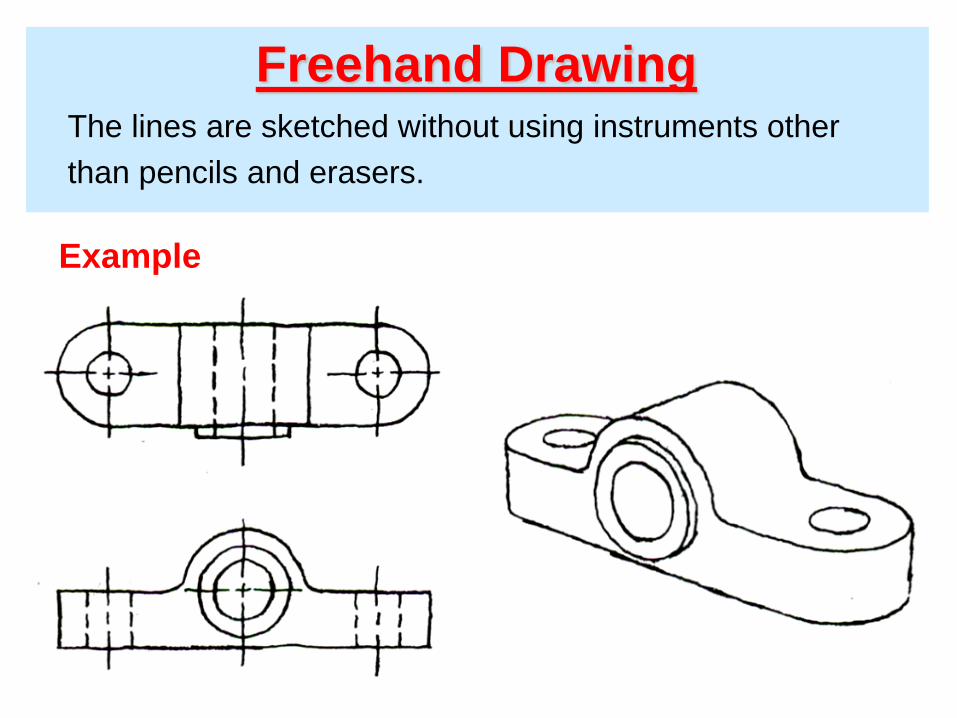
Freehand Drawing The lines are sketched without using instruments other
than pencils and erasers.
Example
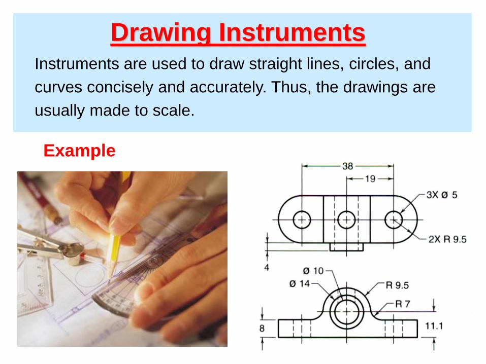
Drawing Instruments Instruments are used to draw straight lines, circles, and
curves concisely and accurately. Thus, the drawings are
usually made to scale.
Example
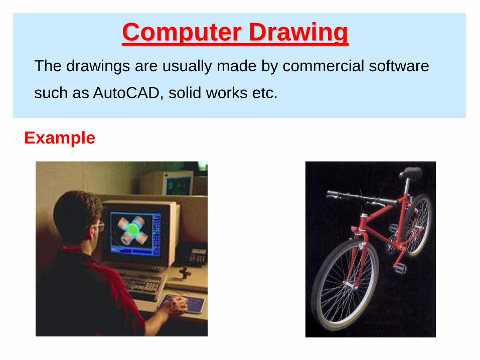
Computer Drawing
The drawings are usually made by commercial software
such as AutoCAD, solid works etc.
Example
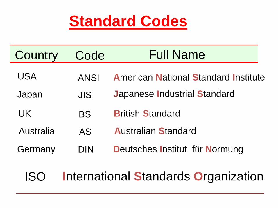
ISO International Standards Organization
Standard Codes
ANSI American National Standard Institute USA
JIS Japanese Industrial Standard Japan
BS British Standard UK
AS Australian Standard Australia
Deutsches Institut für Normung DIN Germany
Country Code Full Name
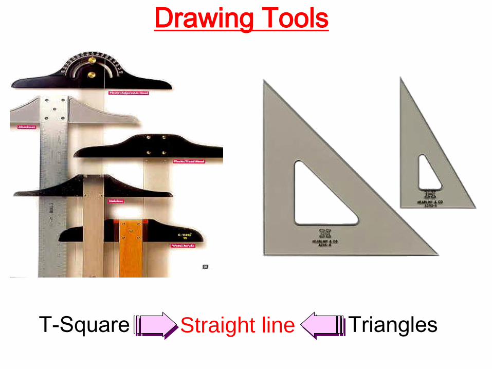
T-Square
Drawing Tools
Triangles Straight line
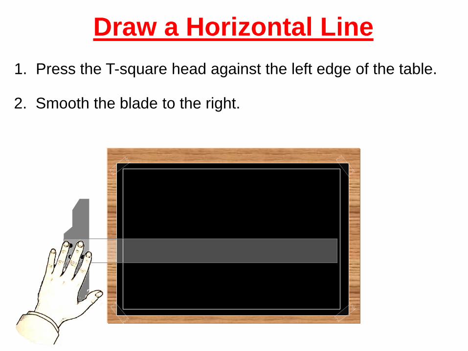
Draw a Horizontal Line
1. Press the T-square head against the left edge of the table.
2. Smooth the blade to the right.
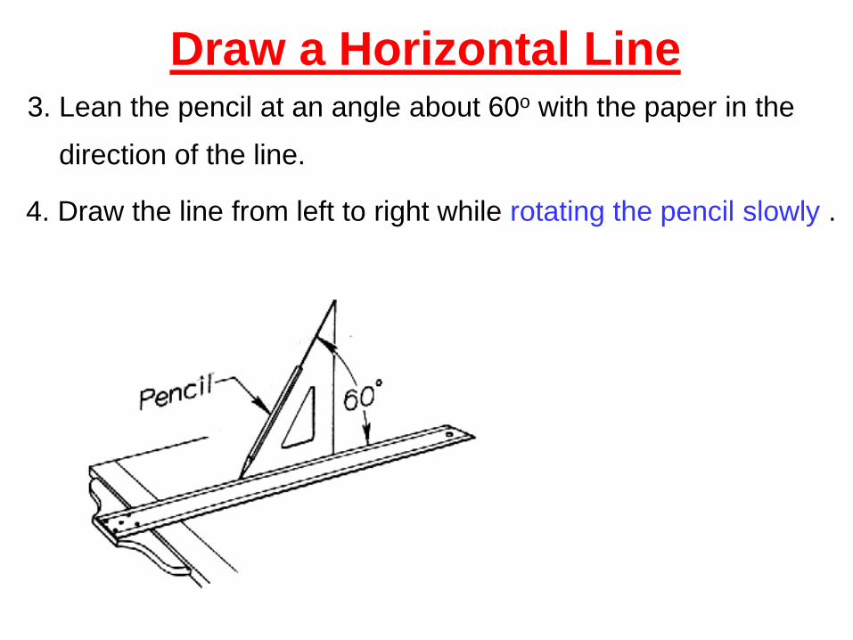
Draw a Horizontal Line 3. Lean the pencil at an angle about 60o with the paper in the
direction of the line.
4. Draw the line from left to right while rotating the pencil slowly .

Draw a Vertical Line 1. Set T-square as before. Place any triangle on T-square edge.
2. Slide your left hand to hold both T-square and triangle in
position.
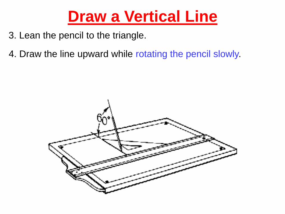
Draw a Vertical Line 3. Lean the pencil to the triangle.
4. Draw the line upward while rotating the pencil slowly.
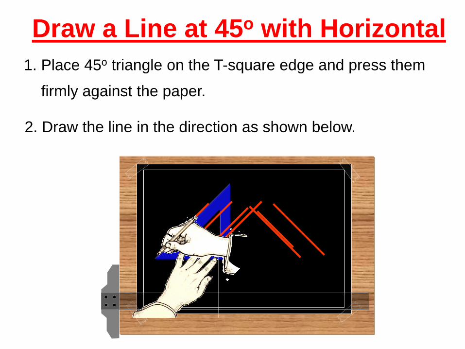
Horizontalwith o45at Line Draw a
2. Draw the line in the direction as shown below.
1. Place 45o triangle on the T-square edge and press them
firmly against the paper.
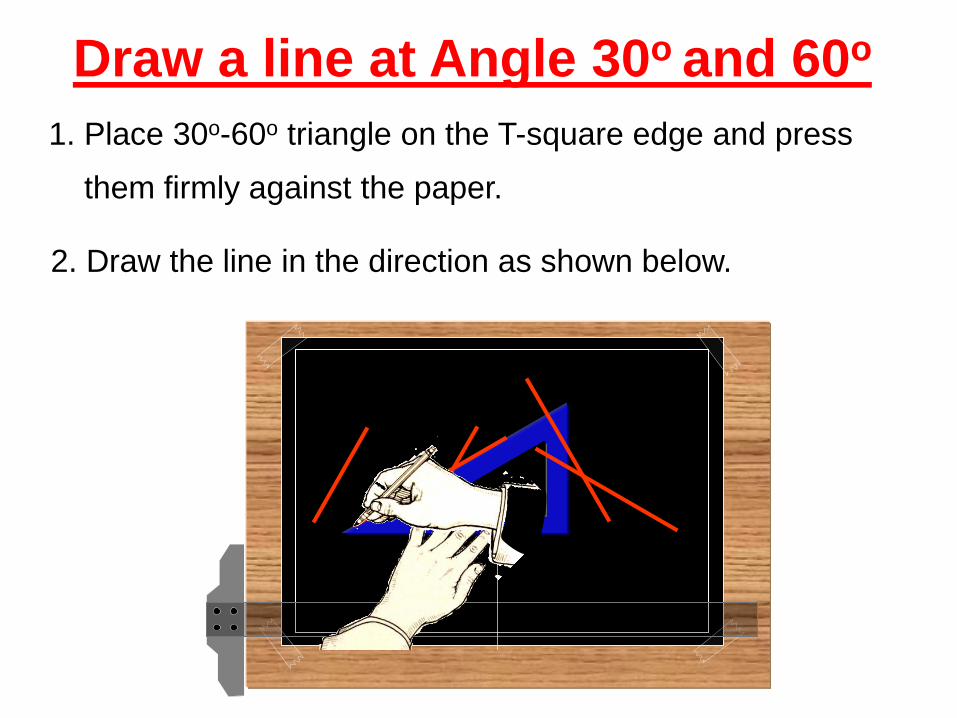
1. Place 30o-60o triangle on the T-square edge and press
them firmly against the paper.
2. Draw the line in the direction as shown below.
o60and o 30Angle Draw a line at
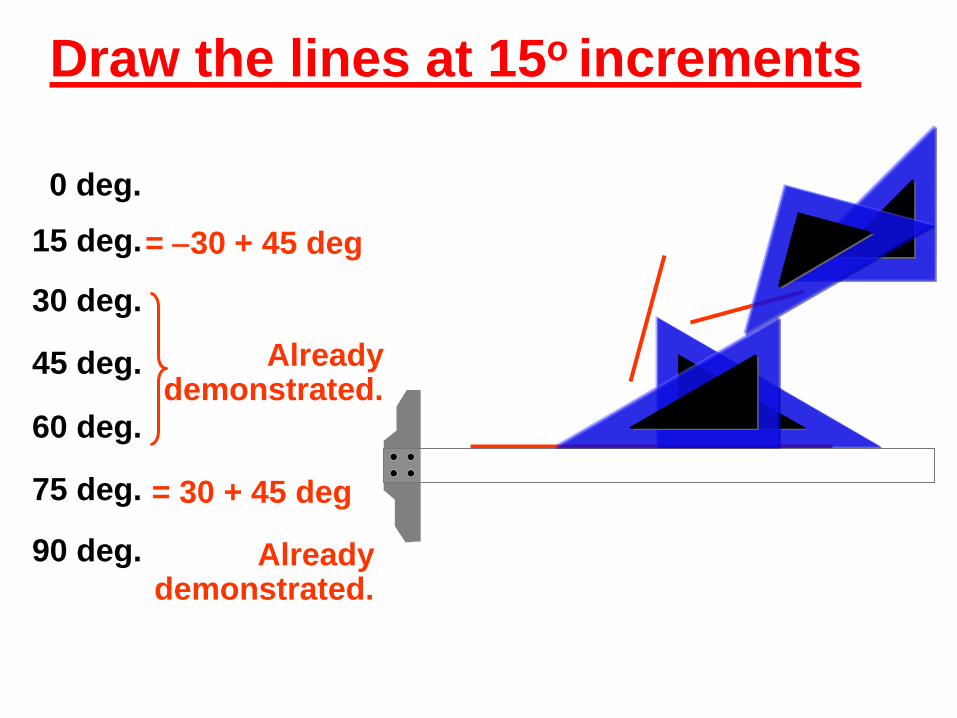
0 deg.
15 deg.
30 deg.
45 deg.
60 deg.
75 deg.
90 deg.
= 30 + 45 deg
Already demonstrated.
= 30 + 45 deg
Already demonstrated.
incrementso 15Draw the lines at
A
B
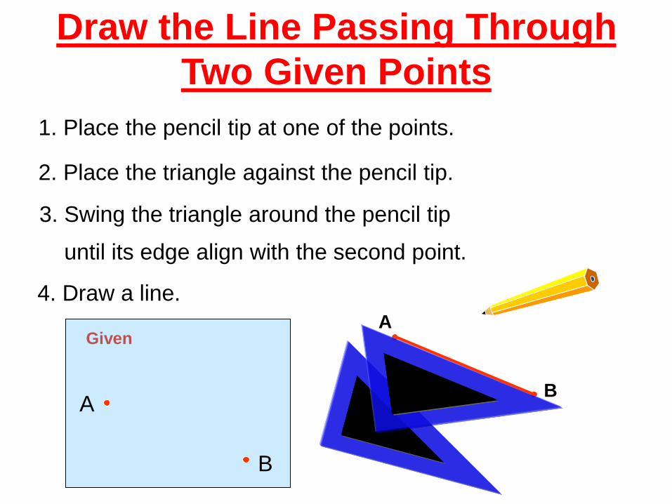
Line Passing ThroughDraw the
Two Given Points
1. Place the pencil tip at one of the points.
2. Place the triangle against the pencil tip.
A
B
Given
3. Swing the triangle around the pencil tip
until its edge align with the second point.
4. Draw a line.
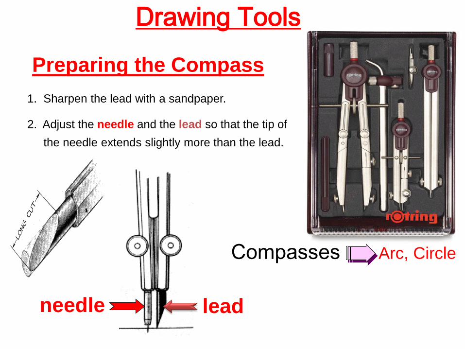
Compasses
Drawing Tools
1. Sharpen the lead with a sandpaper.
2. Adjust the needle and the lead so that the tip of
the needle extends slightly more than the lead.
needle lead
Preparing the Compass
Arc, Circle
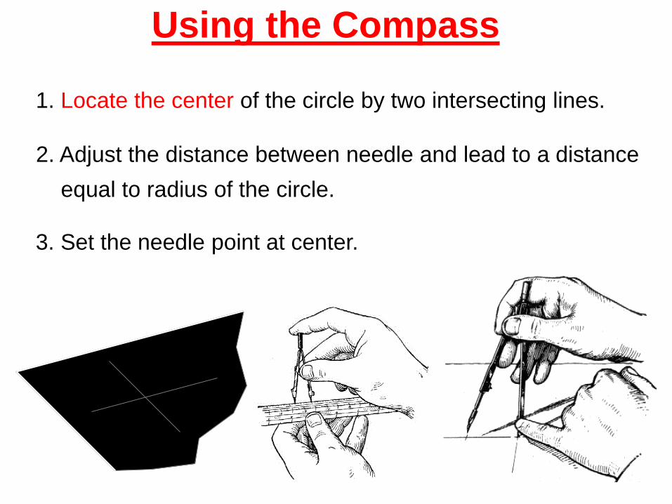
Using the Compass
1. Locate the center of the circle by two intersecting lines.
2. Adjust the distance between needle and lead to a distance
equal to radius of the circle.
3. Set the needle point at center.
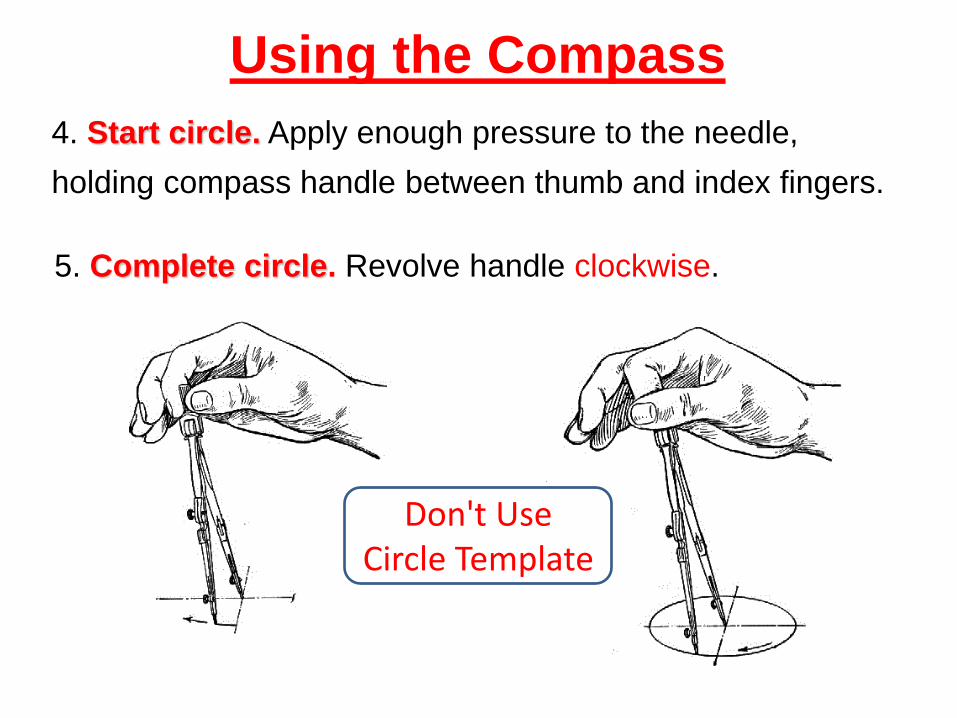
4. Start circle. Apply enough pressure to the needle,
holding compass handle between thumb and index fingers.
5. Complete circle. Revolve handle clockwise.
Using the Compass
Don't Use Circle Template
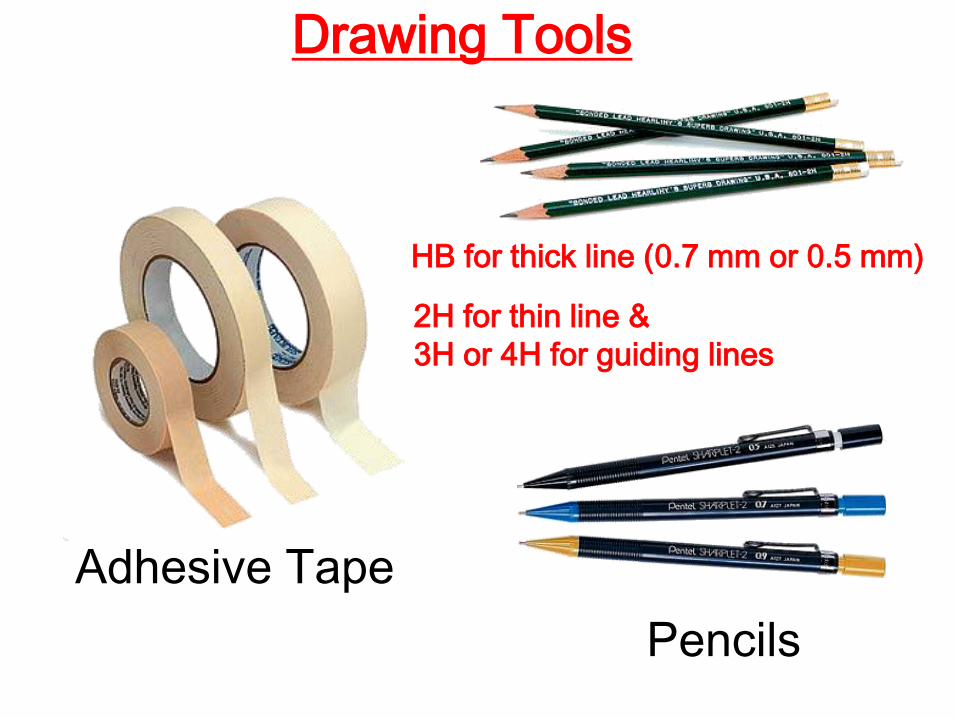
Adhesive Tape
Pencils
HB for thick line (0.7 mm or 0.5 mm)
2H for thin line &
3H or 4H for guiding lines
Drawing Tools
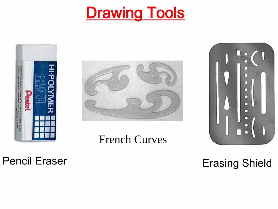
Pencil Eraser Erasing Shield
Drawing Tools
French Curves
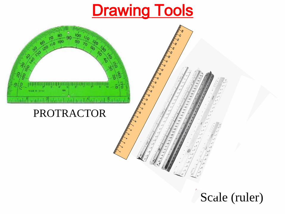
Drawing Tools
PROTRACTOR
Scale (ruler)
Drawing Tools
Note :Don’t use any template of:
- Circles.
- Ellipses.
- Letters.
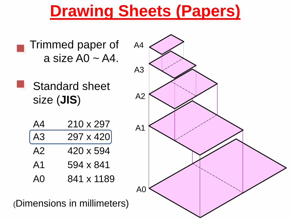
Drawing Sheets (Papers)
Trimmed paper of
a size A0 ~ A4.
Standard sheet
size (JIS)
A4 210 x 297
A3 297 x 420
A2 420 x 594
A1 594 x 841
A0 841 x 1189
A4
A3
A2
A1
A0
(Dimensions in millimeters)
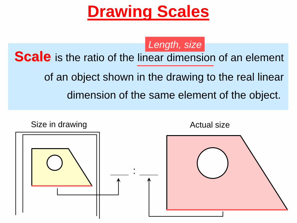
Drawing Scales
Scale is the ratio of the linear dimension of an element
of an object shown in the drawing to the real linear
dimension of the same element of the object.
Size in drawing Actual size
Length, size
:
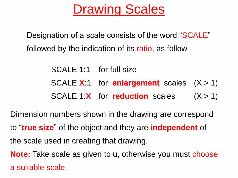
Drawing Scales
Designation of a scale consists of the word “SCALE”
followed by the indication of its ratio, as follow
SCALE 1:1 for full size
SCALE X:1 for enlargement scales (X > 1)
SCALE 1:X for reduction scales (X > 1)
Dimension numbers shown in the drawing are correspond
to “true size” of the object and they are independent of
the scale used in creating that drawing.
Note: Take scale as given to u, otherwise you must choose
a suitable scale.
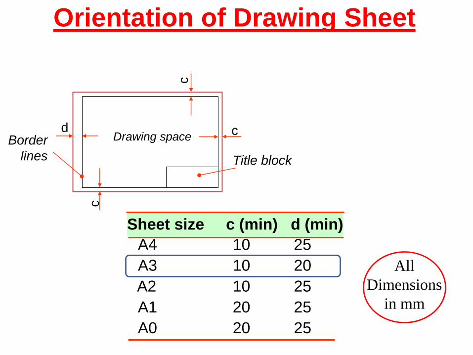
Drawing space
Title block
d
c
c
c Border
lines
Orientation of Drawing Sheet
Sheet size c (min) d (min)
A4 10 25
A3 10 20
A2 10 25
A1 20 25
A0 20 25
All
Dimensions
in mm
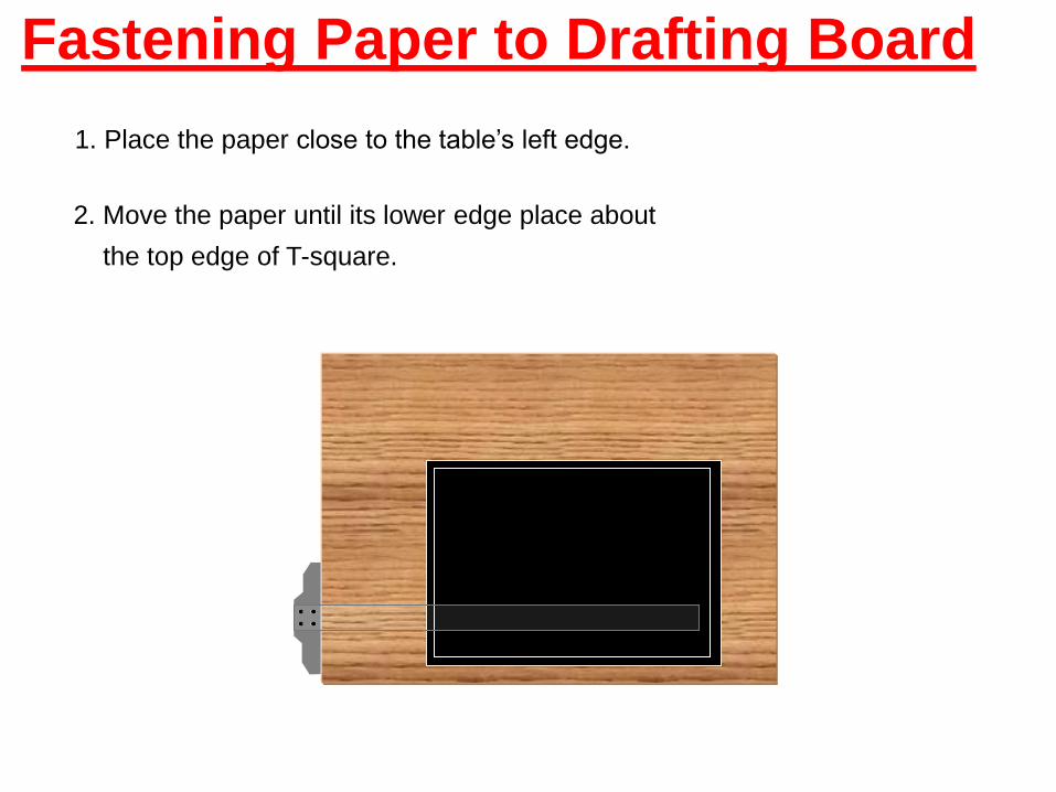
Fastening Paper to Drafting Board
1. Place the paper close to the table’s left edge.
2. Move the paper until its lower edge place about
the top edge of T-square.
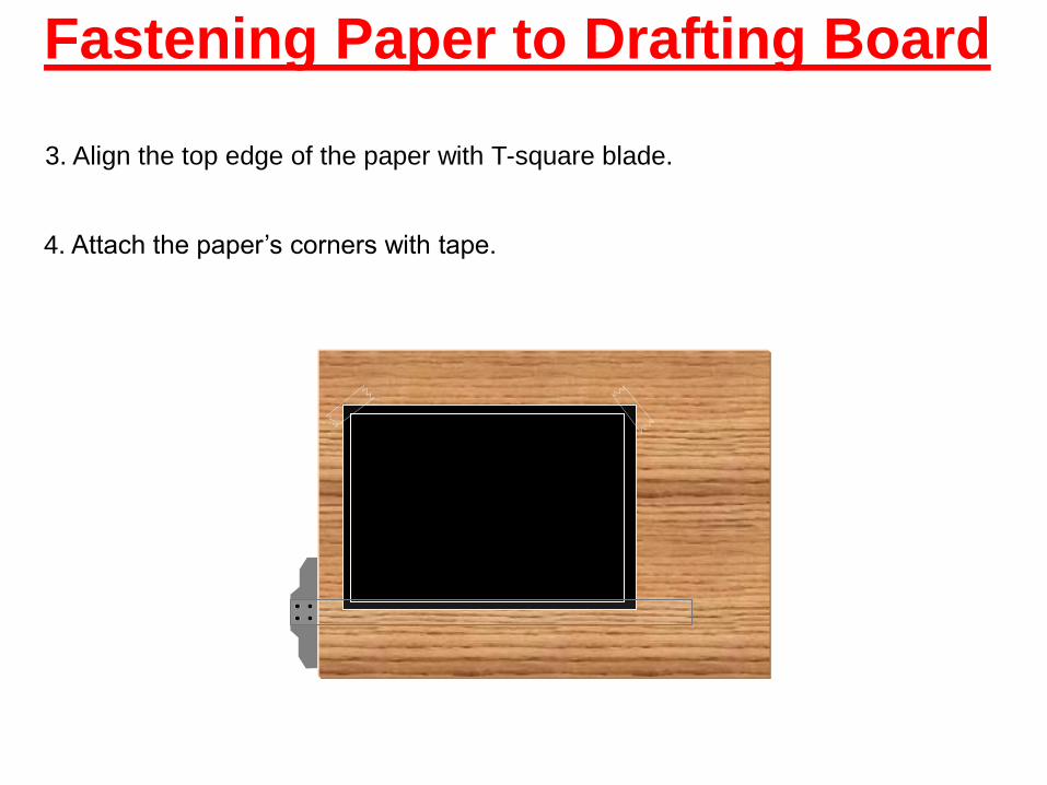
3. Align the top edge of the paper with T-square blade.
4. Attach the paper’s corners with tape.
Fastening Paper to Drafting Board
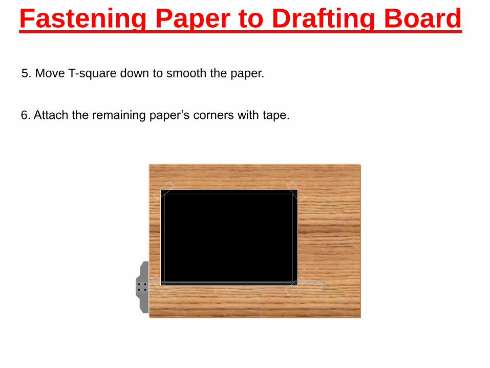
5. Move T-square down to smooth the paper.
6. Attach the remaining paper’s corners with tape.
Fastening Paper to Drafting Board
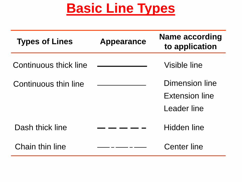
Basic Line Types
Types of Lines Appearance Name according
to application
Continuous thick line Visible line
Continuous thin line Dimension line
Extension line
Leader line
Dash thick line Hidden line
Chain thin line Center line
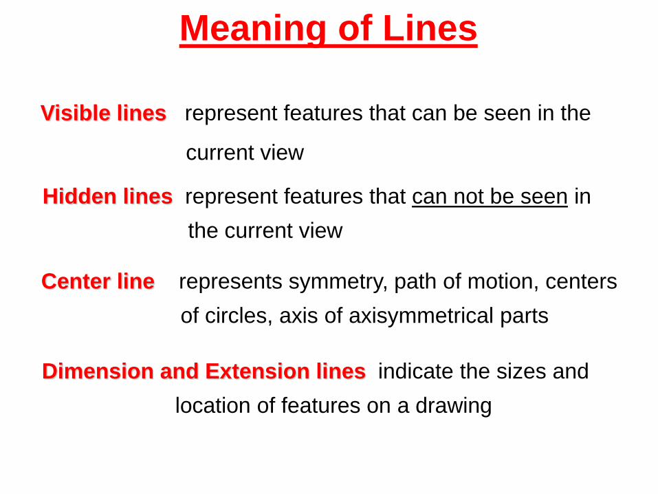
Visible lines represent features that can be seen in the
current view
Meaning of Lines
Hidden lines represent features that can not be seen in
the current view
Center line represents symmetry, path of motion, centers
of circles, axis of axisymmetrical parts
Dimension and Extension lines indicate the sizes and
location of features on a drawing
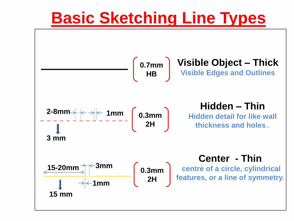
Basic Sketching Line Types
Visible Object – Thick Visible Edges and Outlines
Hidden – Thin Hidden detail for like wall
thickness and holes..
Center - Thin centre of a circle, cylindrical
features, or a line of symmetry.
1mm 2-8mm
3 mm
1mm
3mm 15-20mm
15 mm
0.7mm
HB
0.3mm
2H
0.3mm
2H
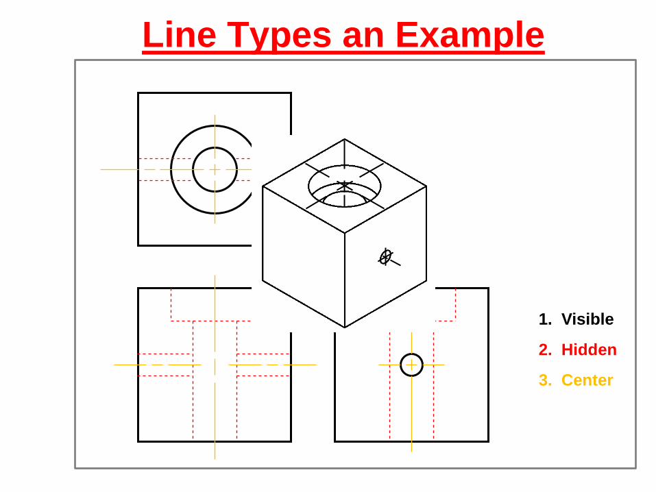
Line Types an Example
1. Visible
2. Hidden
3. Center
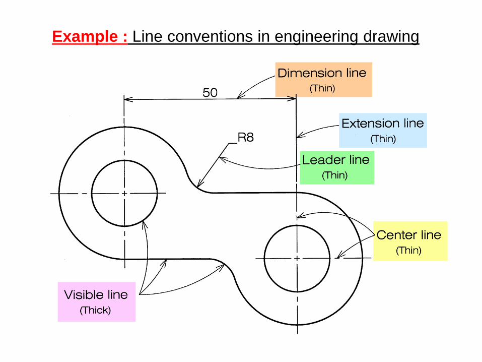
Example : Line conventions in engineering drawing
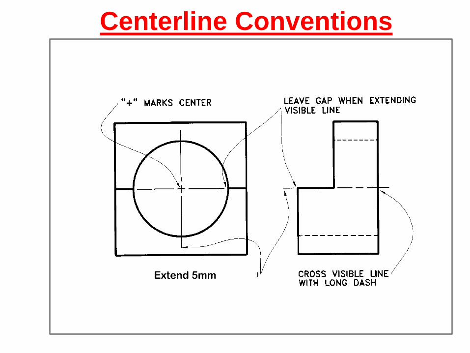
Centerline Conventions
Extend 5mm
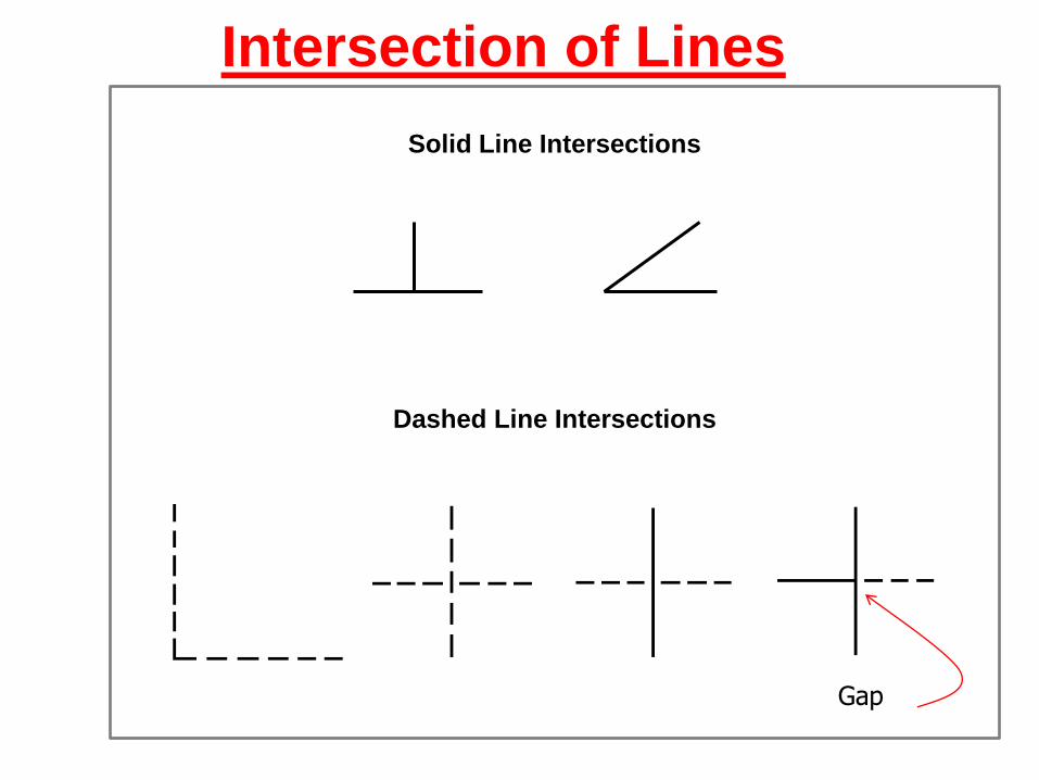
Intersection of Lines
Solid Line Intersections
Dashed Line Intersections
Gap
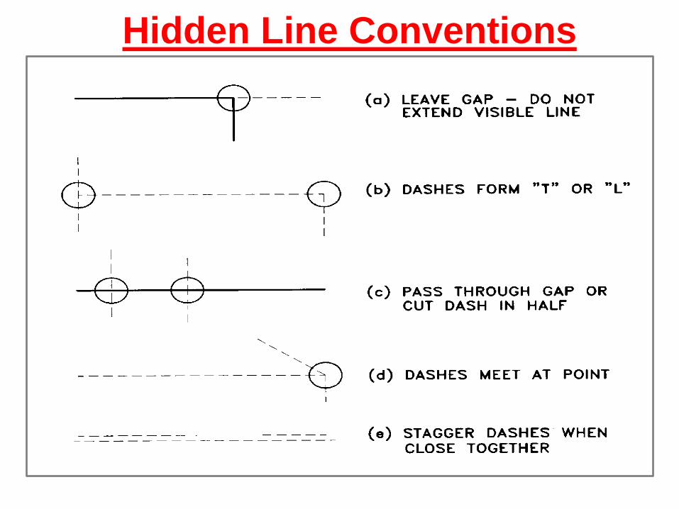
Hidden Line Conventions
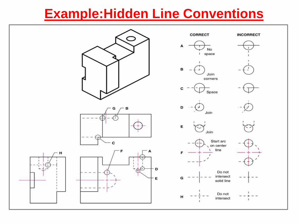
Example:Hidden Line Conventions
ABCDEFGHIJKLMNOPQRSTUVWXYZABCDEFGHIJKLMNOPQRSTU
VWXYZABCDEF
ABCDEFGHIJKLMNOPQRSTUVWXYZABCDEFGHIJKLMNOPQRSTU
VWXYZABCDEF
Lettering
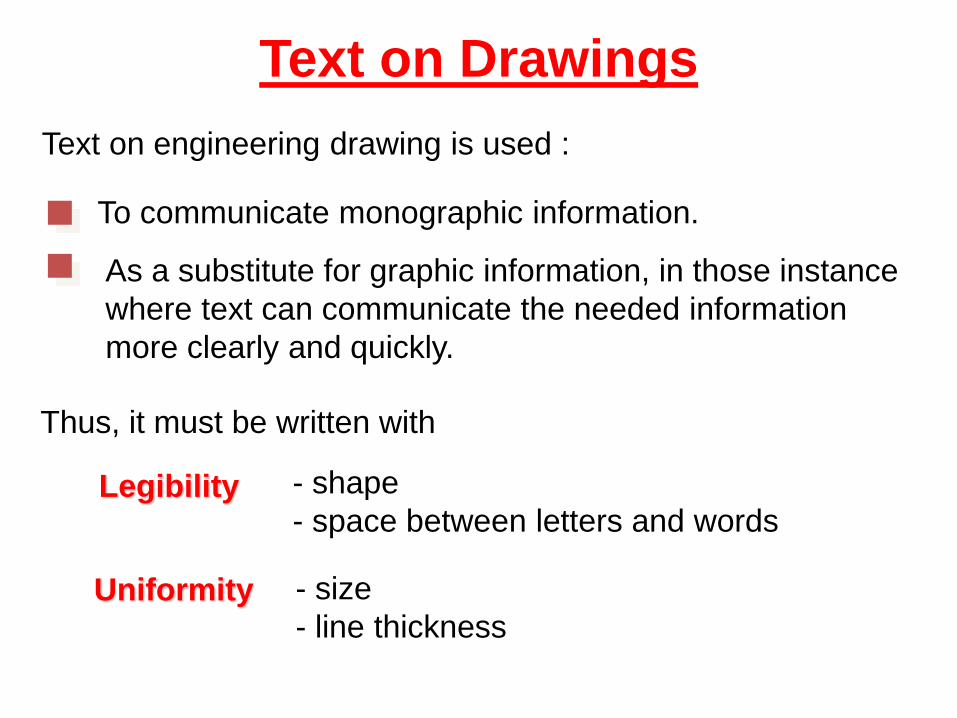
Text on Drawings
Text on engineering drawing is used :
To communicate monographic information.
As a substitute for graphic information, in those instance
where text can communicate the needed information
more clearly and quickly.
Uniformity - size
- line thickness
Legibility - shape
- space between letters and words
Thus, it must be written with
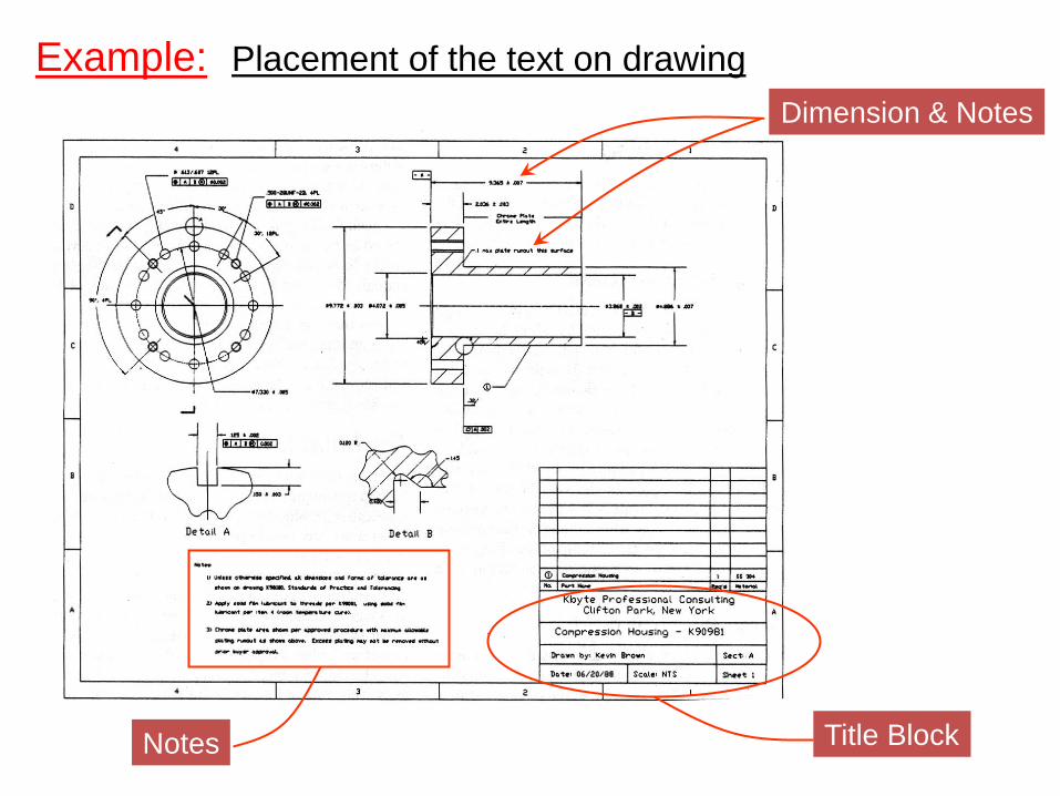
Example: Placement of the text on drawing
Dimension & Notes
Notes Title Block
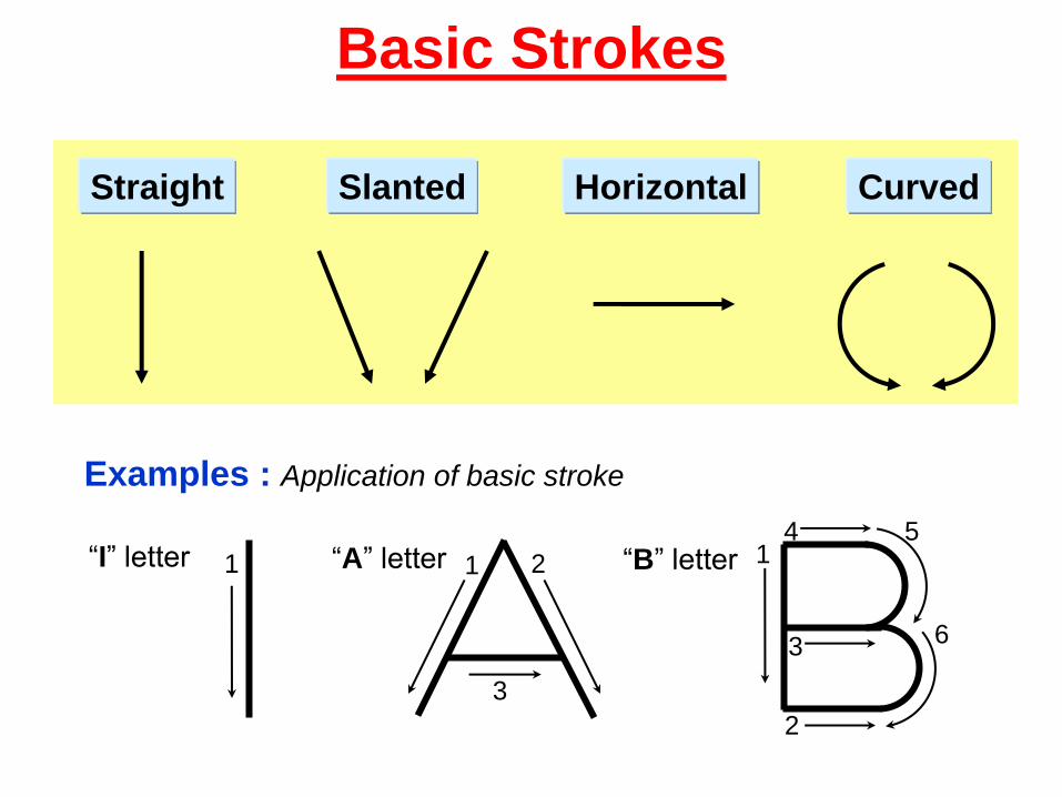
Basic Strokes
Straight Slanted Curved Horizontal
1 1 2
3
Examples : Application of basic stroke
“I” letter “A” letter 1
2
3
4 5
6
“B” letter
Suggested Strokes Sequence
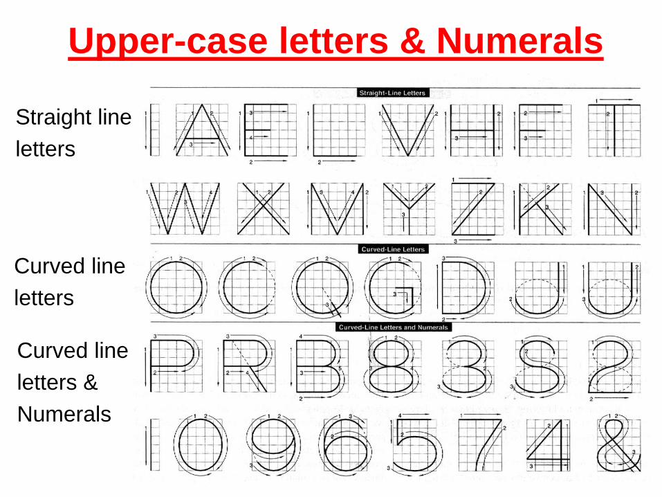
Straight line
letters
Curved line
letters
Curved line
letters &
Numerals
Upper-case letters & Numerals
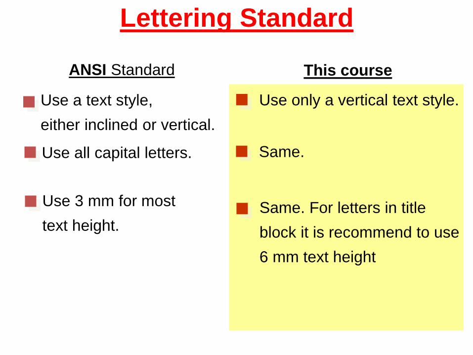
Lettering Standard
ANSI Standard This course
Use a text style,
either inclined or vertical.
Use all capital letters.
Use 3 mm for most
text height.
Use only a vertical text style.
Same.
Same. For letters in title
block it is recommend to use
6 mm text height
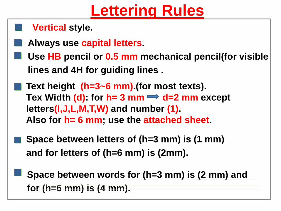
Vertical style.
Always use capital letters.
Use HB pencil or 0.5 mm mechanical pencil(for visible
lines and 4H for guiding lines .
Text height (h=3~6 mm).(for most texts).
Tex Width (d): for h= 3 mm d=2 mm except
letters(I,J,L,M,T,W) and number (1).
Also for h= 6 mm; use the attached sheet.
Space between letters of (h=3 mm) is (1 mm)
and for letters of (h=6 mm) is (2mm).
Lettering Rules
Space between words for (h=3 mm) is (2 mm) and
for (h=6 mm) is (4 mm).
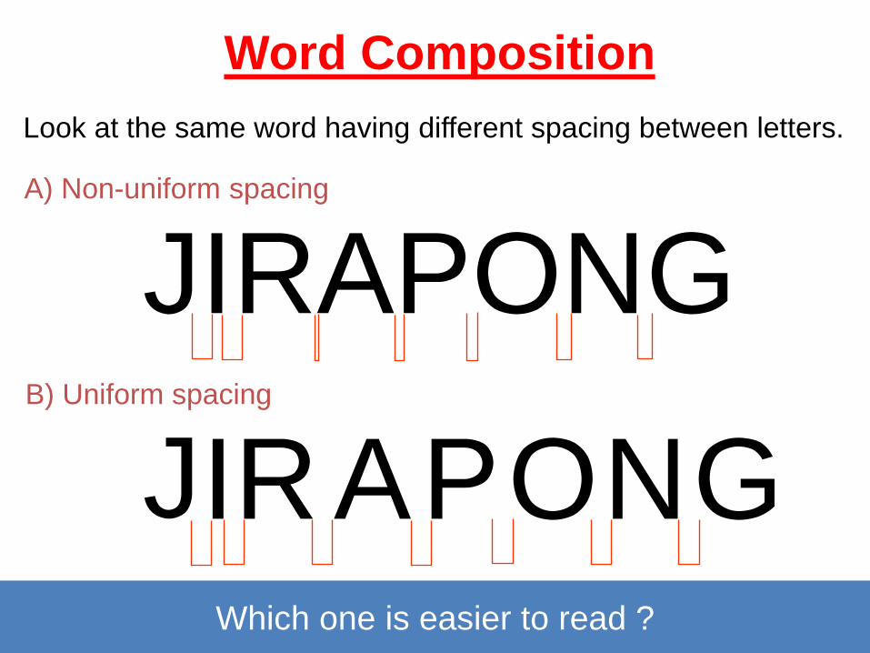
Word Composition
Look at the same word having different spacing between letters.
JIRAPONG
J I G O R N P A
Which one is easier to read ?
A) Non-uniform spacing
B) Uniform spacing
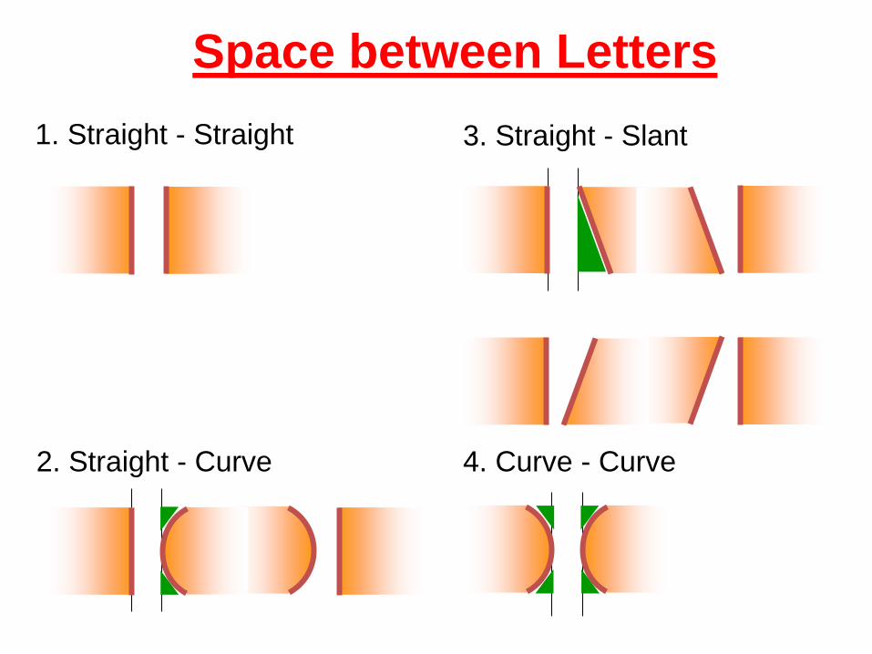
1. Straight - Straight
2. Straight - Curve
3. Straight - Slant
4. Curve - Curve
Space between Letters
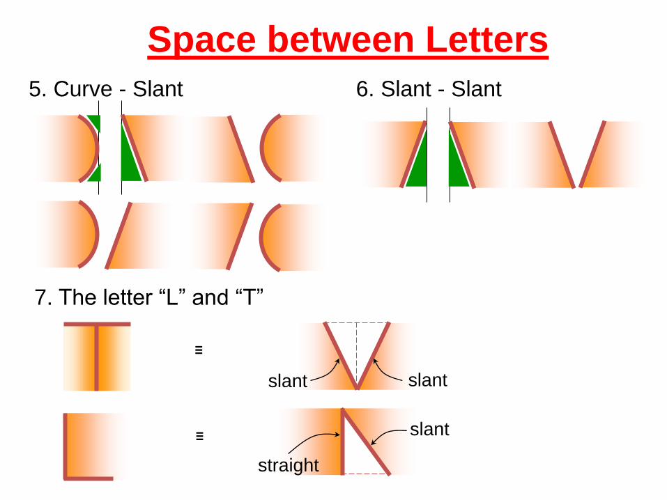
6. Slant - Slant 5. Curve - Slant
7. The letter “L” and “T”
≡
slant slant
≡ slant
straight
Space between Letters
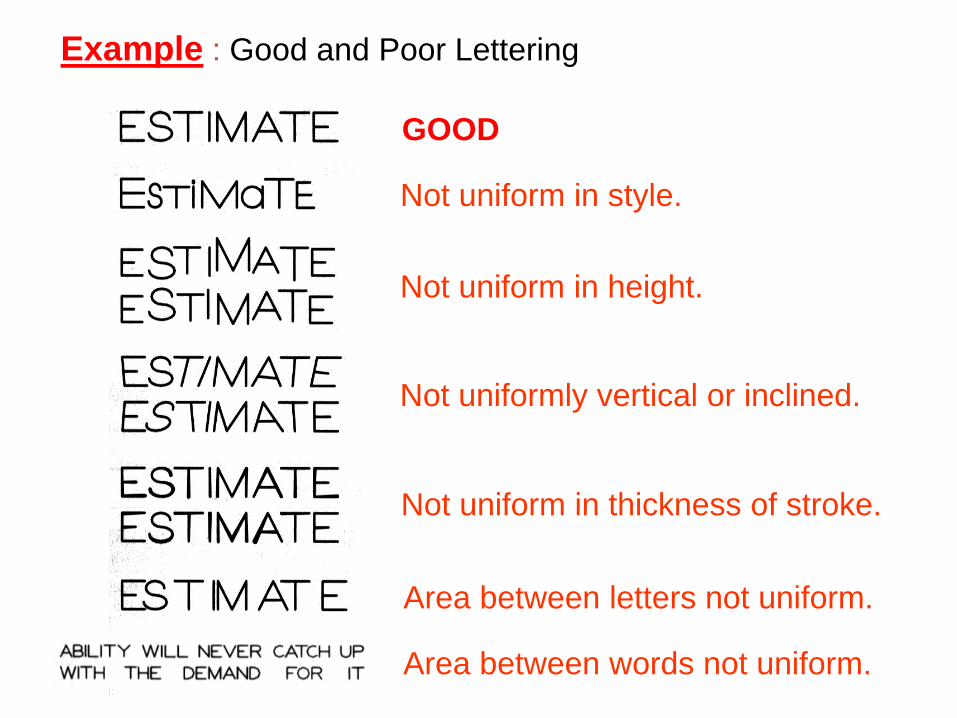
GOOD
Not uniform in style.
Not uniform in height.
Not uniformly vertical or inclined.
Not uniform in thickness of stroke.
Area between letters not uniform.
Area between words not uniform.
Example : Good and Poor Lettering
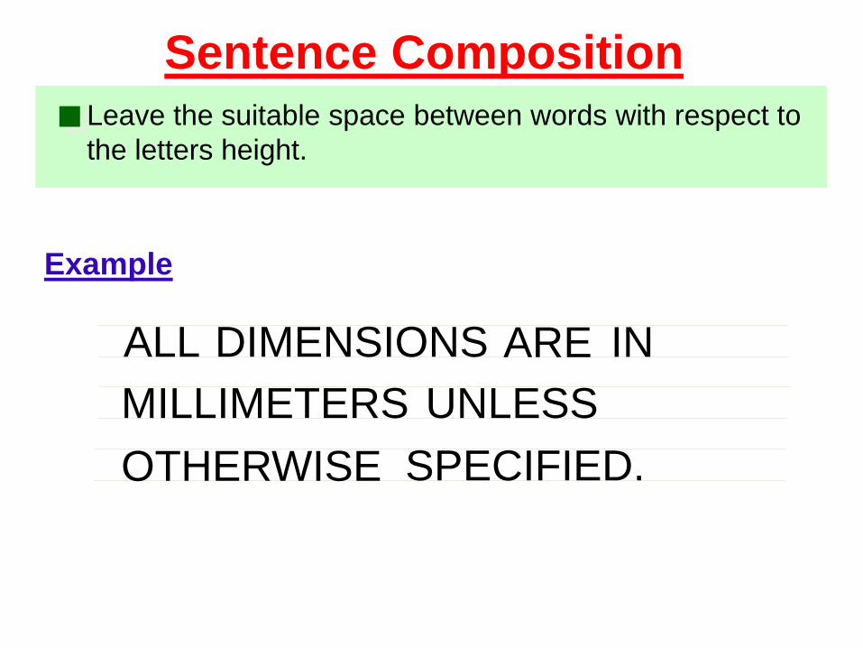
Leave the suitable space between words with respect to
the letters height.
Example
Sentence Composition
ALL DIMENSIONS ARE IN
MILLIMETERS UNLESS
OTHERWISE SPECIFIED.
Title Block Drawing
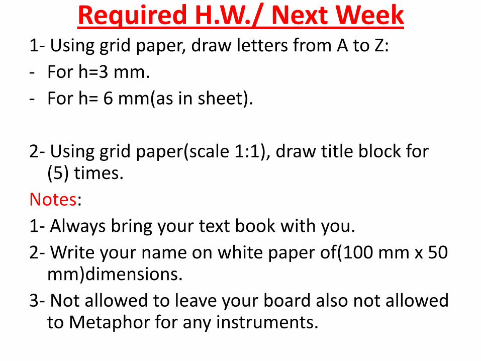
Required H.W./ Next Week 1- Using grid paper, draw letters from A to Z:
- For h=3 mm.
- For h= 6 mm(as in sheet).
2- Using grid paper(scale 1:1), draw title block for (5) times.
Notes:
1- Always bring your text book with you.
2- Write your name on white paper of(100 mm x 50 mm)dimensions.
3- Not allowed to leave your board also not allowed to Metaphor for any instruments.
END